ENGINE PERFORMANCE
2.0L TURBO
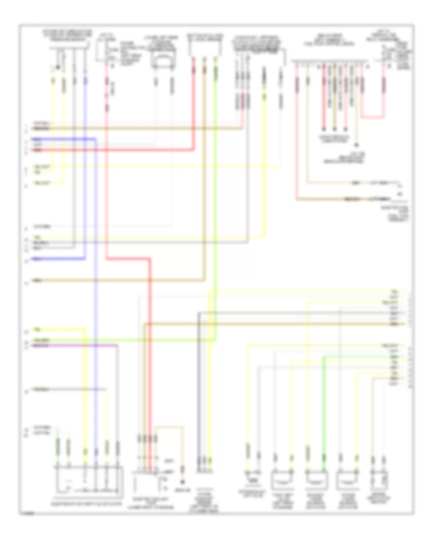
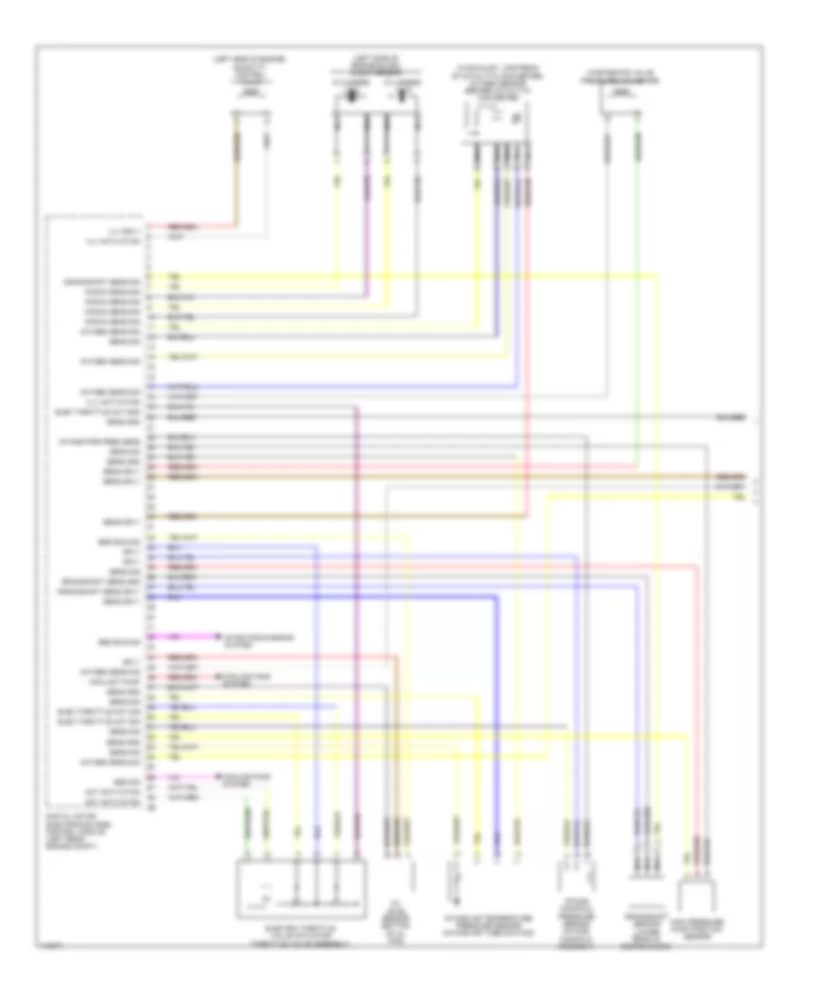
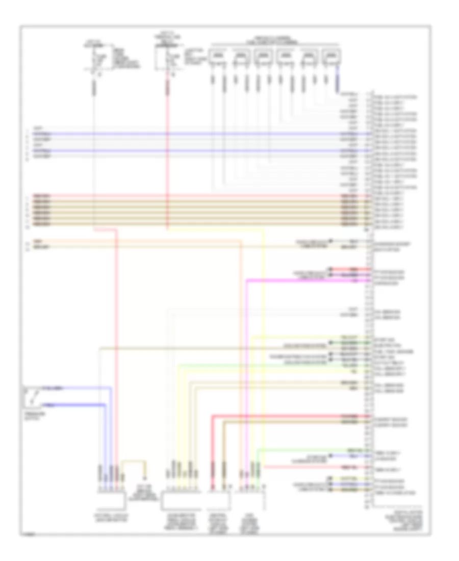
2.0L Turbo, Engine Performance Wiring Diagram (1 of 5) for BMW X3 28i 2013

List of elements for 2.0L Turbo, Engine Performance Wiring Diagram (1 of 5) for BMW X3 28i 2013:
- (intake manifold assembly) intake-manifold pressure sensor
- (left side of engine block, at 1 & 2 cylinder) knock sensor cylinder 1 & 2
- (left side of engine block, at 3 & 4 cylinder) knock sensor cylinder 3 & 4
- (w/o exhaust emission standards euro 6) wastegate valve pressure converter
- Activation elec throttle vlv act
- Activation oil press ctrl valv
- Activation throttle vlv act
- Activation vol ctrl vlv
- Crankshaft sens gnd
- Crankshaft sens sig
- Crankshaft sens sply
- Crankshaft sensor (lower rear of engine block)
- Digital motor electronics (dme) control module (left rear engine compt)
- Elec throttle vlv act gnd
- Elec throttle vlv act sig
- Int air temp pres gnd
- Int air temp pres sens
- Int pipe pres sens gnd
- Int pipe pres sens sply
- Knock sens sig
- Lin bus sig
- Nca
- Oil lvl sens gnd
- Oil lvl sens sig
- Oil lvl sens sply
- Oil press ctrl vlv sply
- Oxy sens aft cat conv sply
- Oxygen sens aft cat conv gnd
- Oxygen sens bef cat conv gnd
- Oxygen sens bef cat conv sply
- Oxygen sens sig
- Oxygen sensor after catalytic converter (in exhaust, downstream of catalytic converter)
- Press sens gnd
- Press sens sig
- Press sens sply
- Quantity control valve (left side of engine)
- Rail press sens gnd
- Rail press sens sply
- Rail pressure sensor (engine fuel rail)
- Red
- Starting/charging system
- Temp sens sig
- Venture nozzle pressure sensor
- Vol ctrl vlv sply
- Wastegate vlv activation press conv
- Wastegate vlv press conv sply
- Zero-gear sensor (top of transmission)
- Zero-gear snsr gnd
- Zero-gear snsr sig
- Zero-gear snsr sply
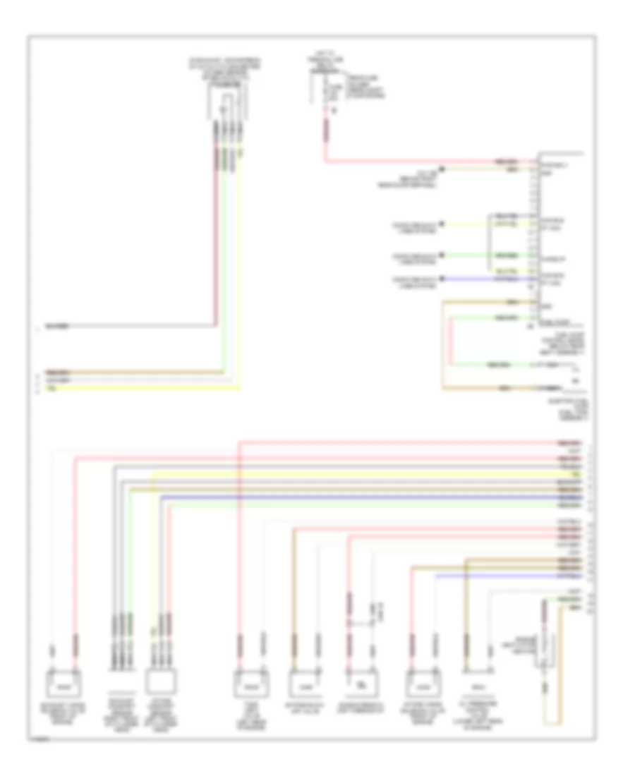
2.0L Turbo, Engine Performance Wiring Diagram (2 of 5) for BMW X3 28i 2013
List of elements for 2.0L Turbo, Engine Performance Wiring Diagram (2 of 5) for BMW X3 28i 2013:
- (below rear seat assembly) fuel pump control (ekps)
- (bottom of oil pan) oil level sensor
- (in exhaust, upstream of catalytic converter) oxygen sensor before catalytic converter
- (intake air tube ducting) intake air temperature pressure sensor
- (lower left rear of engine) oil pressure control valve
- (pins 10 to 12 not used)
- (pins 14 & 15 not used)
- (pins 3 to 8 not used)
- 200w
- 400w
- Bypass blow- off valve
- Computer data lines system
- Electric coolant pump (lower front of engine)
- Electric fuel pump (fuel tank assembly)
- Electromotive throttle actuator
- Engine ventilation heating
- Exhaust vanos solenoid actuator
- Fuse 20a
- Fuse 50a
- Hot at all times
- Hot w/ terminal 30b relay energized
- Intake camshaft sensor (left front of cylinder head)
- Intake vanos solenoid actuator
- Nca
- Power distribution box (left rear of engine compt)
- Rear fuse holder (rear compt floor board)
- Red
- Tank vent valve (left rear of engine)
- X664 2b
- Z10 12b (behind right rear quarterpanel)
- Z6000 3b
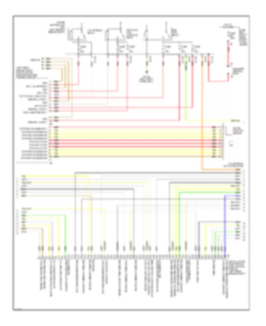
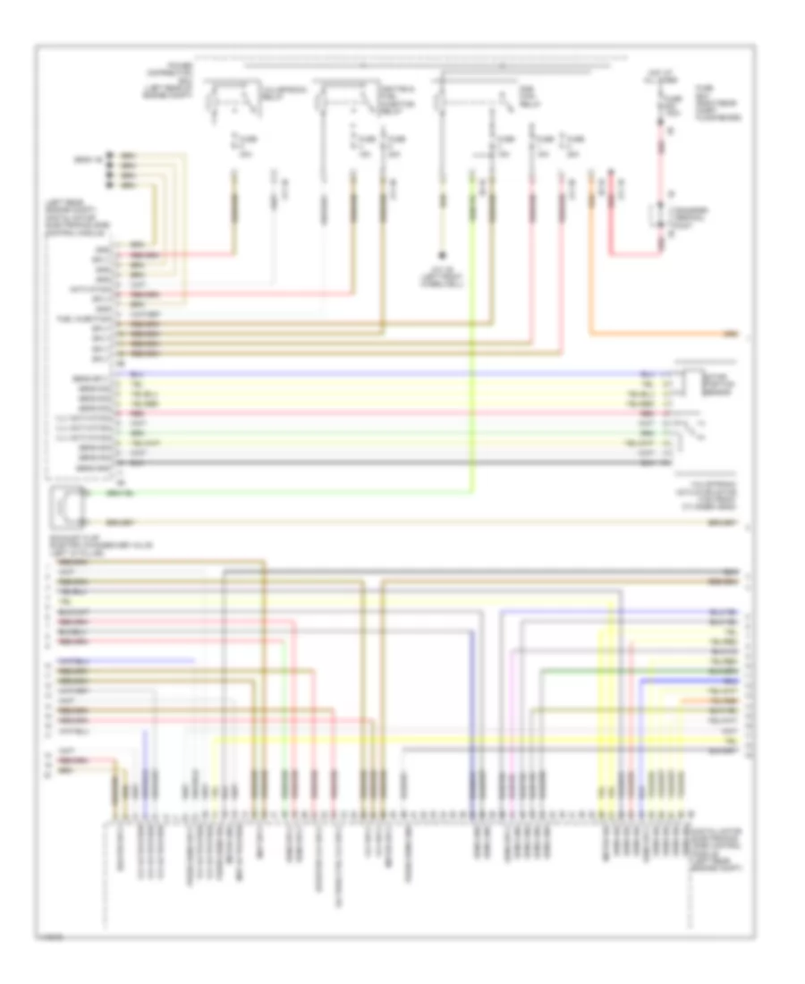
2.0L Turbo, Engine Performance Wiring Diagram (3 of 5) for BMW X3 28i 2013
List of elements for 2.0L Turbo, Engine Performance Wiring Diagram (3 of 5) for BMW X3 28i 2013:
- (left rear engine compt) digital motor electronics (dme) control module
- Activation
- Activation blow-off vlv
- Activation characteristic map hermostat
- Activation elect coolant pump
- Activation tank vent vlv
- Activation vlvelct rly
- Blow-off valve sply
- Characteristic map
- Digital motor electronics (dme) control module (left rear engine compt)
- Dme main relay
- Engine coolant temp sens gnd
- Engine oil press/temp sens gnd
- Engine oil press/temp sens sig
- Engine oil press/temp sens sply
- Engine vent heating gnd
- Engine vent heating sply
- Exhaust activation vanos solenoid vlv
- Exhaust camshaft sens gnd
- Exhaust camshaft sens sig
- Exhaust camshaft sens sply
- Exhaust vanos sol valv sply
- Fuel injectors sply
- Fuse 100a
- Fuse 15a
- Fuse 20a
- Fuse 40a
- Fuse box (right rear compt floor board)
- Gnd
- Hot at all times
- Hot-film air mass meter gnd
- Hot-film air mass meter sig
- Hot-film air mass meter sply
- Ignition & fuel injection relay
- Inlet activation vanos sol vlv
- Intake camshaft sens gnd
- Intake camshaft sens sig
- Intake camshaft sens sply
- Intake vanos sol vlv sply
- Lin bus sig
- Motor position sensor
- Mtr activation
- Mtr position snse gnd
- Mtr position snse sig
- Mtr position snse sply
- Power distribution box (left rear of engine compt)
- Red
- Sply ign
- Sply valvetronic
- Tank vent vlv sply
- Temp sens sig
- Terminal 15 sply
- Thermostat supy
- Transfer terminal point
- Valvetronic actuator motor
- Valvetronic relay
- Z10 1b (left front wheelwell)
- Z11 1b
- Z11 3b
- Z11 4b
- Z6000 4b
- Z8 1b
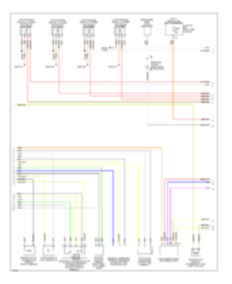
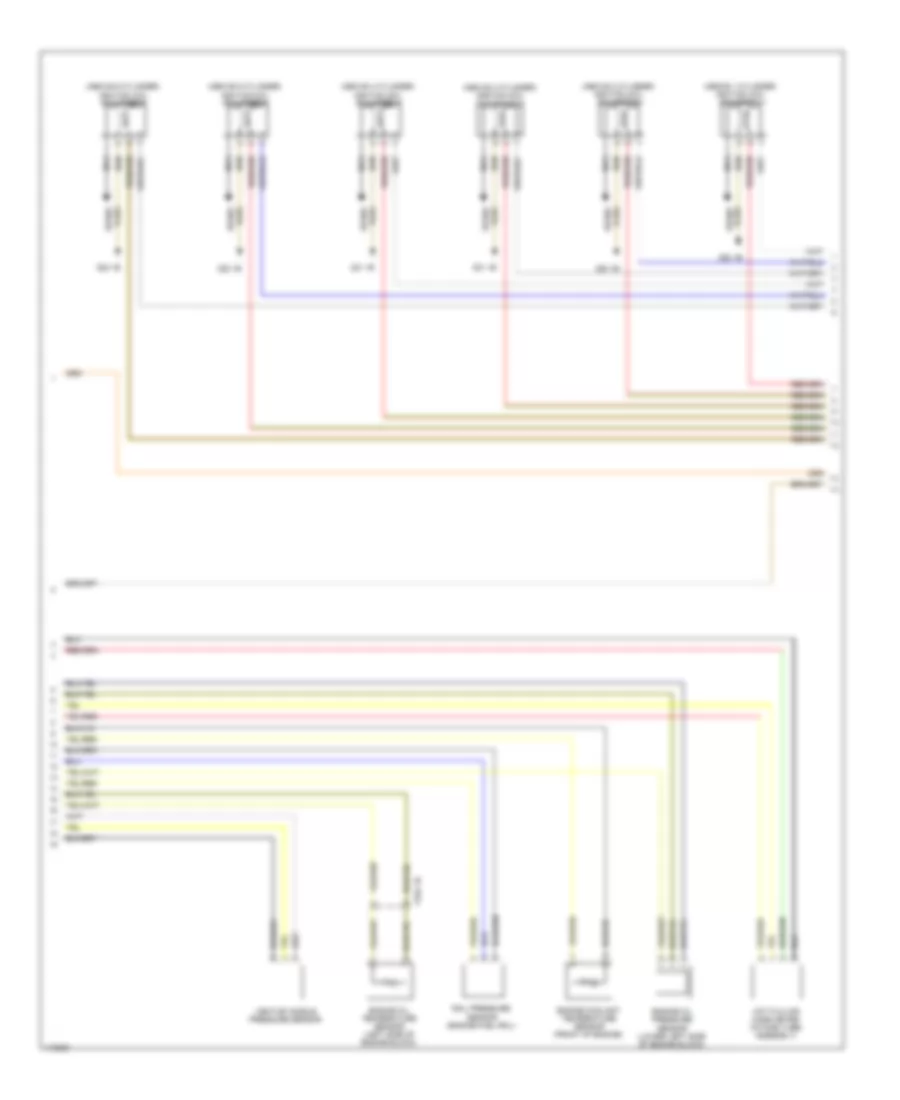
2.0L Turbo, Engine Performance Wiring Diagram (4 of 5) for BMW X3 28i 2013
List of elements for 2.0L Turbo, Engine Performance Wiring Diagram (4 of 5) for BMW X3 28i 2013:
- (rear cargo area) dc/dc converter
- (top of engine, above 1 cylinder) ignition coil cylinder 1
- (top of engine, above 2 cylinder) ignition coil cylinder 2
- (top of engine, above 3 cylinder) ignition coil cylinder 3
- (top of engine, above 4 cylinder) ignition coil cylinder 4
- 12b
- Car access system (left side of dash)
- Characteristic map thermostat
- Electrical wastegate valve (w/ exhaust emissions standard euro 6) (exhaust manifold assembly)
- Engine coolant temperature sensor (front of engine)
- Engine oil pressure/ temperature sensor (lower left side of engine block)
- Exhaust camshaft sensor (right front of cylinder head)
- Exhaust flap electric changeover valve (left "d" pillar)
- Fuse 15a
- Hot film air mass meter (intake tube assembly)
- Hot w/ terminal 30b relay energized
- Junction box (right side of dash)
- Nca
- Plug spark
- Rear fuse holder (rear compt floor board) 12b
- Rotor position sensor
- Spark plug
- Z6000 1b
- Z6000 2b
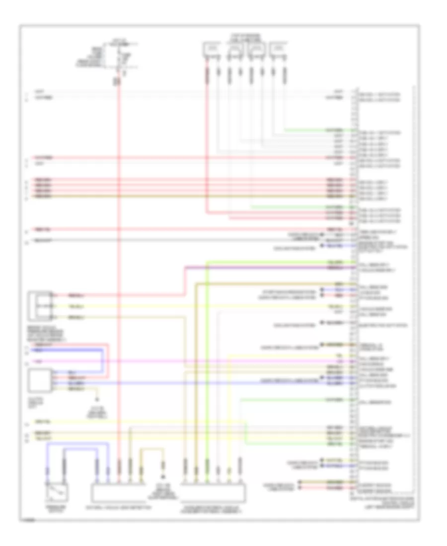
2.0L Turbo, Engine Performance Wiring Diagram (5 of 5) for BMW X3 28i 2013
List of elements for 2.0L Turbo, Engine Performance Wiring Diagram (5 of 5) for BMW X3 28i 2013:
- (top of engine) fuel injectors
- 11b
- Accelerator pedal module (accelerator pedal assembly)
- Brake vacuum pressure sensor (on vacuum brake booster assembly)
- Cas sub-bus
- Clutch module (m/t)
- Clutch module sig
- Computer data lines system
- Cooling fans system
- Digital motor electronics (dme) control module (left rear engine compt)
- Electric fan activation
- Engine start sig
- Engine start sig electric fan activation cut-out rly
- Flexray bus sig
- Fuel inj 1 activation
- Fuel inj 1 sply
- Fuel inj 2 activation
- Fuel inj 2 sply
- Fuel inj 3 activation
- Fuel inj 3 sply
- Fuel inj 4 activation
- Fuel inj 4 sply
- Fuse 5a
- Hall sens gnd
- Hall sens sig
- Hall sens sply
- Hall sensor sig
- Hot at all times
- Ign coil 1 activation
- Ign coil 1 sply
- Ign coil 2 activation
- Ign coil 2 sply
- Ign coil 3 activation
- Ign coil 3 sply
- Ign coil 4 activation
- Ign coil 4 sply
- Lin bus sig
- Natural vacuum leak detection
- Natural vacuum leak detection electric changeover vlv
- Pnk/red
- Pressure switch
- Pt-can bus sig
- Rear fuse holder (rear compt floor board)
- Red
- Speed sig
- Starting/charging system
- Term 30b pwr sply
- Terminal 15 sply
- Terminal 15 wake-up sig
- Vacuum snsr gnd
- Vacuum snsr sig
- Vacuum snsr sply
- Z10 14b (behind right rear quarterpanel)
- Z10 7b (driver's footwell)
3.0L TURBO
3.0L Turbo, Engine Performance Wiring Diagram (1 of 5) for BMW X3 28i 2013
List of elements for 3.0L Turbo, Engine Performance Wiring Diagram (1 of 5) for BMW X3 28i 2013:
- (in exhaust, upstream of catalytic converter) oxygen sensor before catalytic converter
- (left side of engine block) knock sensor
- (left side of engine) quantity control valve
- Act activation
- Bsd bus sig
- Bsd sig
- Coolant pump
- Cooling fans system
- Crankshaft sens gnd
- Crankshaft sens sig
- Crankshaft sens sply
- Crankshaft sensor (lower rear of engine block)
- Cylinders 1 & 3
- Cylinders 4 & 6
- Digital motor electronics (dme) control module (left rear engine compt)
- Elec throttle act gnd
- Elec throttle act sig
- Electric throttle valve actuator (throttle valve assembly)
- High pressure pump position sensor
- Intake air temperature pressure sensor (intake air tube ducting)
- Intake manifold pressure sensor (intake manifold assembly)
- Intake pipe pres sens
- Knock sens sig
- Nca
- Oil level sensor (bottom of oil pan)
- Oxygen sens sig
- Sens gnd
- Sens sig
- Sens sply
- Sply
- Starting/charging system
- Vlv activation
- Vlv sply
- Wastegate valve pressure converter
3.0L Turbo, Engine Performance Wiring Diagram (2 of 5) for BMW X3 28i 2013
List of elements for 3.0L Turbo, Engine Performance Wiring Diagram (2 of 5) for BMW X3 28i 2013:
- (in exhaust, downstream of catalytic converter) oxygen sensor after catalytic converter
- Bypass blow- off valve
- Can bus
- Characteristic map thermostat
- Computer data lines system
- Electric fuel pump (fuel tank assembly)
- Engine ventilation heating
- Exhaust camshaft sensor (right front of cylinder head)
- Exhaust vanos solenoid valve (front of engine)
- Fuel pump
- Fuel pump control (ekps) (below rear seat assembly)
- Fuse 20a
- Gnd
- Hot w/ terminal 30b relay energized
- Intake camshaft sensor (left front of cylinder head)
- Intake vanos solenoid valve (front of engine)
- Nca
- Oil pressure control valve (lower left rear of engine)
- Pt can
- Pwr sply
- Rear fuse holder (rear compt floor board)
- Tank vent valve (left rear of engine)
- Wake-up
- X705 1b
- Z10 12b (behind right rear quarterpanel)
3.0L Turbo, Engine Performance Wiring Diagram (3 of 5) for BMW X3 28i 2013
List of elements for 3.0L Turbo, Engine Performance Wiring Diagram (3 of 5) for BMW X3 28i 2013:
- (left rear engine compt) digital motor electronics (dme) control module
- Activation
- Digital motor electronics (dme) control module (left rear engine compt)
- Diverter vlv sply
- Dme main relay
- Exhaust flap electric changeover valve (left "d" pillar)
- Fuel injection
- Fuse 100a
- Fuse 15a
- Fuse 20a
- Fuse 40a
- Fuse box (right rear compt floor board)
- Gnd
- Heater sply
- Hot at all times
- Ignition & fuel injection relay
- Map activation
- Map sply
- Meter gnd
- Meter sig
- Meter sply
- Motor position sensor
- Oil pres ctrl vlv sply
- Power distribution box (left rear of engine compt)
- Press sens gnd
- Press sens sig
- Press sens sply
- Red
- Sens gnd
- Sens sig
- Sens sply
- Sply
- Transfer terminal point
- Valvetronic actuator motor (top front cylinder head)
- Valvetronic relay
- Vlv activation
- Vlv sply
- Z10 1b (left front wheelwell)
- Z11 1b
- Z11 3b
- Z11 4b
- Z6000 1b
- Z8 1b
3.0L Turbo, Engine Performance Wiring Diagram (4 of 5) for BMW X3 28i 2013
List of elements for 3.0L Turbo, Engine Performance Wiring Diagram (4 of 5) for BMW X3 28i 2013:
- (above 1 cylinder) ignition coil cylinder 1
- (above 2 cylinder) ignition coil cylinder 2
- (above 3 cylinder) ignition coil cylinder 3
- (above 4 cylinder) ignition coil cylinder 4
- (above 5 cylinder) ignition coil cylinder 5
- (above 6 cylinder) ignition coil cylinder 6
- Engine coolant temperature sensor (front of engine)
- Engine oil pressure sensor (lower left side of engine block)
- Engine oil temperature sensor (left side of engine block)
- Hot film air mass meter (intake tube assembly)
- Nca
- Plug spark
- Rail pressure sensor (engine fuel rail)
- Spark plug
- Venturi nozzle pressure sensor
- X704 1b
- Z20 1b
- Z21 1b
- Z22 1b
3.0L Turbo, Engine Performance Wiring Diagram (5 of 5) for BMW X3 28i 2013
List of elements for 3.0L Turbo, Engine Performance Wiring Diagram (5 of 5) for BMW X3 28i 2013:
- (above cylinders) fuel injector cylinders
- Accelerator pedal module (accelerator pedal assembly)
- Car access system (left side of dash)
- Car bus sig
- Central gateway module (left side of dash)
- Computer data lines system
- Cooling fans system
- Cut-out relay
- Diagnosis socket
- Digital motor electronics (dme) control module (left rear engine compt)
- Electric fan
- Exh flap sig
- Flexray bus sig
- Fuel inj 1 activation
- Fuel inj 1 sply
- Fuel inj 2 activation
- Fuel inj 2 sply
- Fuel inj 3 activation
- Fuel inj 3 sply
- Fuel inj 4 activation
- Fuel inj 4 sply
- Fuel inj 5 activation
- Fuel inj 5 sply
- Fuel inj 6 activation
- Fuel inj 6 sply
- Fuel tank leakage
- Fuse 15a
- Fuse 5a
- Hal sens sig
- Hall sens gnd
- Hall sens sply
- Hot at all times
- Hot w/ terminal 30b relay energized
- Ign coil 1 activation
- Ign coil 1 sply
- Ign coil 2 activation
- Ign coil 2 sply
- Ign coil 3 activation
- Ign coil 3 sply
- Ign coil 4 activation
- Ign coil 4 sply
- Ign coil 5 activation
- Ign coil 5 sply
- Ign coil 6 activation
- Ign coil 6 sply
- Junction box (right side of dash)
- Lin bus sig
- Natural vacuum leak detection
- Pnk/red
- Power distribution system
- Pressure switch
- Pt-can bus sig
- Rear fuse holder (rear compt floor board)
- Red
- Start sig
- Starting/ charging system
- Term 15 sply
- Term 15 wake up sig
- Term 30 sply
- Z10 14b (behind right rear quarterpanel)