ENGINE PERFORMANCE
4.4L TWIN TURBO
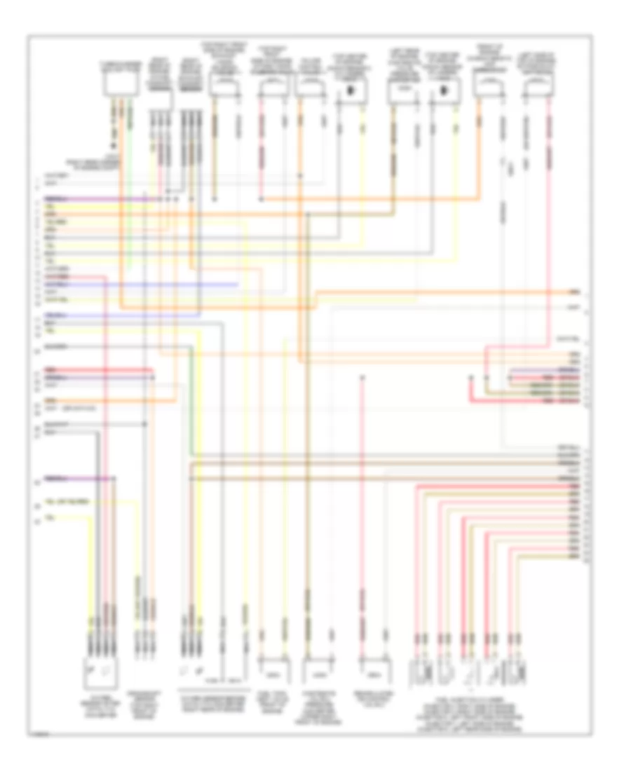
4.4L Twin Turbo, Engine Performance Wiring Diagram (1 of 5) for BMW X5 M 2013

List of elements for 4.4L Twin Turbo, Engine Performance Wiring Diagram (1 of 5) for BMW X5 M 2013:
- (or 6)
- (right rear corner of engine compt) x7517
- Air mass flow sensor (top left front of engine)
- Charge air pressure sensor
- Dme control unit (right rear of engine compt)
- Dme relay
- Electric throttle valve actuator (front of engine)
- Engine coolant temperature sensor (front of engine)
- Exhaust temperature sensor
- Fuel tank vent valve 2 (right front of engine compt)
- Fuse 250a
- Fuse box (under left side of rear compt floor)
- Fuse f35 30a
- Fuse f36 30a
- Fuse f4 10a
- Fuse f42 30a
- Fuse f43 30a
- Hot at all times
- Intake air temperature/ intake manifold pressure sensor (on intake manifold, right side)
- Junction box (under right side of dash)
- Oil condition sensor (top right of engine)
- Oil pressure switch (front of engine)
- Rail pressure sensor
- Red
- Starting/ charging system
- Volume control valve relay
- X10001
- X11002
- X11005
- X11006
- X16824
- X60002
- X6011
- X6021
- X6031
- X7517 (right rear corner of engine compt)
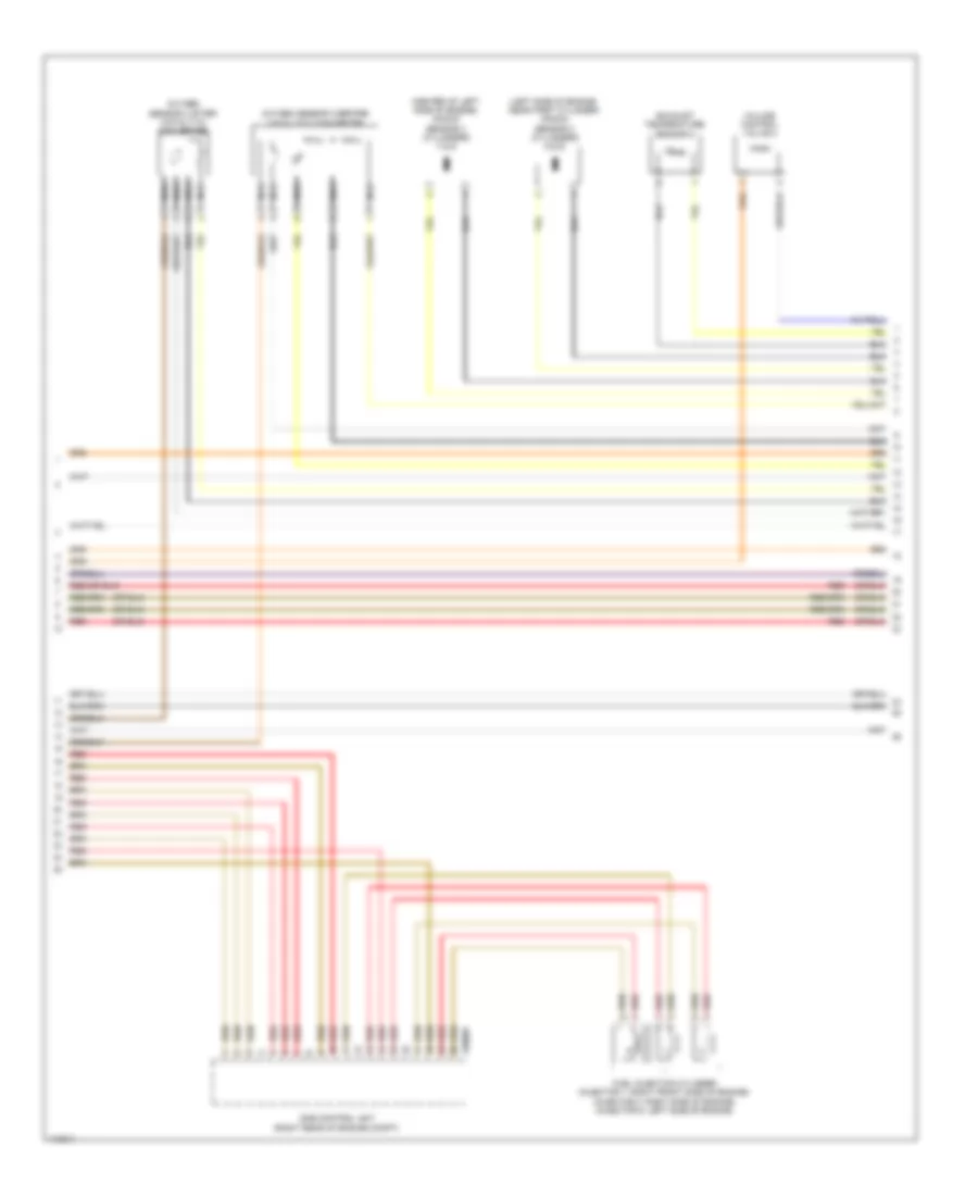
4.4L Twin Turbo, Engine Performance Wiring Diagram (2 of 5) for BMW X5 M 2013
List of elements for 4.4L Twin Turbo, Engine Performance Wiring Diagram (2 of 5) for BMW X5 M 2013:
- (front of engine) characteristic map thermostat
- (left rear of engine) wastegate valve pressure converter
- (left side of top of engine) bypass blow off valve
- (right rear of engine) exhaust camshaft sensor
- (right rear of engine) intake camshaft sensor
- (top center of engine) knock sensor (cylinders 1 & 2)
- (top center of engine) knock sensor 2 (cylinders 3 & 4)
- (top right front side of engine) exhaust vanos solenoid valve
- (top right front side of engine) intake vanos solenoid valve
- Crankshaft sensor (top right front of engine)
- Fuel injection cylinder (injector 2: right side of engine) (injector 4: right side of engine) (injector 5: left front side of engine) (injector 7: left side of engine) (injector 8: left rear side of engine)
- Fuel tank vent valve (front of engine)
- Nca
- Oxygen sensor after catalytic converter
- Oxygen sensor before catalytic converter (right rear of engine)
- Recirculated air control valve 2
- Red
- Turbocharger coolant pump
- Volume control valve
- Wastegate valve 2 pressure converter (upper right front of engine)
- X6011
- X7517 (right rear corner of engine compt)
4.4L Twin Turbo, Engine Performance Wiring Diagram (3 of 5) for BMW X5 M 2013
List of elements for 4.4L Twin Turbo, Engine Performance Wiring Diagram (3 of 5) for BMW X5 M 2013:
- (center of left side of engine) knock sensor 4 (cylinders 7 & 8)
- (left side of engine, near first cylinder) knock sensor 3 (cylinders 5 & 6)
- Dme control unit (right rear of engine compt)
- Exhaust temperature sensor 2
- Fuel injection cylinder (injector 1: right front side of engine) (injector 3: right side of engine) (injector 6: left side of engine)
- Nca
- Oxygen sensor 2 after catalytic converter
- Oxygen sensor 2 before catalytic converter
- Red
- Volume control valve 2
- X60005
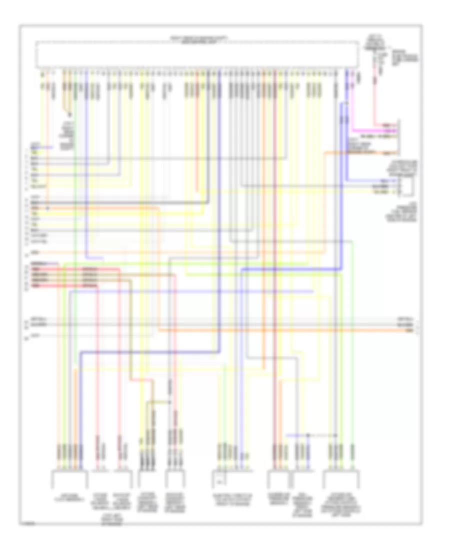
4.4L Twin Turbo, Engine Performance Wiring Diagram (4 of 5) for BMW X5 M 2013
List of elements for 4.4L Twin Turbo, Engine Performance Wiring Diagram (4 of 5) for BMW X5 M 2013:
- (right rear of engine compt) dme control unit
- (top left front side of engine)
- Air mass flow sensor 2
- Charge air pressure sensor 2
- Electric throttle valve actuator 2 (front of engine)
- Engine electronics fuse carrier box
- Exhaust camshaft sensor 2 (left rear of engine)
- Exhaust vanos solenoid valve 2
- Fuse f07 15a x8681
- Hot w/ terminal 30g relay energized
- Intake air temperature/ intake manifold pressure sensor 2 (on intake manifold, left side)
- Intake camshaft sensor 2 (left rear of engine)
- Intake vanos solenoid valve 2
- Intercooler coolant pump (right front of engine compt)
- Low pressure fuel sensor (center of left side of engine)
- Nca
- Rail pressure sensor 2 (front left side of engine)
- Red
- X60004
- X7517 (right rear corner of engine compt)
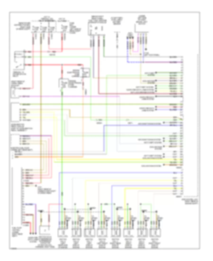
4.4L Twin Turbo, Engine Performance Wiring Diagram (5 of 5) for BMW X5 M 2013
List of elements for 4.4L Twin Turbo, Engine Performance Wiring Diagram (5 of 5) for BMW X5 M 2013:
- (at battery) intelligent battery sensor
- (behind right rear wheel) fuel tank leakage diagnostic module
- (right rear of cargo area) exhaust flap
- (under left side of dash) brake light switch
- (under right rear seat)
- Acceleration pedal module (part of acceleration pedal assembly)
- Air conditioning system
- Anti- theft system
- Anti-lock brakes system
- Anti-theft system
- Computer data lines system
- Cooling fans system
- Dme control unit (right rear of engine compt)
- Electric fuel pump (under left rear seat)
- Engine electronics fuse carrier
- Fuel pump control
- Fuse box (under left side of rear compt floor)
- Fuse f01 30a
- Fuse f02 30a
- Fuse f105 20a
- Fuse f122 5a
- Fuse f128 5a
- Fuse f176 80a
- Hot at all times
- Hot w/ terminal 30g relay energized
- Ignition coil 1 (right front side of engine)
- Ignition coil 2 (right side of engine)
- Ignition coil 3 (right side of engine)
- Ignition coil 4 (right rear side of engine)
- Ignition coil 5 (left front side of engine)
- Ignition coil 6 (left side of engine)
- Ignition coil 7 (left side of engine)
- Ignition coil 8 (left rear side of engine)
- Ignition coils interference suppression capacitor (in ignition coil harness, right side)
- Nca
- Rear power distribution box (right side of rear compt)
- Red
- Terminal 15 power saving relay
- To spark plug
- X102720
- X11012
- X11013
- X11016
- X1108 (left kick panel)
- X13663
- X14020
- X151 (right rear of under-floor compt in cargo area)
- X60001
- X60003
- X6011
- X60541
- X64108
- X64561
- X64562
- X64563
- X64564