ENGINE PERFORMANCE
3.8L VIN 1
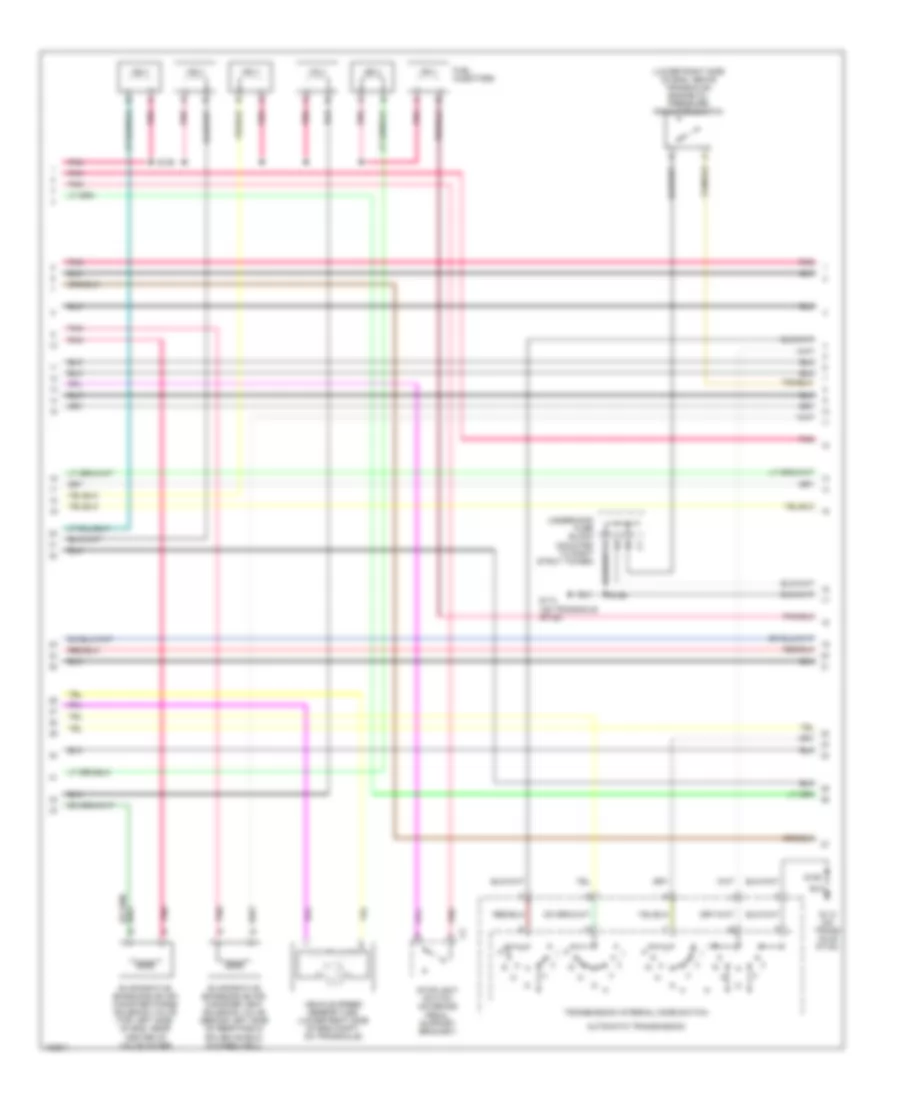
3.8L VIN 1, Engine Performance Wiring Diagram (1 of 4) for Buick Regal GS 2004

List of elements for 3.8L VIN 1, Engine Performance Wiring Diagram (1 of 4) for Buick Regal GS 2004:
- (ign harn, top of eng, near ign control module)
- (not used)
- (on trans- axle stud)
- (pin 11 not used)
- (pin 14-15 not used)
- (pin 21-27 not used)
- (pin 40-42 not used)
- (pin 49-52 not used)
- (pin 66-67 not used)
- (right side of engine, on ignition contrl module bracket)
- (vin 1)
- 1-2 ss valve control
- 18x ref signal
- 2-3 ss valve control
- 3x ref signal
- A/t iss sensor high
- A/t iss sensor low
- Abs system
- Camshaft position sensor (cmp) (front of engine)
- Cmp signal
- Cooling fans system
- Crankshaft position sensor (ckp) (front of eng, behind harmonic balancer)
- Cruise control system
- Cruise disable output
- Data link connector (dlc) (under left side of dash, right of steering column)
- Ecm fuse 22 10a
- Egr val control (gnd)
- Elek ign fuse 25 15a
- Eng emis fuse 30 10a
- Evap purge val control
- F/injr fuse 28 15a
- Fuel inj 1 control
- Fuel inj 2 control
- Fuel inj 4 control
- Fuel inj 5 control
- Fuel inj 6 control
- G111
- G113
- High speed fans control
- Hos1 low
- Hos2 low
- Hot at all times
- Hot in off, run, or start
- Hot in run or start
- I/p fuse block (behind right side of dash, in right door opening)
- Iac coil b high
- Iat sensor ground
- Ic control
- Ign 0 fuse 10a
- Ignition control
- Ignition control module (icm) (top front of eng)
- Ignition wake up power
- Knock sensor bank 1 (left side of eng, in front of starter)
- Knock sensor bank 2 (right side of eng, below exhaust manifold)
- Knock sensor signal 1
- Knock sensor signal 2
- Low ref
- Low speed fans control
- Maf signal
- Map sensor
- Pcm ground
- Pnk
- Pnk p
- Power (battery)
- Powertrain control module (pcm) (left front side of eng compt, in air cleaner assembly)
- Ref low
- Requested torque sig
- S106
- S144
- S145
- S270
- Sensor grd
- Sensor ground
- Serial data (class 2)
- Spark plugs
- Splice pack sp205
- Tcc brake switch input
- Tp sensor
- Tr switch input b
- Underhood fuse block (mounted to right strut tower)
- Vss high
- Vss low
- Vss output
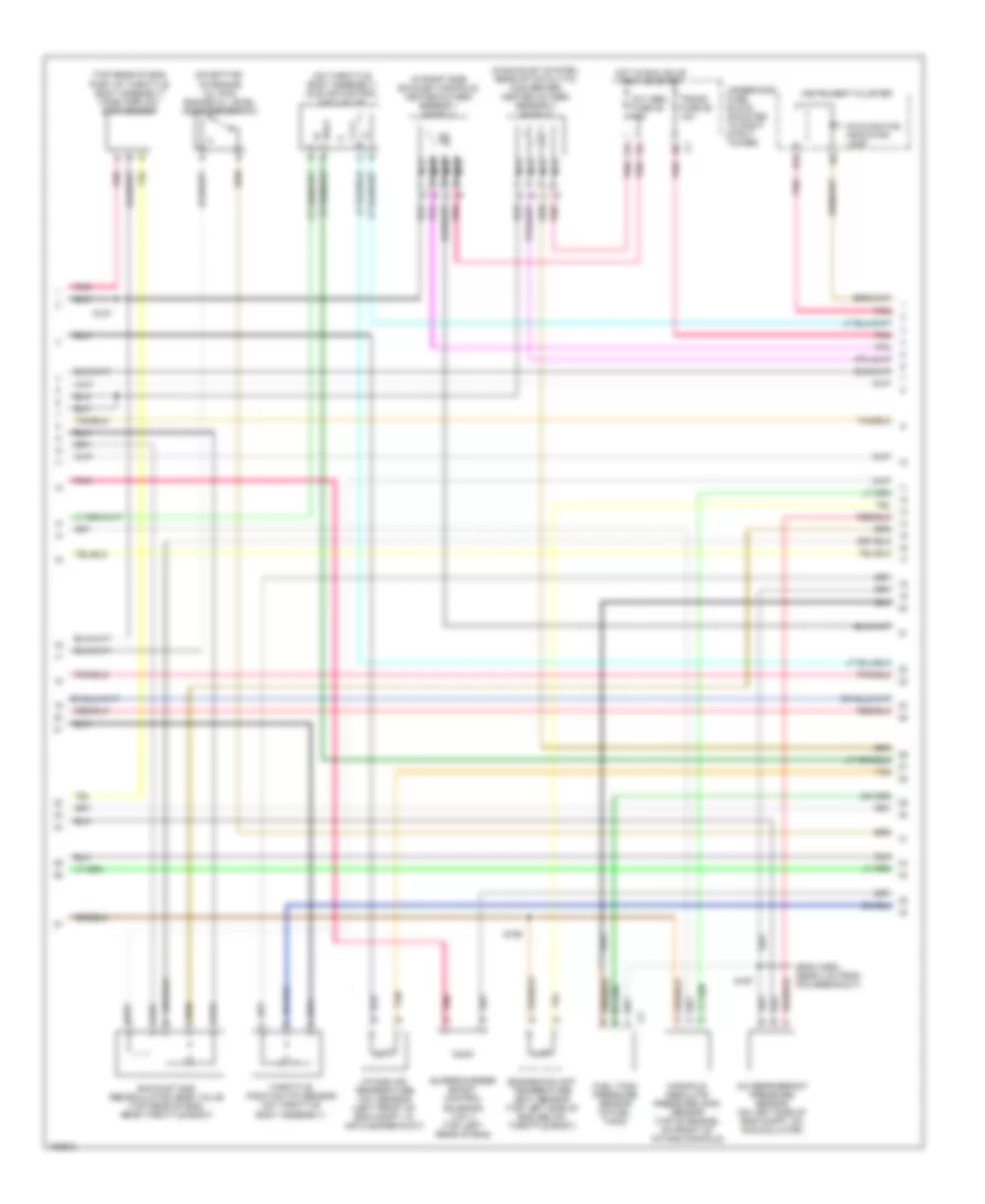
3.8L VIN 1, Engine Performance Wiring Diagram (2 of 4) for Buick Regal GS 2004
List of elements for 3.8L VIN 1, Engine Performance Wiring Diagram (2 of 4) for Buick Regal GS 2004:
- (lower right side of eng, above transaxle) engine oil pressure indicator switch
- (on transaxle stud)
- Automatic transmission
- Evaporative emissions (evap) canister purge solenoid valve (top left side of eng, near center of valve cover)
- Evaporative emissions (evap) canister vent solenoid valve (behind left side of rear fascia splash shield, in wheelwell)
- Fuel injectors
- G113
- G113 (on trans- axle stud)
- Pnk
- S106
- S109
- Stoplight switch (on brake pedal support bracket)
- Transmission internal mode switch
- Underhood fuse block (mounted to right strut tower)
- Vehicle speed sensor (vss) (lower right side of eng compt, on transaxle)
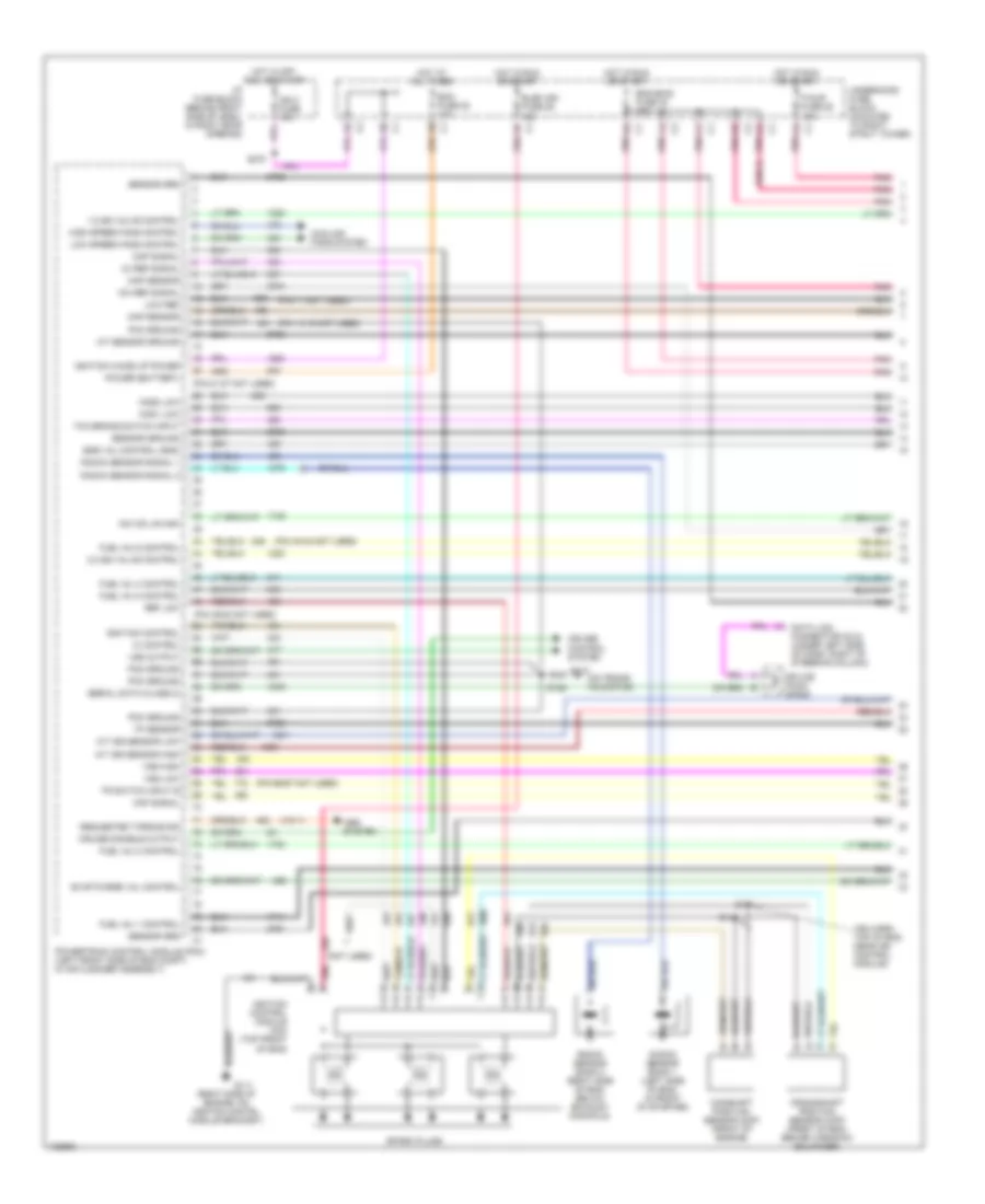
3.8L VIN 1, Engine Performance Wiring Diagram (3 of 4) for Buick Regal GS 2004
List of elements for 3.8L VIN 1, Engine Performance Wiring Diagram (3 of 4) for Buick Regal GS 2004:
- (eng harn, near 4 cm from pcm breakout)
- (in exhaust system, rear of catalytic converter) heated oxygen sensor 2 (ho2s 2)
- (in right side exhaust manifold) heated oxygen sensor 1 (ho2s 1)
- (on bottom of engine oil pan) engine oil level indicator switch
- (on throttle body assembly) idle air control (iac) valve
- (top rear of eng, part of throttle body assembly) mass airflow (maf) sensor
- A/c refrigerant pressure sensor (on left side of eng compt, on accumulator)
- B12
- D pnk
- Engine coolant temperature (ect) sensor (top left side of eng, below throttle body)
- Exhaust gas recirculation (egr) valve (top rear of eng, near throttle body)
- Fuel tank pressure sensor (in fuel tank)
- Hot in run, bulb test or start
- Instrument cluster
- Intake air temperature (iat) sensor (left front of eng compt, in air cleaner duct)
- Malfunction indicator lamp
- Manifold absolute pressure (map) sensor (top of engine, on front of intake manifold)
- Nca
- Oxy sen fuse 29 15a
- Pnk
- S167
- S186
- S187
- Supercharger boost control solenoid (vin 1) (top left rear of eng)
- Tan
- Throttle position (tp) sensor (on throttle body assembly)
- Trans fuse 26 10a
- Underhood fuse block (mounted to right strut tower)
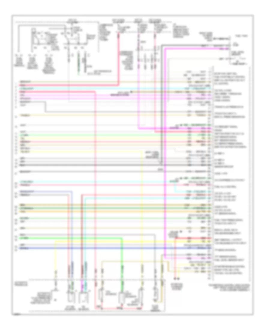
3.8L VIN 1, Engine Performance Wiring Diagram (4 of 4) for Buick Regal GS 2004
List of elements for 3.8L VIN 1, Engine Performance Wiring Diagram (4 of 4) for Buick Regal GS 2004:
- (body harn, under rear seat)
- (fuel pump prime terminal)
- (on transaxle stud)
- (pin 12-15 not used)
- (pin 31-32 not used)
- (pin 40-41 not used)
- (pin 51-54 not used)
- (pin 6 & 8 not used)
- (pin 62 & 64-65 not used)
- (pin 70-75 not used)
- (right side of rear shelf) g402
- (vin 1)
- 1-2 shift solenoid
- 2-3 shift solenoid
- 5v ref a
- A/c compress clutch rly
- A/c refrig press signal
- A/c request signal
- A/c system
- A/t iss solenoid
- A11
- Anti-lock brakes system
- Automatic transaxle
- Automatic transaxle fluid pressure manual valve position switch
- Boost ctrl sol ctrl
- Cluster fuse 10a
- Crank
- Crank signal fuse 10a
- Cruise control system
- Cruise engaged input
- D10
- Delivered torque sig
- Ect sensor signal
- Egr pintle position signal
- Egr val ign positive volt
- Eng oil level ind in
- Eng oil press sensor sig
- Evap can vent sol
- F/pmp fuse 35 15a
- F/pmp spd cont relay (vin 1 w/ fog lights)
- F/pump relay
- Fluid temp sensor
- Fuel inj 3 control
- Fuel level sensor
- Fuel level sensor input
- Fuel pump
- Fuel pump relay control
- Fuel tank
- Fuel tank press signal
- G113
- Gen terminal l output
- Ho2s 1 htr
- Ho2s 1 signal
- Ho2s 2 htr
- Ho2s 2 signal
- Hot at all times
- Hot in run or start
- Hot in start
- I/p fuse block (behind right side of dash, in right door opening)
- Iac coil a high
- Iac coil a low
- Iac coil b low
- Iat sensor signal
- Ignition positive volt (2)
- Map sensor signal
- Mil control
- Pc sol valve high
- Pc sol valve low
- Pcm,bcm ign relay fuse 10a
- Pnk
- Powertrain control module (pcm) (left front side of eng compt, in air cleaner assembly)
- Ps solenoid
- Red
- S106
- S234
- S409
- Sensor ground
- Starter enable control
- Starting/ charging system
- Tan
- Tan b
- Tcc release switch input
- Tcc sol valve control
- Tcc solenoid
- Tft sensor signal
- Tp sens or signal
- Tr switch input a
- Tr switch input c
- Trans fluid press sw b
- Underhood accessory fuse block (mounted to right strut tower)
- Underhood fuse block (mounted to right strut tower)
3.8L VIN K
3.8L VIN K, Engine Performance Wiring Diagram (1 of 4) for Buick Regal GS 2004
List of elements for 3.8L VIN K, Engine Performance Wiring Diagram (1 of 4) for Buick Regal GS 2004:
- (ign harn, top of eng, near ign control module)
- (not used)
- (on trans- axle stud)
- (pin 11 not used)
- (pin 14-15 not used)
- (pin 21-27 not used)
- (pin 40-42 not used)
- (pin 49-52 not used)
- (pin 66-67 not used)
- (right side of engine, on ignition contrl module bracket)
- (vin 1)
- 1-2 ss valve control
- 18x ref signal
- 2-3 ss valve control
- 3x ref signal
- A/t iss sensor high
- A/t iss sensor low
- Abs system
- Camshaft position sensor (cmp) (front of engine)
- Cmp signal
- Cooling fans system
- Crankshaft position sensor (ckp) (front of eng, behind harmonic balancer)
- Cruise control system
- Cruise disable output
- Data link connector (dlc) (under left side of dash, right of steering column)
- Ecm fuse 22 10a
- Egr val control (gnd)
- Elek ign fuse 25 15a
- Eng emis fuse 30 10a
- Evap purge val control
- F/injr fuse 28 15a
- Fuel inj 1 control
- Fuel inj 2 control
- Fuel inj 4 control
- Fuel inj 5 control
- Fuel inj 6 control
- G111
- G113
- High speed fans control
- Hos1 low
- Hos2 low
- Hot at all times
- Hot in off, run, or start
- Hot in run or start
- I/p fuse block (behind right side of dash, in right door opening)
- Iac coil b high
- Iat sensor ground
- Ic control
- Ign 0 fuse 10a
- Ignition control
- Ignition control module (icm) (top front of eng)
- Ignition wake up power
- Knock sensor bank 1 (left side of eng, in front of starter)
- Knock sensor bank 2 (right side of eng, below exhaust manifold)
- Knock sensor signal 1
- Knock sensor signal 2
- Low ref
- Low speed fans control
- Maf signal
- Map sensor
- Pcm ground
- Pnk
- Pnk p
- Power (battery)
- Powertrain control module (pcm) (left front side of eng compt, in air cleaner assembly)
- Ref low
- Requested torque sig
- S106
- S144
- S145
- S270
- Sensor grd
- Sensor ground
- Serial data (class 2)
- Spark plugs
- Splice pack sp205
- Tcc brake switch input
- Tp sensor
- Tr switch input b
- Underhood fuse block (mounted to right strut tower)
- Vss high
- Vss low
- Vss output
3.8L VIN K, Engine Performance Wiring Diagram (2 of 4) for Buick Regal GS 2004
List of elements for 3.8L VIN K, Engine Performance Wiring Diagram (2 of 4) for Buick Regal GS 2004:
- (lower right side of eng, above transaxle) engine oil pressure indicator switch
- (on transaxle stud)
- Automatic transmission
- Evaporative emissions (evap) canister purge solenoid valve (top left side of eng, near center of valve cover)
- Evaporative emissions (evap) canister vent solenoid valve (behind left side of rear fascia splash shield, in wheelwell)
- Fuel injectors
- G113
- G113 (on trans- axle stud)
- Pnk
- S106
- S109
- Stoplight switch (on brake pedal support bracket)
- Transmission internal mode switch
- Underhood fuse block (mounted to right strut tower)
- Vehicle speed sensor (vss) (lower right side of eng compt, on transaxle)
3.8L VIN K, Engine Performance Wiring Diagram (3 of 4) for Buick Regal GS 2004
List of elements for 3.8L VIN K, Engine Performance Wiring Diagram (3 of 4) for Buick Regal GS 2004:
- (eng harn, near 4 cm from pcm breakout)
- (in exhaust system, rear of catalytic converter) heated oxygen sensor 2 (ho2s 2)
- (in right side exhaust manifold) heated oxygen sensor 1 (ho2s 1)
- (on bottom of engine oil pan) engine oil level indicator switch
- (on throttle body assembly) idle air control (iac) valve
- (top rear of eng, part of throttle body assembly) mass airflow (maf) sensor
- A/c refrigerant pressure sensor (on left side of eng compt, on accumulator)
- B12
- D pnk
- Engine coolant temperature (ect) sensor (top left side of eng, below throttle body)
- Exhaust gas recirculation (egr) valve (top rear of eng, near throttle body)
- Fuel tank pressure sensor (in fuel tank)
- Hot in run, bulb test or start
- Instrument cluster
- Intake air temperature (iat) sensor (left front of eng compt, in air cleaner duct)
- Malfunction indicator lamp
- Manifold absolute pressure (map) sensor (top of engine, on front of intake manifold)
- Nca
- Oxy sen fuse 29 15a
- Pnk
- S167
- S186
- S187
- Supercharger boost control solenoid (vin 1) (top left rear of eng)
- Tan
- Throttle position (tp) sensor (on throttle body assembly)
- Trans fuse 26 10a
- Underhood fuse block (mounted to right strut tower)
3.8L VIN K, Engine Performance Wiring Diagram (4 of 4) for Buick Regal GS 2004
List of elements for 3.8L VIN K, Engine Performance Wiring Diagram (4 of 4) for Buick Regal GS 2004:
- (body harn, under rear seat)
- (fuel pump prime terminal)
- (on transaxle stud)
- (pin 12-15 not used)
- (pin 31-32 not used)
- (pin 40-41 not used)
- (pin 51-54 not used)
- (pin 6 & 8 not used)
- (pin 62 & 64-65 not used)
- (pin 70-75 not used)
- (right side of rear shelf) g402
- (vin 1)
- 1-2 shift solenoid
- 2-3 shift solenoid
- 5v ref a
- A/c compress clutch rly
- A/c refrig press signal
- A/c request signal
- A/c system
- A/t iss solenoid
- A11
- Anti-lock brakes system
- Automatic transaxle
- Automatic transaxle fluid pressure manual valve position switch
- Boost ctrl sol ctrl
- Cluster fuse 10a
- Crank
- Crank signal fuse 10a
- Cruise control system
- Cruise engaged input
- D10
- Delivered torque sig
- Ect sensor signal
- Egr pintle position signal
- Egr val ign positive volt
- Eng oil level ind in
- Eng oil press sensor sig
- Evap can vent sol
- F/pmp fuse 35 15a
- F/pmp spd cont relay (vin 1 w/ fog lights)
- F/pump relay
- Fluid temp sensor
- Fuel inj 3 control
- Fuel level sensor
- Fuel level sensor input
- Fuel pump
- Fuel pump relay control
- Fuel tank
- Fuel tank press signal
- G113
- Gen terminal l output
- Ho2s 1 htr
- Ho2s 1 signal
- Ho2s 2 htr
- Ho2s 2 signal
- Hot at all times
- Hot in run or start
- Hot in start
- I/p fuse block (behind right side of dash, in right door opening)
- Iac coil a high
- Iac coil a low
- Iac coil b low
- Iat sensor signal
- Ignition positive volt (2)
- Map sensor signal
- Mil control
- Pc sol valve high
- Pc sol valve low
- Pcm,bcm ign relay fuse 10a
- Pnk
- Powertrain control module (pcm) (left front side of eng compt, in air cleaner assembly)
- Ps solenoid
- Red
- S106
- S234
- S409
- Sensor ground
- Starter enable control
- Starting/ charging system
- Tan
- Tan b
- Tcc release switch input
- Tcc sol valve control
- Tcc solenoid
- Tft sensor signal
- Tp sens or signal
- Tr switch input a
- Tr switch input c
- Trans fluid press sw b
- Underhood accessory fuse block (mounted to right strut tower)
- Underhood fuse block (mounted to right strut tower)