ENGINE PERFORMANCE
4.3L
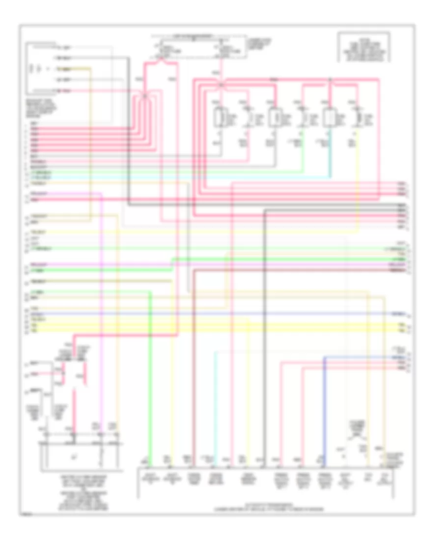
4.3L (VIN W), Engine Performance Wiring Diagrams (1 of 4) for Chevrolet Chevy Van G3500 1996

List of elements for 4.3L (VIN W), Engine Performance Wiring Diagrams (1 of 4) for Chevrolet Chevy Van G3500 1996:
- (not used)
- A/c coil ground
- A/c compressor clutch relay
- Camshaft position sensor (part of distributor, top rear of engine)
- Coil
- Coil a high
- Coil a low
- Coil b high
- Coil b low
- Crankshaft position sensor (lower front of engine, near crankshaft)
- Egr sol posit signal
- Egr solenoid output
- Evaporative canister purge solenoid valve (right side of engine)
- G119 (engine harness at generator bracket; right front of engine)
- Heated oxygen sensor, left pre-converter (in exhaust pipe, in front of catalytic converter)
- Heated oxygen sensor, right post-converter (in exhaust pipe, in back of catalytic converter)
- Heated oxygen sensor, right pre-converter (in exhaust pipe, in front of catalytic converter)
- Idle air control valve motor (top right side of engine)
- If equipped
- Ignition
- Inj no.1 ctrl
- Inj no.2 ctrl
- Inj no.3 ctrl
- Inj no.4 ctrl
- Inj no.5 ctrl
- Inj no.6 ctrl
- Knock sens signal
- Knock sensor (top rear of engine)
- Maf signal
- Map sens signal
- Nca
- Pnk
- Pnk c
- Return
- Sensor signal
- Shift sol. a output
- Shift sol. b output
- Shift sol. output (3/2)
- Signal
- Solenoid output
- Solid state
- Tan
- Tcc pwm sol ctrl
- Tcc solenoid output
- Trans temp sens signal
- Underhood fuse-relay center
- Vehicle control module (vcm) (engine compartment, left fender)
- Vss signal output
- W/gvw over lbs.
- W/gvw under 8500 lbs. only
- W/gvw under lbs.
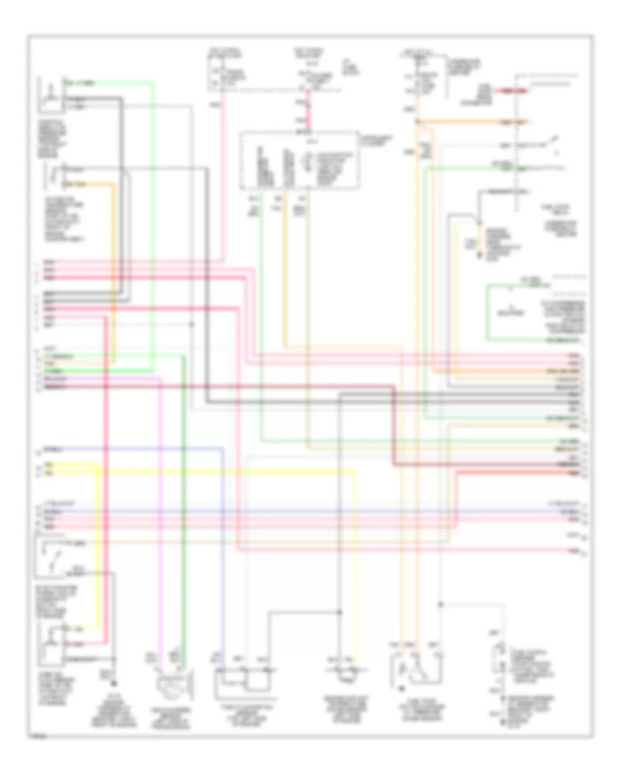
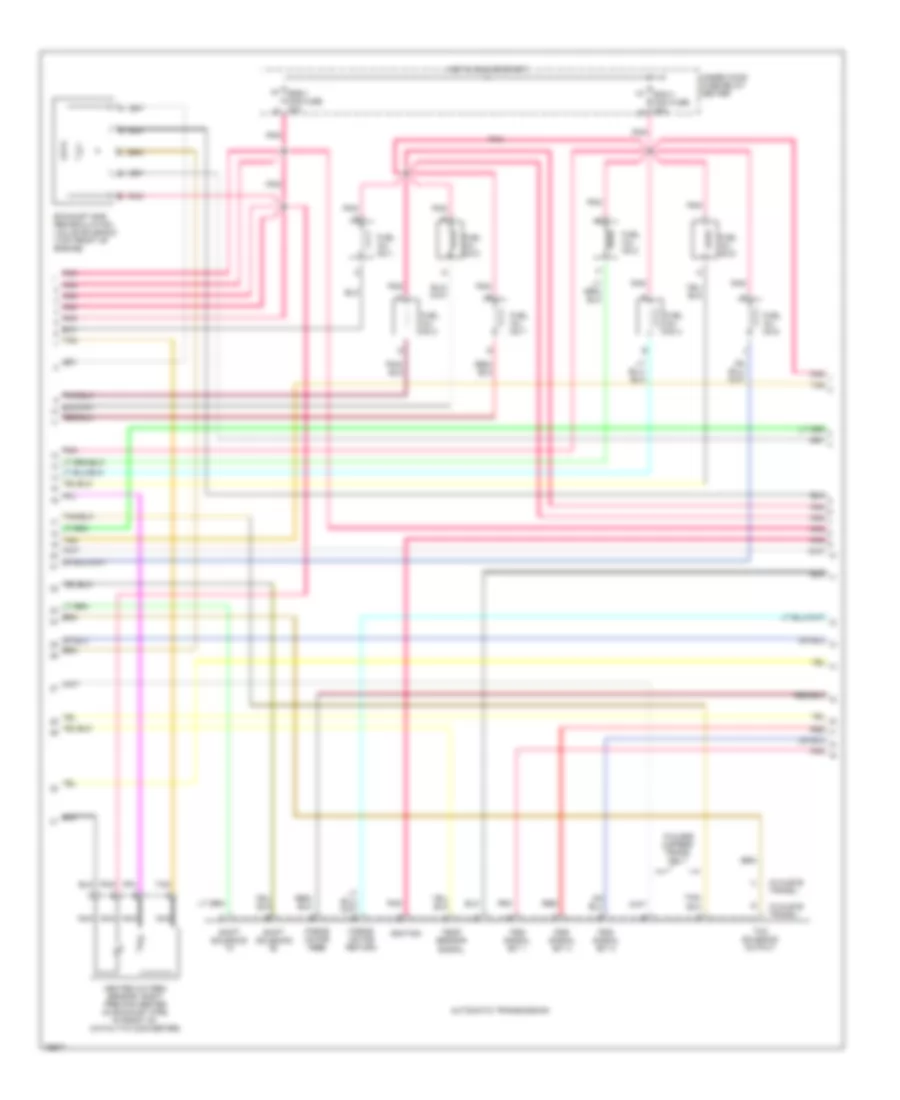
4.3L (VIN W), Engine Performance Wiring Diagrams (2 of 4) for Chevrolet Chevy Van G3500 1996
List of elements for 4.3L (VIN W), Engine Performance Wiring Diagrams (2 of 4) for Chevrolet Chevy Van G3500 1996:
- (w/4l60-e u trans.)
- (w/4l80-e s trans.)
- Automatic transmission (under center of vehicle, attached to rear of engine)
- Eng-1 mini fuse 20a
- Exhaust gas recirculation valve solenoid (right side of engine)
- Force motor feed
- Force motor return
- Fuel inj. no.1
- Fuel inj. no.2
- Fuel inj. no.3
- Fuel inj. no.4
- Fuel inj. no.5
- Fuel inj. no.6
- H7 ecm-1 mini fuse 20a
- Heated oxygen sensor left post converter (gvw under 8500 lbs.) or heated oxygen sensor post converter (gvw over 8500 lbs.) (in exhaust pipe, in back of catalytic converter)
- Hot in run or start
- Nca
- Note: fuel injectors are located in central sfi, mounted on lower portion of intake manifold
- Pnk
- Pnk pnk pnk
- Press. switch signal bit 1
- Press. switch signal bit 2
- Press. switch signal bit 3
- Red
- Shift sol. output 2/3
- Shift solenoid "a"
- Shift solenoid "b"
- Tan
- Tcc sol.
- Tcc sol. output
- Temp. sensor signal
- Under hood fuse-relay center
- W/4l60e 4-speed trans. only
- W/gvw over lbs.
- W/gvw under 8500 lbs.
- W/gvw under lbs.
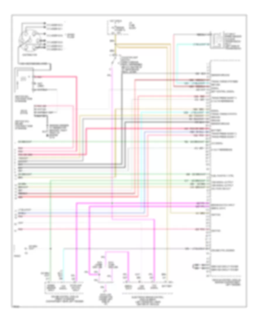
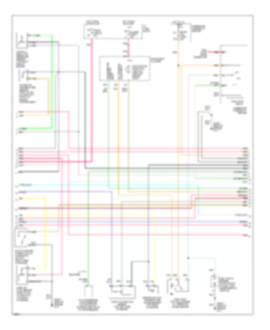
4.3L (VIN W), Engine Performance Wiring Diagrams (3 of 4) for Chevrolet Chevy Van G3500 1996
List of elements for 4.3L (VIN W), Engine Performance Wiring Diagrams (3 of 4) for Chevrolet Chevy Van G3500 1996:
- (engine harness at generator bracket; right front of engine) g119
- (engine harness, near thermostat housing) g125
- A/c compressor high pressure cutoff switch (on rear portion of a/c compressor)
- B14
- B17
- Ecm-b mini fuse 20a
- Engine coolant temperature gauge sensor (left side of engine)
- Evap canister purge vacuum diagnostic switch (right side of engine)
- F11
- Fuel pump & sender (pump shown) (in fuel tank under rear of vehicle)
- Fuel pump prime connector
- Fuel pump relay
- Fuel pump switch & engine oil pressure gauge sensor
- G119 (engine harness at generator bracket, right front of engine)
- G12
- Gauge input oil pressure
- Gauges fuse 4 10a
- Hot at all times
- Hot in run or start
- Hot in run, start & off
- I/p fuse block
- If equipped
- Input odometer speedometer/
- Instrument cluster
- Intake air temperature sensor (part of air intake duct, front of engine compartment)
- Malfunction indicator lamp (mil) "service engine soon"
- Manifold absolute pressure sensor (top right side of engine)
- Mass air flow sensor (part of air intake duct, top front of engine)
- Pnk
- Red
- Tan
- Tan b
- Throttle position sensor (top left side of engine)
- Trans fuse 20 10a
- Underhood fuse-relay center
- Vehicle speed sensor (left side of transmission)
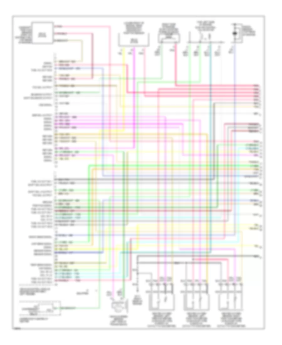
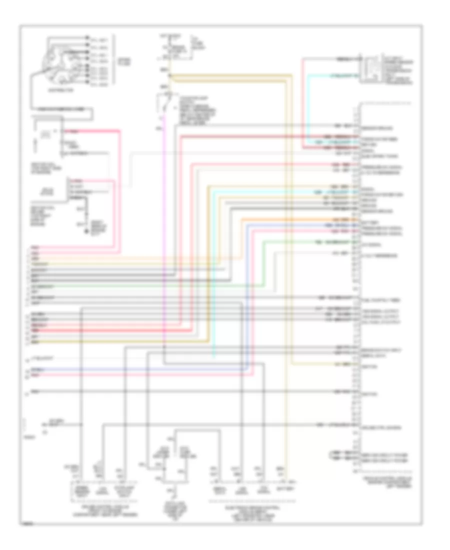
4.3L (VIN W), Engine Performance Wiring Diagrams (4 of 4) for Chevrolet Chevy Van G3500 1996
List of elements for 4.3L (VIN W), Engine Performance Wiring Diagrams (4 of 4) for Chevrolet Chevy Van G3500 1996:
- (engine harness at generator bracket; right front of engine) g119
- (not used)
- 5 volt reference
- 5 volts reference
- A/c signal
- A/t input speed sensor (w/4l80-e transmission only) (left side of transmission)
- Battery
- Brake switch input
- Cruise control module (front of engine compartment near left fender)
- Cruise ctrl sig-eng
- Cylinder no.1
- Cylinder no.2
- Cylinder no.3
- Cylinder no.4
- Cylinder no.5
- Cylinder no.6
- Data link connector (under left side of i/p)
- Distributor
- Electronic brake control module (ebcm) (left frame rail near center of vehicle)
- Est control signal
- Fuel pump rly ctrl
- Ground
- Gvw over 8500 lbs.
- Gvw under 8500 lbs
- High voltage coil wire
- Hot in run
- I/p fuse block
- Ignition
- Ignition coil (top right side of engine)
- Ignition coil driver (top right side of engine)
- M4 brake fuse 18 10a n3
- Mal func ind out
- Pnk
- Pnk a
- Radio
- Red
- Return
- Sensor ground
- Serial data
- Service circuit power
- Signal
- Solid state
- Spark plugs
- Speed sensor input
- Stoplamp switch input
- Tcc signal
- Tcc/stoplamp switch (open w/brake pedal depressed) (below center of i/p, near brake pedal lever)
- Trans press sig-bit 1
- Trans press sig-bit 2
- Trans press sig-bit 3
- Trans. force mtr feed
- Trans. force mtr rtn
- Vcm signal
- Vehicle control module (engine compartment, left fender)
- Vss signal
- Vss signal output
5.0L
5.0L (VIN M), Engine Performance Wiring Diagrams (1 of 4) for Chevrolet Chevy Van G3500 1996
List of elements for 5.0L (VIN M), Engine Performance Wiring Diagrams (1 of 4) for Chevrolet Chevy Van G3500 1996:
- (lower front of engine, near crankshaft) crankshaft position sensor
- (right side of engine) evap canister purge solenoid valve
- (top left side of engine) idle air control valve motor
- A/c compressor clutch relay
- Camshaft position sensor (part of distributor, top rear of engine)
- Coil
- Coil "a" hi
- Coil "a" lo
- Coil "b" hi
- Coil "b" lo
- Egr sol output
- Fuel inj out no.1
- Fuel inj out no.2
- Fuel inj out no.3
- Fuel inj out no.4
- Fuel inj out no.5
- Fuel inj out no.6
- Fuel inj out no.7
- Fuel inj out no.8
- G117 (right rear of engine)
- Ground
- Heated oxygen sensor, left post-converter (in exhaust pipe in back of catalytic converter)
- Heated oxygen sensor, left pre-converter (in exhaust pipe in front of catalytic converter)
- Heated oxygen sensor, right post-converter (in exhaust pipe in back of catalytic converter)
- If equipped
- Ignition
- Knock sens signal
- Knock sensor (top rear of engine)
- Maf signal
- Map sens signal
- Nca
- Pnk
- Pnk c
- Position signal
- Return
- Sensor signal
- Shift sol a output
- Shift sol b output
- Shift solenoid output
- Signal
- Solenoid output
- Solid state
- Tan
- Tcc sol output
- Temp sens signal
- Underhood fuse-relay center
- Vehicle control module (engine compartment, left fender)
- Vehicle speed sensor (left side of transmission)
- Vss signal
5.0L (VIN M), Engine Performance Wiring Diagrams (2 of 4) for Chevrolet Chevy Van G3500 1996
List of elements for 5.0L (VIN M), Engine Performance Wiring Diagrams (2 of 4) for Chevrolet Chevy Van G3500 1996:
- (w/4l60-e trans.)
- (w/4l80-e trans.)
- Automatic transmission
- Ecm-1 mini fuse 20a
- Exhaust gas recirculation valve solenoid (top front of engine)
- Force motor feed
- Force motor return
- Fuel inj. no.1
- Fuel inj. no.2
- Fuel inj. no.3
- Fuel inj. no.4
- Fuel inj. no.5
- Fuel inj. no.6
- Fuel inj. no.7
- Fuel inj. no.8
- Heated oxygen sensor, right pre-converter (in exhaust pipe in front of catalytic converter)
- Hot in run or start
- Ignition
- K7 eng-1 mini fuse 20a l8
- Nca
- Pnk
- Pnk tan
- Pss signal bit 1
- Pss signal bit 2
- Pss signal bit 3
- Red
- Shift solenoid "a"
- Shift solenoid "b"
- Tan
- Tcc solenoid output
- Temp sensor signal
- Under hood fuse-relay center
- W/4l60e 4-speed trans. only
5.0L (VIN M), Engine Performance Wiring Diagrams (3 of 4) for Chevrolet Chevy Van G3500 1996
List of elements for 5.0L (VIN M), Engine Performance Wiring Diagrams (3 of 4) for Chevrolet Chevy Van G3500 1996:
- (right rear of engine) g117
- A/c compressor high pressure cutoff switch (on rear portion of a/c compressor)
- B14
- B17
- Ecm-b mini fuse 20a
- Engine coolant temperature gauge sensor (top front of engine)
- Evap canister purge vacuum diagnostic switch (right side of engine)
- F11
- Fuel pump & sender (pump shown) (in fuel tank under rear of vehicle)
- Fuel pump prime connector
- Fuel pump relay
- Fuel pump switch & engine oil pressure gauge sensor
- G12
- Gauges fuse 4 10a
- Hot at all times
- Hot in run or start
- Hot in run, start & off
- I/p fuse block
- If equipped
- Instrument cluster
- Intake air temperature sensor (part of air intake duct, front of engine compartment)
- Malfunction indicator lamp (mil) "service engine soon"
- Manifold absolute pressure sensor (top right side of engine)
- Mass air flow sensor (part of air intake duct, top front of engine)
- Oil pressure gauge input
- Pnk
- Pnk tan
- Red
- Speedometer/ odometer input
- Tan
- Tan b
- Throttle position sensor (top left side of engine)
- Trans fuse 20 10a
- Underhood fuse-relay center
5.0L (VIN M), Engine Performance Wiring Diagrams (4 of 4) for Chevrolet Chevy Van G3500 1996
List of elements for 5.0L (VIN M), Engine Performance Wiring Diagrams (4 of 4) for Chevrolet Chevy Van G3500 1996:
- (right rear of engine) g117
- 5 volt reference
- 5 volts reference
- A/c signal
- A/t input speed sensor (w/4l80-e transmission only) (left side of transmission)
- B (not used)
- Battery
- Brake switch input
- Cruise control module (front of engine compartment near left fender)
- Cruise ctrl sig eng
- Cyl. no.1
- Cyl. no.2
- Cyl. no.3
- Cyl. no.4
- Cyl. no.5
- Cyl. no.6
- Cyl. no.7
- Cyl. no.8
- Data link connector (under left side of i/p)
- Distributor
- Elec spark timing
- Electronic brake control module (ebcm) (left frame rail near center of vehicle)
- Force motor feed
- Force motor return
- Fuel pump rly feed
- Ground
- Gvw over 8500 lbs.
- Gvw under 8500 lbs
- High voltage coil wire
- Hot in run
- I/p fuse block
- Ignition
- Ignition coil (top right side of engine)
- Ignition coil driver (top right side of engine)
- M4 brake fuse 18 10a n3
- Mal func lp output
- Pnk
- Pnk a
- Pressure sw signal
- Radio
- Red
- Return
- Sensor ground
- Serial data
- Service circuit power
- Signal
- Solid state
- Spark plugs
- Speed sensor input
- Stoplamp switch input
- Tcc signal
- Tcc/stoplamp switch (open w/brake pedal depressed) (below center of i/p, near brake pedal lever)
- Vcm signal
- Vehicle control module (engine compartment, left fender)
- Vss signal
- Vss signal output