ENGINE PERFORMANCE
3.5L VIN K
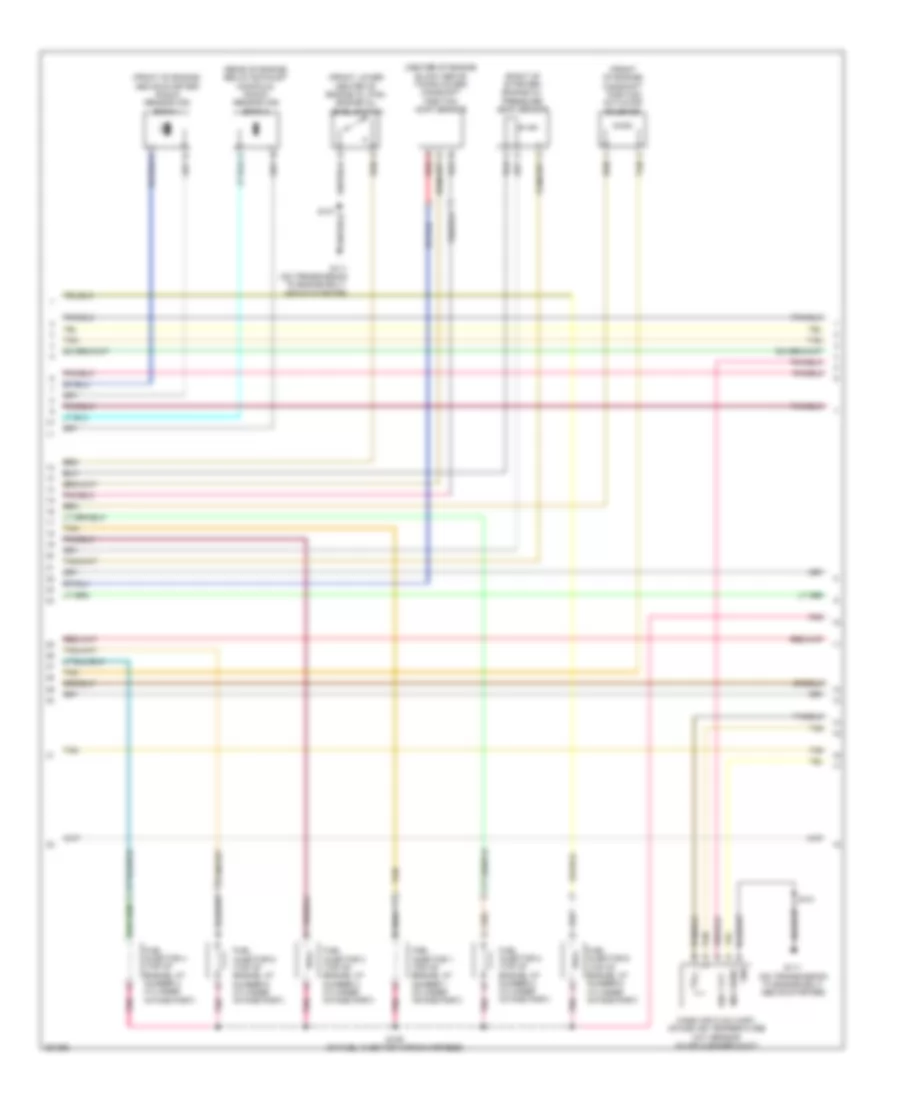
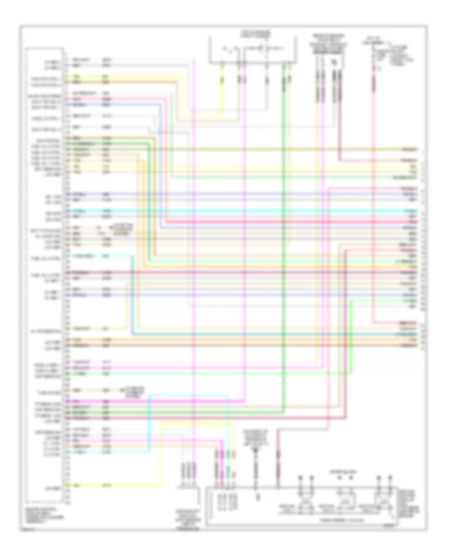
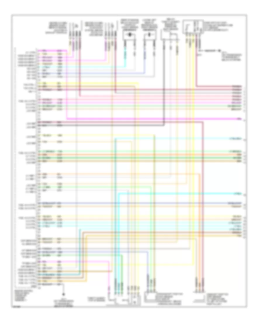
3.5L VIN K, Engine Performance Wiring Diagram (1 of 4) for Chevrolet Impala LT 2007

List of elements for 3.5L VIN K, Engine Performance Wiring Diagram (1 of 4) for Chevrolet Impala LT 2007:
- (on front of automatic transaxle, left of g111) g113
- (rear of engine, mounted in exhaust manifold) heated oxygen sensor (ho2s) 1
- (top of engine) throttle body
- 5v ref
- 5v ref 1
- 5v ref 2
- Air pr sens sig
- Air sol ctrl
- Cam pos sol
- Ckp sens sig
- Cmp sens sig
- Cnstr fuse 10a
- Crankshaft position (ckp) sensor (above transaxle)
- Duty cycle sig
- Ect sens sig
- Engine control module (ecm) (inside air cleaner assembly)
- Evap can purge
- Firing order 1-2-3-4-5-6
- Fuel inj 1 ctrl
- Fuel inj 2 ctrl
- Fuel inj 3 ctrl
- Fuel inj 4 ctrl
- Fuel inj 5 ctrl
- Fuel inj 6 ctrl
- Gnd
- Ho2s hi sen 1
- Ho2s lo ctrl 1
- Ho2s lo sen 1
- Hot at all times
- I/p fuse block (in right front kick panel)
- Ic 1 ctrl
- Ic 2 ctrl
- Ic 3 ctrl
- Ignition coil 1
- Ignition coil 2
- Ignition coil 3
- Ignition control module (icm) (top rear center of engine)
- Ks 1 sig
- Ks 2 sig
- Logic
- Low ref
- Map sens sig
- Nca
- Oil le sw sig
- Oil pr sens sig
- Spark plugs
- Starting/ charging system
- Tac mtr ctrl 1
- Tac mtr ctrl 2
- Tan
- Tp sens 1 sig
- Tp sens 2 sig
- Turn on sig
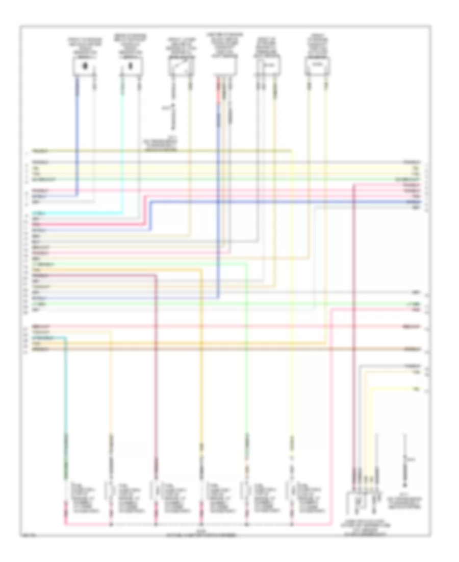
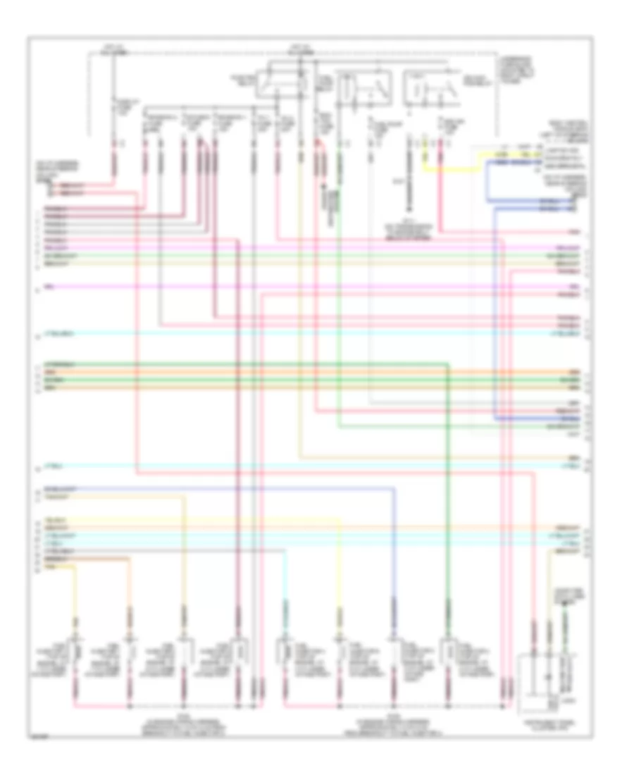
3.5L VIN K, Engine Performance Wiring Diagram (2 of 4) for Chevrolet Impala LT 2007
List of elements for 3.5L VIN K, Engine Performance Wiring Diagram (2 of 4) for Chevrolet Impala LT 2007:
- (center of engine block above timing cover) camshaft position (cmp) sensor
- (front lower center of engine oil pan) engine oil level switch
- (front of engine) camshaft position actuator solenoid
- (front of engine, above starter) knock sensor (ks) bank 1
- (rear of engine, below exhaust manifold) knock sensor (ks) bank 2
- (right of starter) engine oil pressure (eop) sensor
- A red
- Fuel injector 1 (top of engine, at number 1 cylinder intake port)
- Fuel injector 2 (top of engine, at number 2 cylinder intake port)
- Fuel injector 3 (top of engine, at number 3 cylinder intake port)
- Fuel injector 4 (top of engine, at number 4 cylinder intake port)
- Fuel injector 5 (top of engine, at number 5 cylinder intake port)
- Fuel injector 6 (top of engine, at number 6 cylinder intake port)
- G111 (on transmission to engine bolt, above starter)
- Gnd
- Ign 1 vlt
- Maf sens
- Mass air flow (maf)/ intake air temperature (iat) sensor (in air cleaner duct)
- Pnk
- S101
- S109 (on fuel injector wiring harness)
- Tan
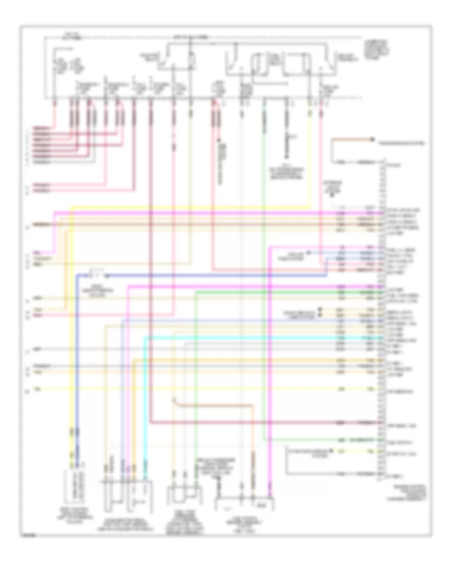
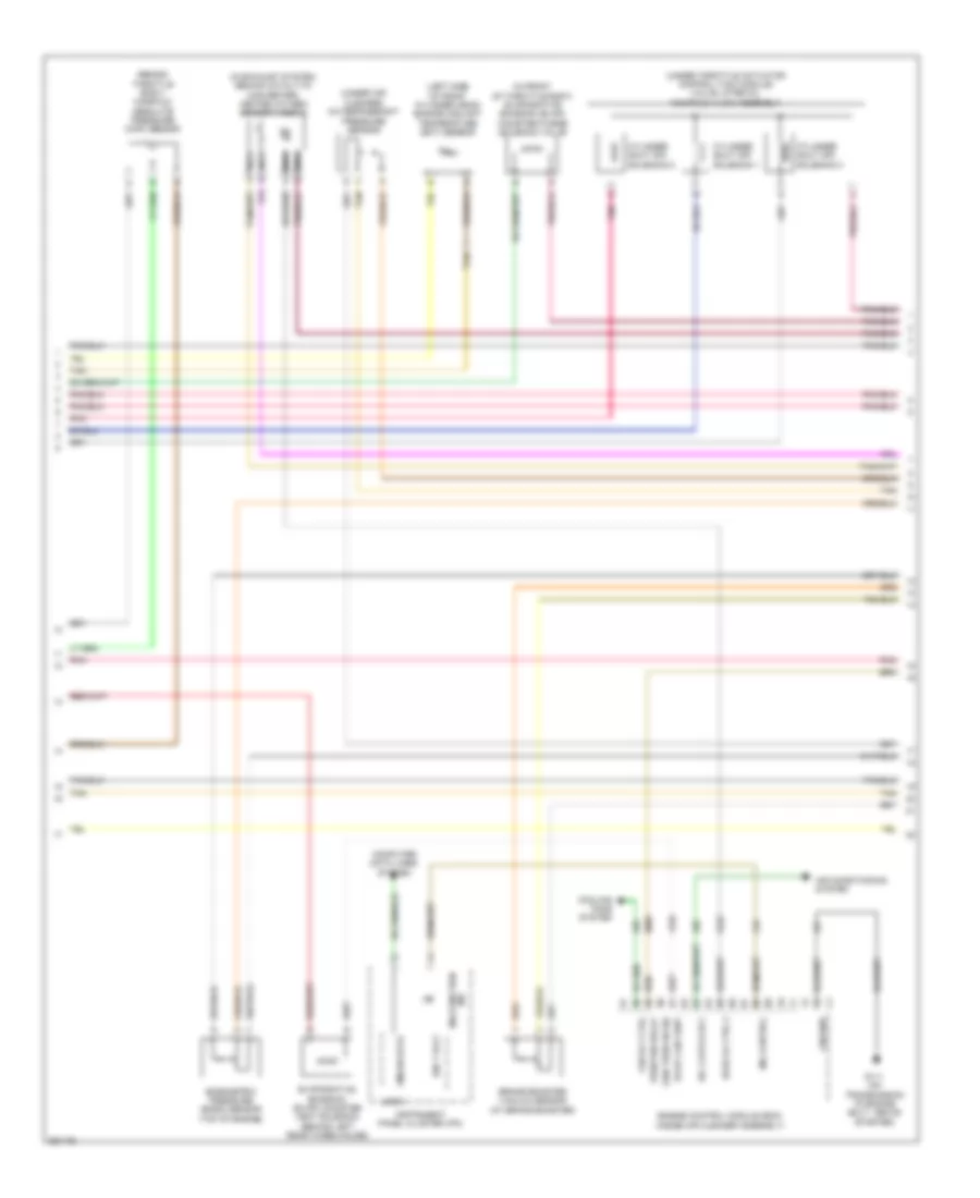
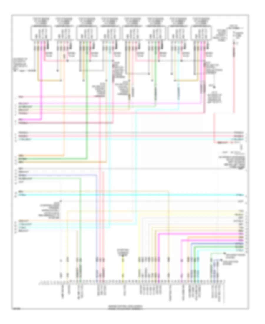
3.5L VIN K, Engine Performance Wiring Diagram (3 of 4) for Chevrolet Impala LT 2007
List of elements for 3.5L VIN K, Engine Performance Wiring Diagram (3 of 4) for Chevrolet Impala LT 2007:
- (behind throttle body) manifold absolute pressure (map) sensor
- (in exhaust system, behind catalytic converter) heated oxygen sensor (ho2s) 2
- (in front of throttle body) evaporative emission (evap) canister purge solenoid valve
- (left side of front cylinder head) engine coolant temperature (ect) sensor
- (on left side of vehicle, near throttle body) (sulev) secondary air injection (air) pump relay
- (on left side of vehicle, near throttle body) (sulev) secondary air injection (air) solenoid relay
- (under air cleaner) a/c refrigerant pressure sensor
- A/c clutch rly
- Air conditioning system
- Computer data lines system
- Cooling fans system
- Engine control module (ecm) (inside air cleaner assembly)
- Evap can vent
- Evaporative emission (evap) canister vent solenoid (behind left rear wheelhouse)
- Fan rly ctrl
- G111 (on transmission to engine bolt, above starter)
- G115 (on transmission case, below brake booster)
- Gen turn on sig
- Gmlan data
- Ground
- Ho2s lo ctrl 2
- Ign 1 volt
- Instrument panel cluster(ipc)
- Logic
- Malfunction ind
- Mil control
- Nca
- Pnk
- Pwr/trn relay
- S101
- Sencondary air injection (air) solenoid (sulev) (near ignition control module)
- Sencondery air injection (air) pump (sulev) (near g111)
- Tan
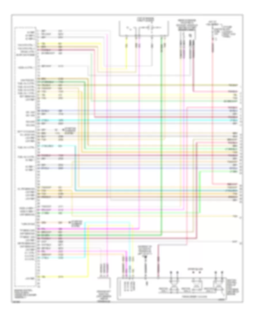
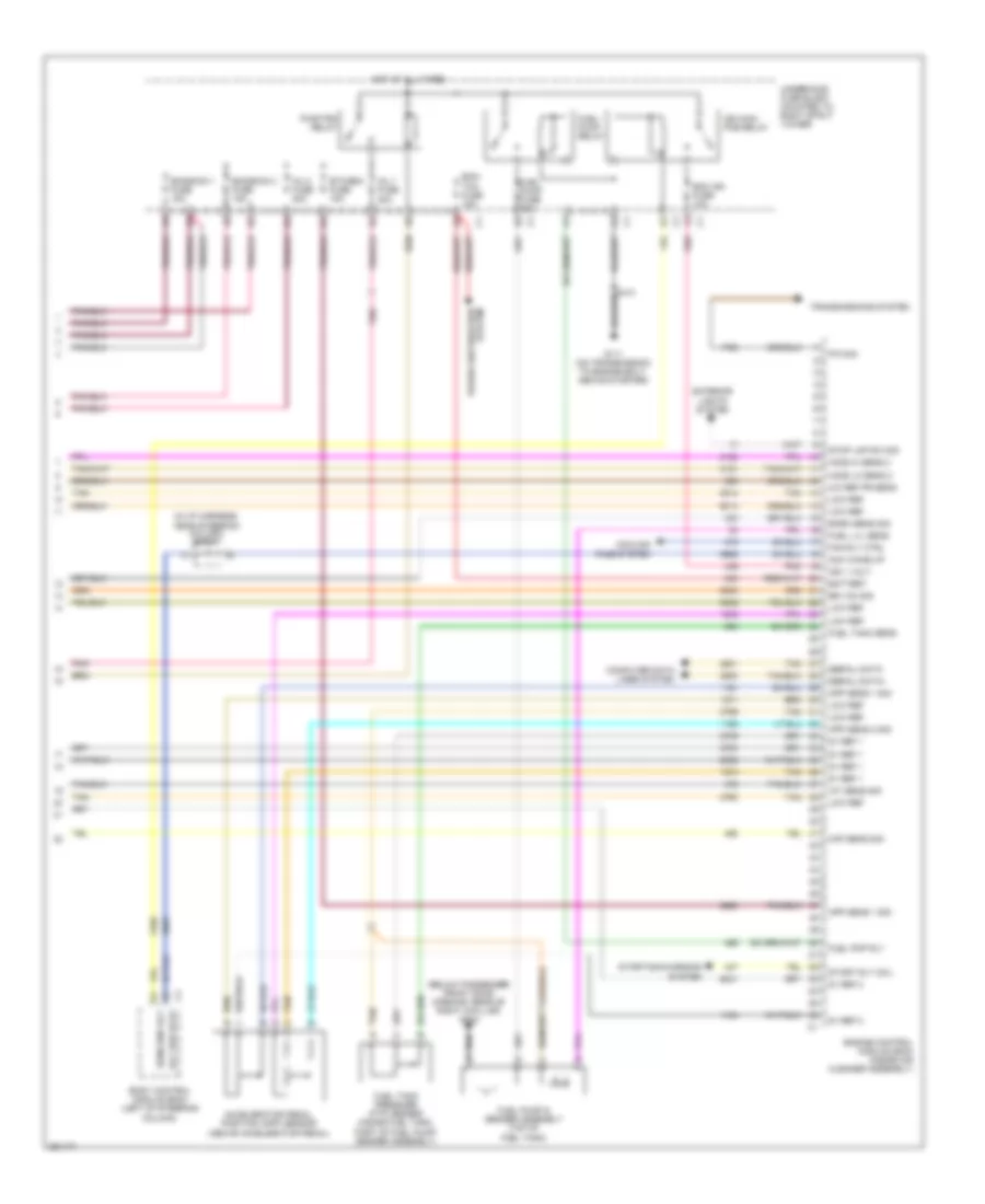
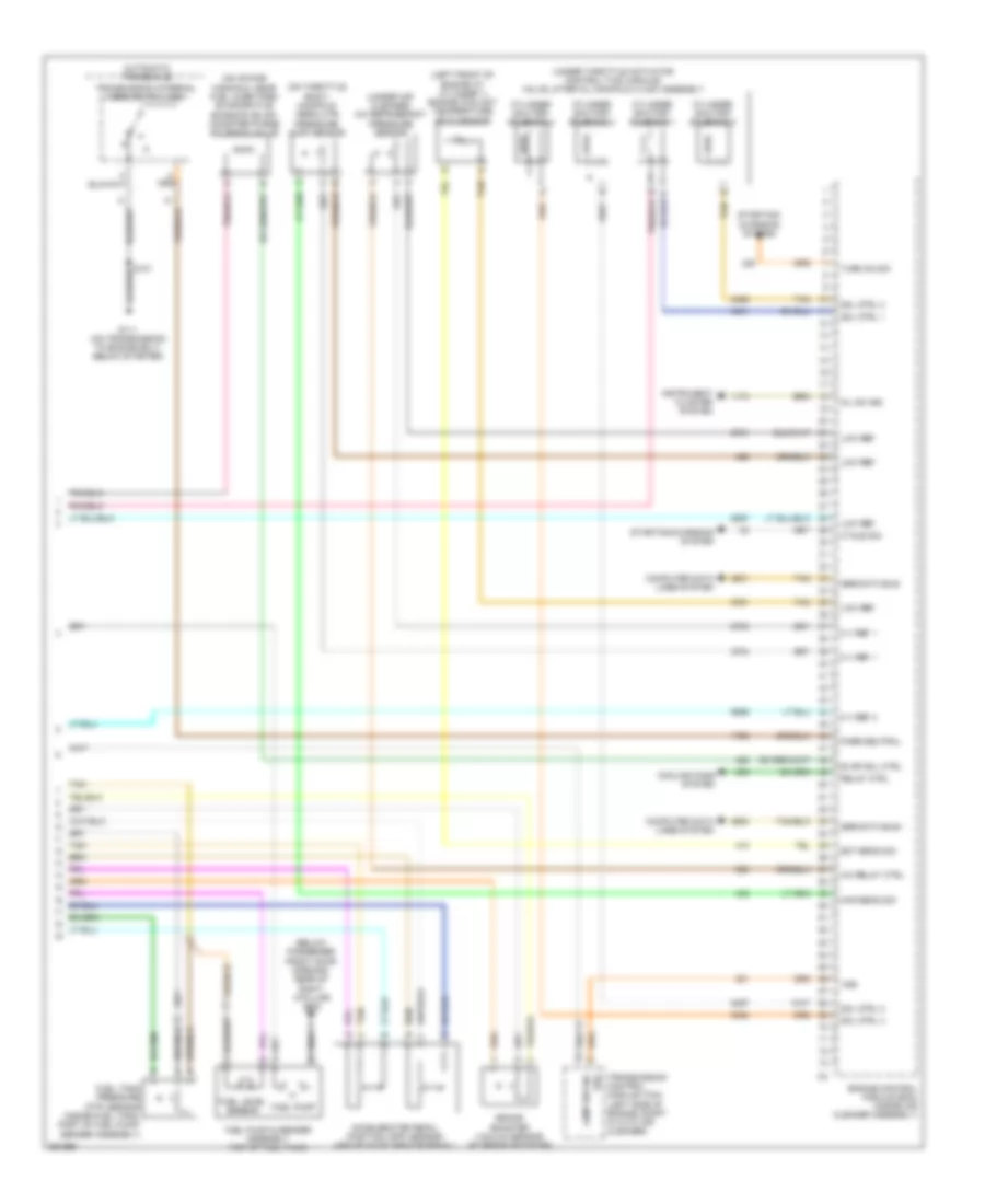
3.5L VIN K, Engine Performance Wiring Diagram (4 of 4) for Chevrolet Impala LT 2007
List of elements for 3.5L VIN K, Engine Performance Wiring Diagram (4 of 4) for Chevrolet Impala LT 2007:
- (below passenger front door opening, rear of right a-pillar) g302
- 5v ref 1
- 5v ref 2
- A/c ref pr sens
- Acc ser data
- Acc wake up
- Accelerator pedal position (app) sensor (above accelerator pedal)
- Air pu rly ctrl
- Air pump fuse 60a
- Air sol fuse 15a
- App sens 1 sig
- App sens 2 sig
- Battery
- Body control module (bcm) (left of steering column)
- Computer data lines system
- Cooling fans system
- Ecm ign fuse 10a
- Ecm/ tcm fuse 15a
- Emission 1 fuse 15a
- Emission 2 fuse 15a
- Engine control module (ecm) (inside air cleaner assembly)
- Etc/ecm fuse 15a
- Exterior lights system
- Fan rly ctrl
- Fuel lvl sens
- Fuel pmp rly
- Fuel pump & sender assembly (top of fuel tank)
- Fuel pump fuse 15a
- Fuel tank pressure (ftp) sensor (inside fuel tank, part of fuel pump/ sender assembly)
- Fuel tank sens
- Fuel/ pump relay
- G111 (on transmission to engine bolt, above starter)
- Ho2s hi sens 2
- Ho2s lo sens 2
- Hot at all times
- Iat sens sig
- Ign 1 volt
- Ign main pcb relay
- Inj 1 fuse 20a
- Inj 2 fuse 20a
- Low ref
- Maf sens sig
- P/n sig
- Pnk
- Power distribution system
- Pwr/trn relay
- Run/crnk rly
- Serial data+
- Serial data-
- Sp207 (near steering column)
- Start rly coil
- Starting/charging system
- Stop lmp sw sig
- Tan
- Transmissions system
- Underhood fuse block (mounted to right strut tower)
3.5L VIN N
3.5L VIN N, Engine Performance Wiring Diagram (1 of 4) for Chevrolet Impala LT 2007
List of elements for 3.5L VIN N, Engine Performance Wiring Diagram (1 of 4) for Chevrolet Impala LT 2007:
- (on front of automatic transaxle, left of g111) g113
- (rear of engine, mounted in exhaust manifold) heated oxygen sensor (ho2s) 1
- (top of engine) throttle body
- 5v ref
- 5v ref 1
- 5v ref 2
- Air pr sens sig
- Air sol ctrl
- Cam pos sol
- Ckp sens sig
- Cmp sens sig
- Cnstr fuse 10a
- Crankshaft position (ckp) sensor (above transaxle)
- Duty cycle sig
- Ect sens sig
- Engine control module (ecm) (inside air cleaner assembly)
- Evap can purge
- Firing order 1-2-3-4-5-6
- Fuel inj 1 ctrl
- Fuel inj 2 ctrl
- Fuel inj 3 ctrl
- Fuel inj 4 ctrl
- Fuel inj 5 ctrl
- Fuel inj 6 ctrl
- Gnd
- Ho2s hi sen 1
- Ho2s lo ctrl 1
- Ho2s lo sen 1
- Hot at all times
- I/p fuse block (in right front kick panel)
- Ic 1 ctrl
- Ic 2 ctrl
- Ic 3 ctrl
- Ignition coil 1
- Ignition coil 2
- Ignition coil 3
- Ignition control module (icm) (top rear center of engine)
- Ks 1 sig
- Ks 2 sig
- Logic
- Low ref
- Map sens sig
- Nca
- Oil le sw sig
- Oil pr sens sig
- Spark plugs
- Starting/ charging system
- Tac mtr ctrl 1
- Tac mtr ctrl 2
- Tan
- Tp sens 1 sig
- Tp sens 2 sig
- Turn on sig
3.5L VIN N, Engine Performance Wiring Diagram (2 of 4) for Chevrolet Impala LT 2007
List of elements for 3.5L VIN N, Engine Performance Wiring Diagram (2 of 4) for Chevrolet Impala LT 2007:
- (center of engine block above timing cover) camshaft position (cmp) sensor
- (front lower center of engine oil pan) engine oil level switch
- (front of engine) camshaft position actuator solenoid
- (front of engine, above starter) knock sensor (ks) bank 1
- (rear of engine, below exhaust manifold) knock sensor (ks) bank 2
- (right of starter) engine oil pressure (eop) sensor
- A red
- Fuel injector 1 (top of engine, at number 1 cylinder intake port)
- Fuel injector 2 (top of engine, at number 2 cylinder intake port)
- Fuel injector 3 (top of engine, at number 3 cylinder intake port)
- Fuel injector 4 (top of engine, at number 4 cylinder intake port)
- Fuel injector 5 (top of engine, at number 5 cylinder intake port)
- Fuel injector 6 (top of engine, at number 6 cylinder intake port)
- G111 (on transmission to engine bolt, above starter)
- Gnd
- Ign 1 vlt
- Maf sens
- Mass air flow (maf)/ intake air temperature (iat) sensor (in air cleaner duct)
- Pnk
- S101
- S109 (on fuel injector wiring harness)
- Tan
3.5L VIN N, Engine Performance Wiring Diagram (3 of 4) for Chevrolet Impala LT 2007
List of elements for 3.5L VIN N, Engine Performance Wiring Diagram (3 of 4) for Chevrolet Impala LT 2007:
- (behind throttle body) manifold absolute pressure (map) sensor
- (in exhaust system, behind catalytic converter) heated oxygen sensor (ho2s) 2
- (in front of throttle body) evaporative emission (evap) canister purge solenoid valve
- (left side of front cylinder head) engine coolant temperature (ect) sensor
- (on left side of vehicle, near throttle body) (sulev) secondary air injection (air) pump relay
- (on left side of vehicle, near throttle body) (sulev) secondary air injection (air) solenoid relay
- (under air cleaner) a/c refrigerant pressure sensor
- A/c clutch rly
- Air conditioning system
- Computer data lines system
- Cooling fans system
- Engine control module (ecm) (inside air cleaner assembly)
- Evap can vent
- Evaporative emission (evap) canister vent solenoid (behind left rear wheelhouse)
- Fan rly ctrl
- G111 (on transmission to engine bolt, above starter)
- G115 (on transmission case, below brake booster)
- Gen turn on sig
- Gmlan data
- Ground
- Ho2s lo ctrl 2
- Ign 1 volt
- Instrument panel cluster(ipc)
- Logic
- Malfunction ind
- Mil control
- Nca
- Pnk
- Pwr/trn relay
- S101
- Sencondary air injection (air) solenoid (sulev) (near ignition control module)
- Sencondery air injection (air) pump (sulev) (near g111)
- Tan
3.5L VIN N, Engine Performance Wiring Diagram (4 of 4) for Chevrolet Impala LT 2007
List of elements for 3.5L VIN N, Engine Performance Wiring Diagram (4 of 4) for Chevrolet Impala LT 2007:
- (below passenger front door opening, rear of right a-pillar) g302
- 5v ref 1
- 5v ref 2
- A/c ref pr sens
- Acc ser data
- Acc wake up
- Accelerator pedal position (app) sensor (above accelerator pedal)
- Air pu rly ctrl
- Air pump fuse 60a
- Air sol fuse 15a
- App sens 1 sig
- App sens 2 sig
- Battery
- Body control module (bcm) (left of steering column)
- Computer data lines system
- Cooling fans system
- Ecm ign fuse 10a
- Ecm/ tcm fuse 15a
- Emission 1 fuse 15a
- Emission 2 fuse 15a
- Engine control module (ecm) (inside air cleaner assembly)
- Etc/ecm fuse 15a
- Exterior lights system
- Fan rly ctrl
- Fuel lvl sens
- Fuel pmp rly
- Fuel pump & sender assembly (top of fuel tank)
- Fuel pump fuse 15a
- Fuel tank pressure (ftp) sensor (inside fuel tank, part of fuel pump/ sender assembly)
- Fuel tank sens
- Fuel/ pump relay
- G111 (on transmission to engine bolt, above starter)
- Ho2s hi sens 2
- Ho2s lo sens 2
- Hot at all times
- Iat sens sig
- Ign 1 volt
- Ign main pcb relay
- Inj 1 fuse 20a
- Inj 2 fuse 20a
- Low ref
- Maf sens sig
- P/n sig
- Pnk
- Power distribution system
- Pwr/trn relay
- Run/crnk rly
- Serial data+
- Serial data-
- Sp207 (near steering column)
- Start rly coil
- Starting/charging system
- Stop lmp sw sig
- Tan
- Transmissions system
- Underhood fuse block (mounted to right strut tower)
3.9L VIN R
3.9L VIN R, Engine Performance Wiring Diagram (1 of 4) for Chevrolet Impala LT 2007
List of elements for 3.9L VIN R, Engine Performance Wiring Diagram (1 of 4) for Chevrolet Impala LT 2007:
- (on front of automatic transaxle, left of g111) g113
- (rear of engine, mounted in exhaust manifold) heated oxygen sensor (ho2s) 1
- (top of engine) throttle body
- 5v ref 1
- 5v ref 2
- Cam pos sol
- Ckp sens sig
- Cmp sens sig
- Cnstr fuse 10a
- Crankshaft position (ckp) sensor (above transaxle)
- Duty cycle sig
- Ect sens sig
- Engine control module (ecm) (inside air cleaner assembly)
- Evap can purge
- Firing order 1-2-3-4-5-6
- Fuel inj 1 ctrl
- Fuel inj 2 ctrl
- Fuel inj 3 ctrl
- Fuel inj 4 ctrl
- Fuel inj 5 ctrl
- Fuel inj 6 ctrl
- Gnd
- Ho2s hi sen 1
- Ho2s lo ctrl 1
- Ho2s lo sen 1
- Hot at all times
- I/p fuse block (in right front kick panel)
- Ic 1 ctrl
- Ic 2 ctrl
- Ic 3 ctrl
- Ignition coil 1
- Ignition coil 2
- Ignition coil 3
- Ignition control module (icm) (top rear center of engine)
- Ks 1 sig
- Ks 2 sig
- Logic
- Low ref
- Map sens sig
- Nca
- Oil le sw sig
- Oil pr sens sig
- Pnk
- Shut off sol 1
- Shut off sol 3
- Shut off sol 5
- Spark plugs
- Starting/ charging system
- Tac mtr ctrl 1
- Tac mtr ctrl 2
- Tan
- Tp sens 1 sig
- Tp sens 2 sig
- Turn on sig
3.9L VIN R, Engine Performance Wiring Diagram (2 of 4) for Chevrolet Impala LT 2007
List of elements for 3.9L VIN R, Engine Performance Wiring Diagram (2 of 4) for Chevrolet Impala LT 2007:
- (center of engine block above timing cover) camshaft position (cmp) sensor
- (front lower center of engine oil pan) engine oil level switch
- (front of engine) camshaft position actuator solenoid
- (front of engine, above starter) knock sensor (ks) bank 1
- (rear of engine, below exhaust manifold) knock sensor (ks) bank 2
- (right of starter) engine oil pressure (eop) sensor
- A red
- Fuel injector 1 (top of engine, at number 1 cylinder intake port)
- Fuel injector 2 (top of engine, at number 2 cylinder intake port)
- Fuel injector 3 (top of engine, at number 3 cylinder intake port)
- Fuel injector 4 (top of engine, at number 4 cylinder intake port)
- Fuel injector 5 (top of engine, at number 5 cylinder intake port)
- Fuel injector 6 (top of engine, at number 6 cylinder intake port)
- G111 (on transmission to engine bolt, above starter)
- Gnd
- Ign 1 vlt
- Maf sens
- Mass air flow (maf)/ intake air temperature (iat) sensor (in air cleaner duct)
- Pnk
- S101
- S109 (on fuel injector wiring harness)
- Tan
3.9L VIN R, Engine Performance Wiring Diagram (3 of 4) for Chevrolet Impala LT 2007
List of elements for 3.9L VIN R, Engine Performance Wiring Diagram (3 of 4) for Chevrolet Impala LT 2007:
- (behind throttle body) manifold absolute pressure (map) sensor
- (in exhaust system, behind catalytic converter) heated oxygen sensor (ho2s) 2
- (in front of throttle body) evaporative emission (evap) canister purge solenoid valve
- (left side of front cylinder head) engine coolant temperature (ect) sensor
- (under air cleaner) a/c refrigerant pressure sensor
- (under throttle actuator control (tac) module) valve lifter oil manifold (vlom) assembly
- A/c clutch rly
- Air conditioning system
- Barometric pressure (baro) sensor (top of engine)
- Brake booster vacuum sensor (at brake booster)
- Computer data lines system
- Cooling fans system
- Cylinder shut off solenoid 1
- Cylinder shut off solenoid 3
- Cylinder shut off solenoid 5
- Engine control module (ecm) (inside air cleaner assembly)
- Evap can vent
- Evaporative emission (evap) canister vent solenoid (behind left rear wheelhouse)
- Fan rly ctrl
- G111 (on transmission to engine bolt, above starter)
- Gen turn on sig
- Gmlan data
- Ground
- Ho2s lo ctrl 2
- Ign 1 volt
- Instrument panel cluster (ipc)
- Logic
- Malfunction ind
- Mil control
- Nca
- Pnk
- Pwr/trn relay
- Tan
3.9L VIN R, Engine Performance Wiring Diagram (4 of 4) for Chevrolet Impala LT 2007
List of elements for 3.9L VIN R, Engine Performance Wiring Diagram (4 of 4) for Chevrolet Impala LT 2007:
- (below passenger front door opening, rear of right a-pillar) g302
- (in i/p harness,
- 5v ref 1
- 5v ref 2
- A/c ref pr sens
- Acc ser data
- Acc wake up
- Accelerator pedal position (app) sensor (above accelerator pedal)
- App sens 1 sig
- App sens 2 sig
- Baro sens sig
- Battery
- Body control module (bcm) (left of steering column)
- Br vac sig
- Computer data lines system
- Cooling fans system
- Ecm ign fuse 10a
- Ecm/ tcm fuse 15a
- Emission 1 fuse 15a
- Emission 2 fuse 15a
- Engine control module (ecm) (inside air cleaner assembly)
- Etc/ecm fuse 15a
- Exterior lights system
- Fan rly ctrl
- Fuel lvl sens
- Fuel pmp rly
- Fuel pump & sender assembly (top of fuel tank)
- Fuel pump fuse 15a
- Fuel tank pressure (ftp) sensor (inside fuel tank, part of fuel pump/ sender assembly)
- Fuel tank sens
- Fuel/ pump relay
- G111 (on transmission to engine bolt, above starter)
- Ho2s hi sens 2
- Ho2s lo sens 2
- Hot at all times
- Iat sens sig
- Ign 1 volt
- Ign main pcb relay
- Inj 1 fuse 20a
- Inj 2 fuse 20a
- Low ref
- Maf sens sig
- Near steering column) sp207
- P/n sig
- Pnk
- Power distribution system
- Pwr/trn relay
- Run/crnk rly
- Serial data+
- Serial data-
- Start rly coil
- Starting/charging system
- Stop lmp sw sig
- Tan
- Transmissions system
- Underhood fuse block (mounted to right strut tower)
5.3L VIN C
5.3L VIN C, Engine Performance Wiring Diagram (1 of 4) for Chevrolet Impala LT 2007
List of elements for 5.3L VIN C, Engine Performance Wiring Diagram (1 of 4) for Chevrolet Impala LT 2007:
- (below throttle body) engine oil pressure (eop) sensor
- (lower left rear of engine block) knock sensor (ks) bank 1
- (rear of engine, below exhaust manifold) knock sensor (ks) bank 2
- 5 v ref 1
- 5 v ref 2
- A tan
- Camshaft position (cmp) sensor (in timing cover, to left of water pump pulley)
- Ckp sens sig
- Cmp sens sig
- Crankshaft position (ckp) sensor (at end of crankshaft, behind harmonic balancer)
- Engine control module (ecm) (inside air cleaner assembly)
- Fuel inj 1 ctrl
- Fuel inj 2 ctrl
- Fuel inj 3 ctrl
- Fuel inj 4 ctrl
- Fuel inj 5 ctrl
- Fuel inj 6 ctrl
- Fuel inj 7 ctrl
- Fuel inj 8 ctrl
- G111 (on transmission to engine bolt, below starter)
- Gnd
- Heated oxygen sensor (ho2s) 1 (rear of engine, mounted in exhaust manifold)
- Heated oxygen sensor (ho2s) 2 (in exhaust system, behind catalytic converter)
- Ho2s sig sens 1
- Ho2s sig sens 2
- Iat sens sig
- Ic 1 ctrl
- Ic 2 ctrl
- Ic 3 ctrl
- Ic 4 ctrl
- Ic 5 ctrl
- Ic 6 ctrl
- Ic 7 ctrl
- Ic 8 ctrl
- Ign 1 v
- Ign 1 vlt
- Ks 1 sig
- Ks 2 sig
- Low ref
- Maf sens
- Maf sens sig
- Mass air flow (maf)/ intake air temperature (iat) sensor (in air cleaner duct)
- Nca
- Oil sens sig
- S101
- Tac ctrl 1
- Tac ctrl 2
- Tan
- Throttle body (top of engine)
- Tp sen 1 sig
- Tp sen 2 sig
5.3L VIN C, Engine Performance Wiring Diagram (2 of 4) for Chevrolet Impala LT 2007
List of elements for 5.3L VIN C, Engine Performance Wiring Diagram (2 of 4) for Chevrolet Impala LT 2007:
- (on i/p harness, near steering column) sp206
- (on i/p harness, near steering column) sp207
- Body control module (bcm) (left of steering column)
- Computer data lines system
- Display fuse 10a
- Ecm ign fuse 10a
- Ecm/ tcm fuse 15a
- Emission 1 fuse 15a
- Emission 2 fuse 15a
- Etc/ecm fuse 15a
- Fuel injector 1 (top of engine, at 1 cylinder intake port)
- Fuel injector 2 (top of engine, at 2 cylinder intake port)
- Fuel injector 3 (top of engine, at 3 cylinder intake port)
- Fuel injector 4 (top of engine, at 4 cylinder intake port)
- Fuel injector 5 (top of engine, at 5 cylinder intake port)
- Fuel injector 6 (top of engine, at 6 cylinder intake port)
- Fuel injector 7 (top of engine, at 7 cylinder intake port)
- Fuel injector 8 (top of engine, at 8 cylinder intake port)
- Fuel/ pump relay
- Fuel/pump fuse 15a
- G111 (on transmission to engine bolt, below starter)
- Hot at all times
- Ign main pcb relay
- Ind malfunction logic
- Inj 1 fuse 20a
- Inj 2 fuse 20a
- Instrument panel cluster (ipc)
- Lamp sw sig run/crnk rly acc ser data c4
- Pnk
- Power distribution system
- Pwr/trn relay
- S108 (in engine wiring harness, approximately 5 cm (2 in) from breakout to fuel injector 3)
- S109 (in engine wiring harness, approximately 5 cm (2 in) from breakout to fuel injector 4)
- Ser data
- Tan
- Underhood fuse block (mounted to right strut tower)
- Volt ign 1
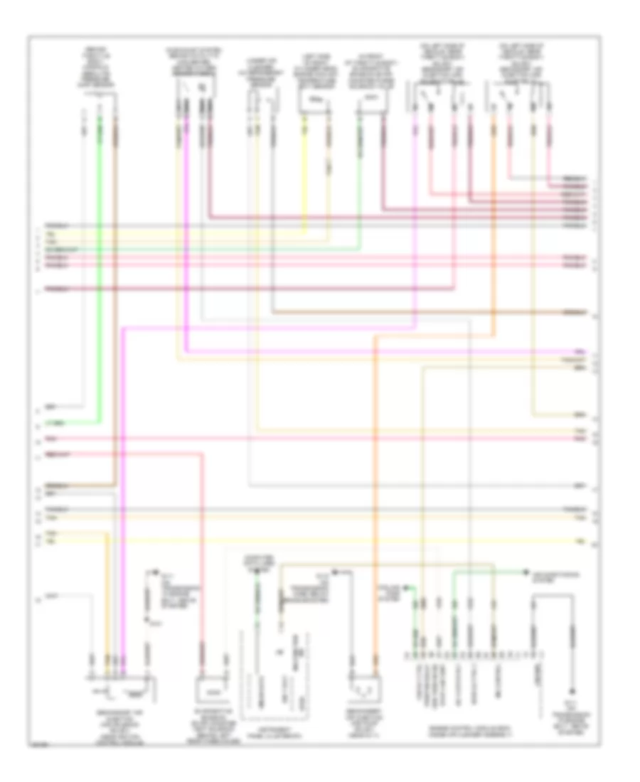
5.3L VIN C, Engine Performance Wiring Diagram (3 of 4) for Chevrolet Impala LT 2007
List of elements for 5.3L VIN C, Engine Performance Wiring Diagram (3 of 4) for Chevrolet Impala LT 2007:
- (in engine wiring harness, approximately
- (on front of automatic transaxle, left of g111) g113
- (top of engine, at number 1 cylinder) ignition coil 1
- (top of engine, at number 2 cylinder) ignition coil 2
- (top of engine, at number 3 cylinder) ignition coil 3
- (top of engine, at number 4 cylinder) ignition coil 4
- (top of engine, at number 5 cylinder) ignition coil 5
- (top of engine, at number 6 cylinder) ignition coil 6
- (top of engine, at number 7 cylinder) ignition coil 7
- (top of engine, at number 8 cylinder) ignition coil 8
- 5 v ref 1
- 5 v ref 2
- 5.5 cm (2.25 in) from breakout to starter)
- Air conditioning system
- App sens 1
- App sens 2
- Battery
- Cnstr fuse 10a
- Coil ctrl
- Cooling fans system
- Engine control module (ecm) (inside air cleaner assembly)
- Evap sol ctrl
- Fuel sens sig
- G113 (on front of automatic transaxle, left of g111)
- Gnd
- Harness)
- Hot at all times
- I/p fuse block (in right front kick panel)
- Ic 1 ctrl
- Ic 2 ctrl
- Ic 3 ctrl
- Ic 4 ctrl
- Ic 5 ctrl
- Ic 6 ctrl
- Ic 7 ctrl
- Ic 8 ctrl
- Ign 1 vlt
- Lamp sw sig
- Low ref
- Mil lmp ctrl
- Nca
- Pnk
- Pwr/trn ctrl
- Red
- Relay ctrl
- S105
- S107 pnk (on ignition control module wiring harness)
- S130
- S132 (on ignition control module wiring harness)
- Ser data
- Spark plug
- Starting/ charging system
- Tan
- Vacuum sig
5.3L VIN C, Engine Performance Wiring Diagram (4 of 4) for Chevrolet Impala LT 2007
List of elements for 5.3L VIN C, Engine Performance Wiring Diagram (4 of 4) for Chevrolet Impala LT 2007:
- (below passenger front door opening, rear of right a-pillar) g302
- (left front of engine at cylinder 1) engine coolant temperature (ect) sensor
- (on intake manifold, near fuel injectors) evaporative emission (evap) canister purge solenoid valve
- (on throttle body) manifold absolute pressure (map) sensor
- (under air cleaner) a/c refrigerant pressure sensor
- (under throttle actuator control (tac) module) valve lifter oil manifold (vlom) assembly
- 5 v ref 1
- 5 v ref 2
- A/c relay ctrl
- Accelerator pedal position (app) sensor (above accelerator pedal)
- Automatic transaxle
- B tan
- Brake booster vacuum sensor (at brake booster)
- Computer data lines system
- Cooling fans system
- Cycle sig
- Cylinder shutoff solenoid 1
- Cylinder shutoff solenoid 2
- Cylinder shutoff solenoid 3
- Cylinder shutoff solenoid 4
- Ect sens sig
- Engine control module (ecm) (inside air cleaner assembly)
- Evap sol ctrl
- Fuel level sensor
- Fuel pump
- Fuel pump & sender assembly (top of fuel tank)
- Fuel tank pressure (ftp) sensor (inside fuel tank, part of fuel pump/ sender assembly)
- G111 (on transmission to engine bolt, below starter)
- Instrument cluster system
- Lamp sw sig
- Low ref
- Map sens sig
- Oil sw sig
- Park/neutral
- Relay ctrl
- Ser data bus+
- Ser data bus-
- Sol ctrl 1
- Sol ctrl 2
- Sol ctrl 3
- Sol ctrl 4
- Starting/ charging system
- Starting/charging system
- Tan
- Transmission control module (tcm) (left side of engine compt in with air cleaner)
- Transmission internal mode switch (ims)
- Turn on sig
- Vss