ENGINE PERFORMANCE
3.1L
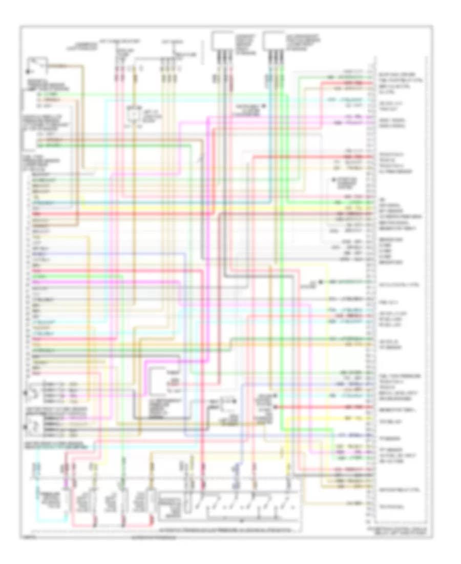
3.1L VIN J, Engine Performance Wiring Diagrams (1 of 3) for Chevrolet Malibu 2000

List of elements for 3.1L VIN J, Engine Performance Wiring Diagrams (1 of 3) for Chevrolet Malibu 2000:
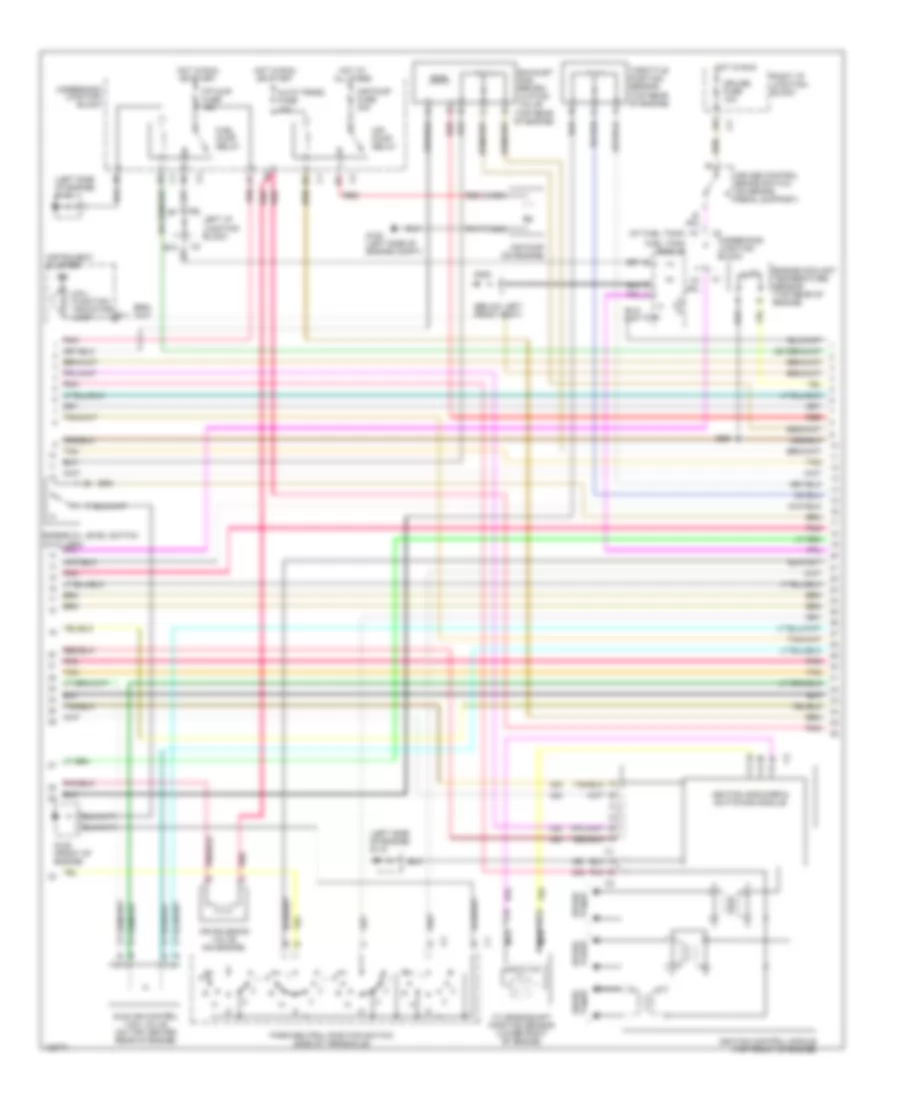
3.1L VIN J, Engine Performance Wiring Diagrams (2 of 3) for Chevrolet Malibu 2000
List of elements for 3.1L VIN J, Engine Performance Wiring Diagrams (2 of 3) for Chevrolet Malibu 2000:
3.1L VIN J, Engine Performance Wiring Diagrams (3 of 3) for Chevrolet Malibu 2000
List of elements for 3.1L VIN J, Engine Performance Wiring Diagrams (3 of 3) for Chevrolet Malibu 2000: