ENGINE PERFORMANCE
2.0L VIN X
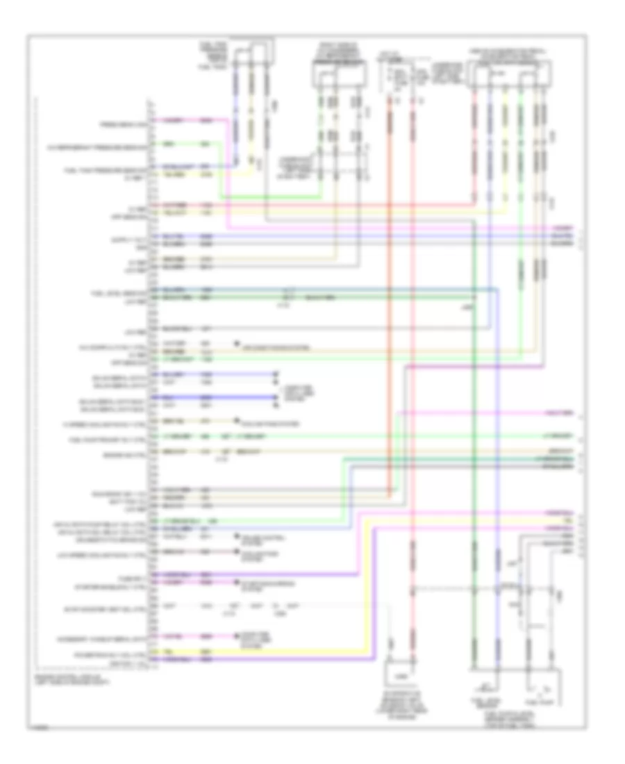
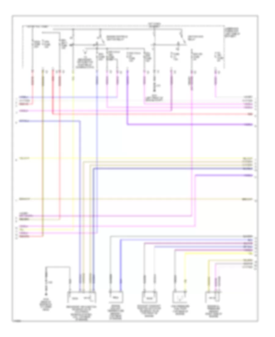
2.0L VIN X, Engine Performance Wiring Diagram (1 of 6) for Chevrolet Malibu LT 2013

List of elements for 2.0L VIN X, Engine Performance Wiring Diagram (1 of 6) for Chevrolet Malibu LT 2013:
- (or 3200)
- (or 3201)
- 2.0l vin x
- 2.5l vin a
- 5-v ref
- 5v ref
- A/c compressor clutch rly ctrl
- A/c press sens 5v ref
- A/c refrigerant press sens lo ref
- A/c refrigerant pressure sens sig
- A/c refrigerant pressure sensor (right side of a/c condenser)
- Accessory wakeup serial data
- Air conditioning system
- Air pressure sig
- App lo ref
- App low ref
- App sens sig (1)
- App sens sig (2)
- Batt pos vol
- Brk pos sen sig
- Brk pos sens 5v ref
- Brk pos sens low ref
- Check engine ind ctrl
- Computer data lines system
- Coolant temp sens sig (2)
- Cooling fans system
- Cruise control system
- Cruise\etc\tcc brk sig
- Engine control module (ecm) (left side of engine compt)
- Engine coolant temperature sensor 2 (lower right side of radiator)
- Evap conister vent sol ctrl
- Evaporative emission vent solenoid valve (right side of fuel tank)
- Exterior lights system
- Fuel level sens lo ref
- Fuel level sens sig
- Fuel line press sens 5v ref
- Fuel line pressure sens lo ref
- Fuel line pressure sens sig
- Fuel pressure sensor (right side of fuel tank)
- Fuel pump controller data out sig
- Fuel tank pressure sens sig
- Fuel tank pressure sensor (top of fuel tank)
- Hi spd cooling fan rly ctrl
- Hi spd gmlan serial data (+)
- Hi spd gmlan serial data (-)
- Low ref
- Low speed cooling fan rly ctrl
- Main relay fused sply
- Powertrain main rly fused sply (1)
- Powertrain rly coil ctrl
- Pre-throttle air press temp sig
- Reaction pump rly coil ctrl
- Reaction solenoid rly coil ctrl
- Run/crank ign 1 vol
- Sens 2 low ref
- Starter enable rly ctrl
- Starting/charging system
- Throttle inlet absolute pressure sensor (2.0l vin x) (on throttle inlet tube near ecm)
- Underhood fuse block (left side of battery) x3
- X115
- X117
- X350
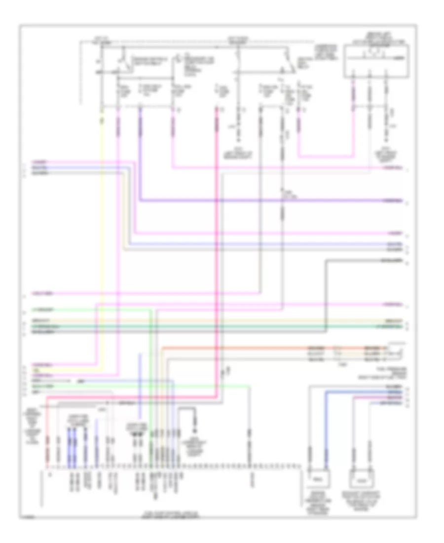
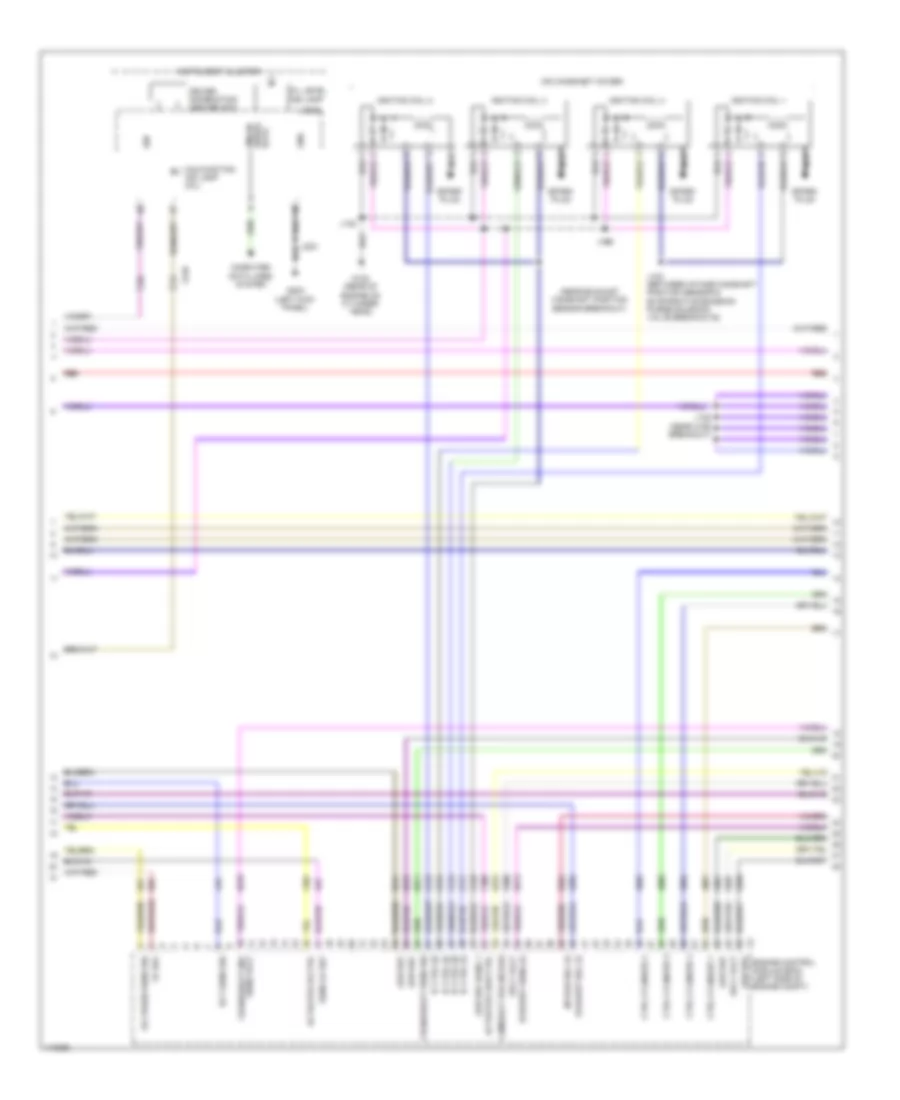
2.0L VIN X, Engine Performance Wiring Diagram (2 of 6) for Chevrolet Malibu LT 2013
List of elements for 2.0L VIN X, Engine Performance Wiring Diagram (2 of 6) for Chevrolet Malibu LT 2013:
- (above accelerator pedal) accelerator pedal position sensor
- 2.0l vin x
- 2.5l vin a
- Batt pos volt
- Cabin htr cool pmp fuse 15a
- Computer data lines system
- From engine controls ignition relay (diagram 3 of 6)
- Fuel level sensor
- Fuel pump
- Fuel pump & level sensor assembly (top of fuel tank)
- Fuel pump driver control module (right side of luggage compt)
- G122 (rear of engine on cylinder head)
- G405 (upper right rear of luggage compt)
- Gmlan ser data (+)
- Gmlan ser data (-)
- Gnd
- Hot at all times
- Ignition 1 volt
- J120
- J406 (w/ vri)
- J434 (body harness, in branch to x420)
- J435
- J436
- Low ref
- Nca
- Out sig
- Sec air pump fuse 50a
- Secondary air injection pump (2.5l: right side of engine)
- Secondary air injection pump relay (california emission system)
- Secondary air injection solenoid valve relay (california emission system)
- Shield extension
- Sply volt
- Underhood fuse block (left side of battery)
- Wakeup serial data
- X115
- X210
- X350
2.0L VIN X, Engine Performance Wiring Diagram (3 of 6) for Chevrolet Malibu LT 2013
List of elements for 2.0L VIN X, Engine Performance Wiring Diagram (3 of 6) for Chevrolet Malibu LT 2013:
- Coil odd fuse 15a
- Cps fuse 10a
- Ecm batt fuse 15a
- Ecm fuse 20a
- Ecm ign fuse 5a
- Engine controls ignition relay
- Engine coolant temperature sensor 1 (top rear of engine)
- Engine oil pressure sensor (right side of engine)
- Exhaust camshaft position actuator solenoid valve (top front of engine)
- Fscm fuse 20a
- Fuse 7.5a
- G101 (left front of engine compt)
- G122 (rear of engine on cylinder head)
- High pressure fuel pump (top rear of engine)
- Hot at all times
- Hot in run or start
- Ignition main relay
- J120
- Mil ign fuse 5a
- Non walk o2 fuse 10a
- Non walk veh fuse 10a
- Red
- Secondary air injection solenoid valve (california emission system) (2.5l: top rear of engine)
- To secondary air injection pump relay (diagram 2 of 6)
- Underhood fuse block (left side of battery)
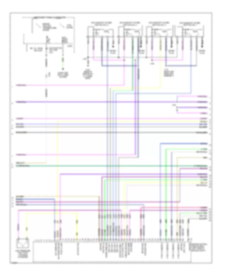
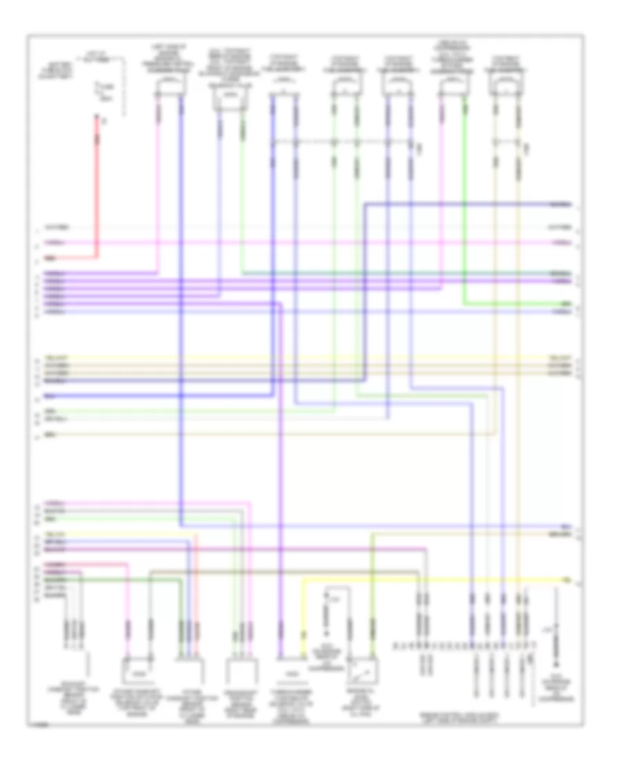
2.0L VIN X, Engine Performance Wiring Diagram (4 of 6) for Chevrolet Malibu LT 2013
List of elements for 2.0L VIN X, Engine Performance Wiring Diagram (4 of 6) for Chevrolet Malibu LT 2013:
- (near exhaust camshaft position sensor breakout)
- (on camshaft cover)
- 5v ref
- Actuator hi ctrl
- Actuator low ctrl
- Camshaft pos intake
- Computer data lines system
- Crankshaft 60x sens volt
- Crankshaft sens sig
- Ctrl cylinder 1
- Ctrl cylinder 2
- Ctrl cylinder 3
- Ctrl cylinder 4
- Data
- Driver information center (dic)
- Ect sens sig
- Engine control module (ecm) (left side of engine compt)
- Exhaust sens (1)
- Exhaust sol (1)
- G122 (rear of engine on cylinder head)
- G203 (left kick panel)
- Gnd
- Ic ctrl (1)
- Ic ctrl (2)
- Ic ctrl (3)
- Ic ctrl (4)
- Ign
- Ignition coil 1
- Ignition coil 2
- Ignition coil 3
- Ignition coil 4
- Instrument cluster
- Intake sol (1)
- J103 (between intake camshaft position sensor & evaporative emission purge solenoid valve breakouts)
- J106
- J108 (near x160 breakout)
- J122
- J203
- Logic
- Low ref
- Low ref bank 1
- Malfunction ind lamp (mil)
- Nca
- Oil level ind lamp
- Oil press sens sig
- Red
- Sens lo ref
- Serial gmlan
- Spark plug
- Sply volt
- X210
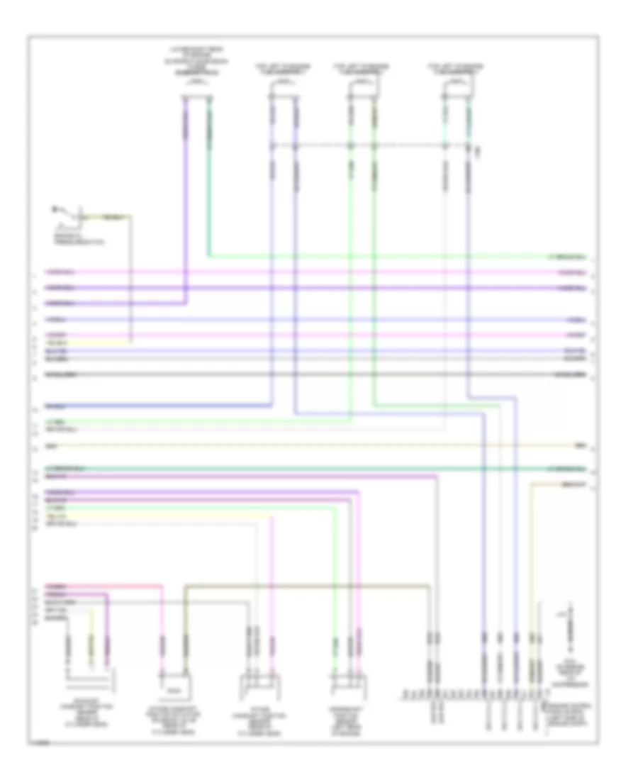
2.0L VIN X, Engine Performance Wiring Diagram (5 of 6) for Chevrolet Malibu LT 2013
List of elements for 2.0L VIN X, Engine Performance Wiring Diagram (5 of 6) for Chevrolet Malibu LT 2013:
- (2.0l: top right rear of engine) (2.5l: top right front of engine) evaporative emission purge solenoid valve
- (above a/c compressor) (2.0l vin x) turbocharger bypass solenoid valve
- (left side of engine) engine oil pressure control solenoid valve
- (top right of engine)
- (top right of engine) fuel injector 2
- (top right of engine) fuel injector 3
- (top right of engine) fuel injector 4
- Battery fuse block (on battery)
- Crankshaft position sensor (right rear of engine)
- Engine control module (ecm) (left side of engine compt)
- Engine oil level switch (right side of oil pan)
- Exhaust camshaft position sensor (front of cylinder head)
- Fuel injector 1
- Fuse 250a
- G121 (on engine rear of a/c compressor)
- Gnd
- Hot at all times
- Intake camshaft position actuator solenoid valve (top front of engine)
- Intake camshaft position sensor (front of cylinder head)
- J121
- Low ref
- Red
- Sply cylinder 1
- Sply cylinder 2
- Sply cylinder 3
- Sply cylinder 4
- Turbocharger wastegate solenoid valve (2.0l vin x) (above a/c compressor)
- X160
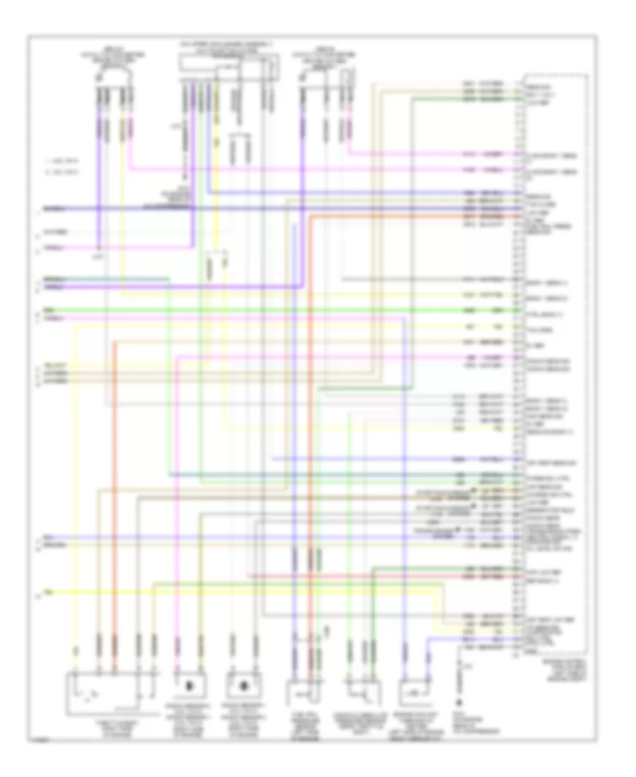
2.0L VIN X, Engine Performance Wiring Diagram (6 of 6) for Chevrolet Malibu LT 2013
List of elements for 2.0L VIN X, Engine Performance Wiring Diagram (6 of 6) for Chevrolet Malibu LT 2013:
- (above catalytic converter) heated oxygen sensor 1
- (below catalytic converter) heated oxygen sensor 2
- (on upper air cleaner assembly) multifunction intake air sensor
- 2.0l vin x
- 2.5l vin a
- 5v ref
- 5v ref fuel rail press sens sig
- Air temp low ref
- Air temp sens sig
- Bank 1 sens (1)
- Bank 1 sens (2)
- Charge ind ctrl
- Ctrl bank (1)
- Engine control module (ecm) (left side of engine compt)
- Engine coolant thermostat heater (left side of engine near thermostat)
- Fuel rail pressure sensor (left side of engine)
- G121 (on engine rear of a/c compressor)
- Generator field
- Gnd
- Hi sig bank 1 sens (1)
- Hi sig bank 1 sens (2)
- J107
- J121
- Knock sens
- Knock sens sig
- Knock sens transmission park/ neutral signal (1) command sig
- Knock sensor 1 (2.0l vin x) knock sensor 2 (2.5l vin a) (right side of engine)
- Knock sensor 2 (2.0l vin x) knock sensor 1 (2.5l vin a) (right side of engine)
- Low ref
- Maf sens sig
- Manifold absolute pressure sensor (near throttle body)
- Map low ref
- Map sens sig
- Nca
- Oil level sw sig
- Purge sol ctrl
- Ref bank (1)
- Sens sig
- Sens sig bank (1)
- Sply volt
- Starting/charging system
- Tac close
- Tac open
- Throttle body (right side of engine)
- Tp sens sig waste gate sol ctrl cool ctrl
- Transmissions system
- X160
2.4L VIN R
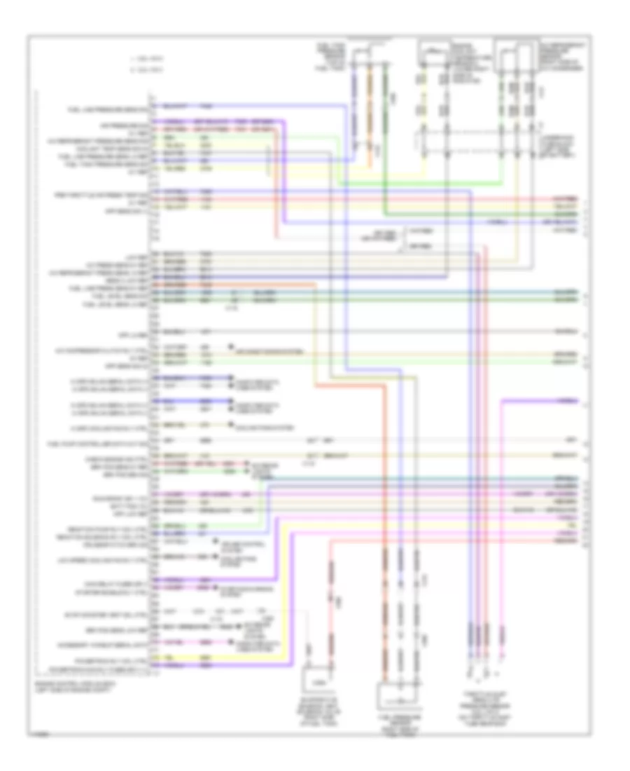
2.4L VIN R, Engine Controls Wiring Diagram (1 of 6) for Chevrolet Malibu LT 2013
List of elements for 2.4L VIN R, Engine Controls Wiring Diagram (1 of 6) for Chevrolet Malibu LT 2013:
- (above accelerator pedal) accelerator pedal position (app) sensor
- (right side of a/c condenser) a/c refrigerant pressure sensor
- 5v ref
- 5v ref 1
- A/c compr clth rly ctrl
- A/c refrigerant pressure sens sig
- Accessory wakeup serial data
- Air conditioning system
- Air inj rctn pump relay coil ctrl
- Air inj rctn sol relay coil ctrl
- App sens sig
- Batt pos vol
- Computer data lines system
- Cooling fans system
- Cps fuse 10a
- Cruise control system
- Cruise/etc/tcc brake sig
- Ecm batt fuse 5a
- Engine control module (left side of engine compt)
- Engine ind ctrl
- Evap conister vent sol ctrl
- Evaporative emission vent solenoid valve (lower right rear of engine)
- Fuel level sens sig
- Fuel level sensor
- Fuel pump
- Fuel pump & level sender assembly (top of fuel tank)
- Fuel pump primary rly ctrl
- Fuel tank pressure sens sig
- Fuel tank pressure sensor (top of fuel tank)
- Fuse sply
- Gmlan serial data bus +
- Gmlan serial data bus -
- Gmlan serial data+
- Gmlan serial data-
- Gnd
- Hi speed cooling fan rly ctrl
- Hot at all times
- Ignition 1 vol
- J395
- J457
- Low ref
- Low speed cooling fan rly ctrl
- Nca
- Powertrain rly coil ctrl
- Press sens 2 sig
- Run/crank ign 1 vol
- Starter enable rly ctrl
- Starting/charging system
- Underhood fuse block (left side of battery)
- X115
- X117
- X210
- X350
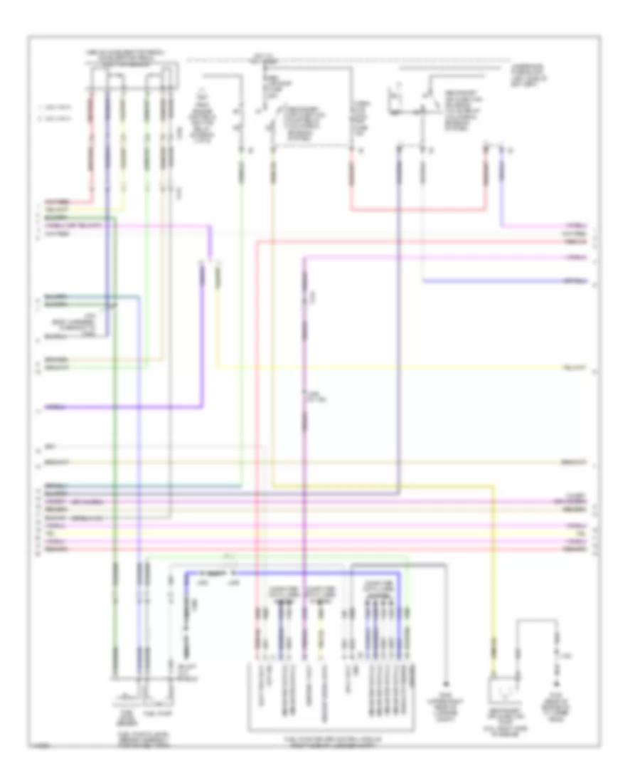
2.4L VIN R, Engine Controls Wiring Diagram (2 of 6) for Chevrolet Malibu LT 2013
List of elements for 2.4L VIN R, Engine Controls Wiring Diagram (2 of 6) for Chevrolet Malibu LT 2013:
- (behind left front fascia) active grille air shutter actuator
- (body harness, right side of luggage compt on floor)
- 5 volt ref
- Ccm fuse 20a
- Coil odd fuse 15a
- Computer data lines system
- Drain wire
- Ecm fuse 20a
- Ecm ign fuse 15a
- Engine controls ignition relay
- Engine coolant temperature sensor (right rear of engine)
- Exhaust camshaft position actuator solenoid valve (top front of engine)
- Fuel pressure sensor (right side of fuel tank)
- Fuel pump
- Fuel pump control module (right side of luggage compt)
- G101 (left front of engine compt)
- G405 (upper right rear of luggage compt)
- Gnd
- Hot at all times
- Hot in run or start
- Hs gmlan+
- Hs gmlan-
- Ignition main relay
- J101
- J303
- J406 (w/ vri)
- J445
- Logic
- Low ref
- Nca
- Non walk 02 fuse 10a
- Pmry rly ctrl ign
- Pt rc ign fuse 7.5a
- Relay ctrl
- Sens sig
- Sol ctrl
- Srl data
- Tc fscm ign fuse 7.5a
- To secondary air injection pump relay (diagram 5 of 6)
- Underhood fuse block (left side of battery)
- Wakeup
- X115
- X125
- X150
- X350
2.4L VIN R, Engine Controls Wiring Diagram (3 of 6) for Chevrolet Malibu LT 2013
List of elements for 2.4L VIN R, Engine Controls Wiring Diagram (3 of 6) for Chevrolet Malibu LT 2013:
- (near left headlamp assembly)
- (on camshaft cover) ignition coil 1
- (on camshaft cover) ignition coil 2
- (on camshaft cover) ignition coil 3
- (on camshaft cover) ignition coil 4
- 5-volt 2 ref
- Actu hi ctrl
- Actu low ctrl
- Cam pos intake
- Computer data lines system
- Crank sens sig
- Ctrl cylinder 1
- Ctrl cylinder 2
- Ctrl cylinder 3
- Ctrl cylinder 4
- Data
- Ect sens sig
- Eng ind ctrl
- Engine control module (ecm) (left side of engine compt)
- Engine coolant temperature gauge
- Exh sens
- Exhaust sol
- Fuel gauge
- G122 (rear of engine on cylinder head)
- Gmlan serial
- High pressure fuel pump (top rear of engine)
- Ign ctrl 1
- Ign ctrl 2
- Ign ctrl 3
- Ign ctrl 4
- Instrument panel cluster (ipc)
- Intake sens
- Intake sol
- J106
- J108
- J118
- J122
- Logic
- Low ref
- Low ref (1)
- Low ref bank 1
- Malfunction ind lamp (mil)
- Nca
- Oil level ind lamp
- Oil press sw sig
- Spark plug
- Sply volt
- X210
2.4L VIN R, Engine Controls Wiring Diagram (4 of 6) for Chevrolet Malibu LT 2013
List of elements for 2.4L VIN R, Engine Controls Wiring Diagram (4 of 6) for Chevrolet Malibu LT 2013:
- (lower right rear of engine) evaporative emission purge solenoid valve
- (top left of engine) fuel injector 2
- (top left of engine) fuel injector 3
- (top left of engine) fuel injector 4
- Crankshaft position sensor (left rear of engine)
- Engine control module (ecm) (left side of engine compt)
- Engine oil pressure switch
- Exhaust camshaft position sensor (rear of cylinder head)
- G121 (on engine rear of a/c compressor)
- Gnd
- Intake camshaft position actuator solenoid valve (rear of cylinder head)
- Intake camshaft position sensor (rear of cylinder head)
- J121
- Low ref
- Sply cyl 1
- Sply cyl 2
- Sply cyl 3
- Sply cyl 4
- X160
2.4L VIN R, Engine Controls Wiring Diagram (5 of 6) for Chevrolet Malibu LT 2013
List of elements for 2.4L VIN R, Engine Controls Wiring Diagram (5 of 6) for Chevrolet Malibu LT 2013:
- (top left of engine)
- Cylinder 1/2 secondary air injection solenoid valve (w/ california emission system) (above exhaust manifold towards front of engine)
- Cylinder 3/4 secondary air injection solenoid valve (w/ california emission system) (above exhaust manifold towards rear of engine)
- From engine controls relay (diagram 2 of 6)
- Fuel injector 1
- G122 (rear of engine on cylinder head)
- Hot at all times
- J120
- J132 (between x120 & right turn lamps)
- Sail sol fuse 15a
- Sec air pump fuse 50a
- Secondary air injection pump (left side of engine)
- Secondary air injection pump relay (california emission system)
- Secondary air injection solenoid valve relay (california emission system)
- Underhood fuse block (left side of battery)
- X114
- X115
- X160
2.4L VIN R, Engine Controls Wiring Diagram (6 of 6) for Chevrolet Malibu LT 2013
List of elements for 2.4L VIN R, Engine Controls Wiring Diagram (6 of 6) for Chevrolet Malibu LT 2013:
- (above catalytic converter) heated oxygen sensor 1
- (below catalytic converter) heated oxygen sensor 2
- 5v ref
- 5v ref fuel rail press sens sig
- Air temp sens sig
- Bank 1 sens 1
- Bank 1 sens 2
- Cool ctrl
- Cooling fans system
- Engine control
- Fuel rail pressure sensor (left side of engine)
- G121 (on engine rear of a/c compressor)
- Gnd
- Hi sig bank 1 sens1
- Hi sig bank 1 sens2
- J121
- Knock sens ref
- Knock sens sig
- Knock sensor (rear of engine near exhaust manifold)
- Low ref
- Maf sens sig
- Manifold absolute pressure (map) sensor (near throttle body)
- Map sens sig
- Mass air flow/ intake air temperature sensor (on upper air cleaner assembly)
- Module (ecm) (left side of engine compt)
- Nca
- Pump press sens sig
- Purge sol ctrl
- Sens sply volt
- Tac close
- Tac open
- Throttle body (left side of engine)
- Tps sig
- Transmission park/ neutral signal
- Transmissions system
- X160
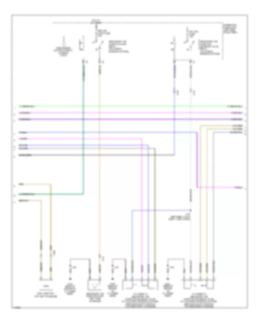
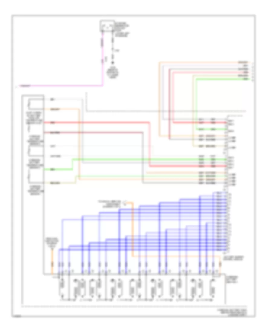
2.4L VIN R, Hybrid System Wiring Diagram (1 of 4) for Chevrolet Malibu LT 2013
List of elements for 2.4L VIN R, Hybrid System Wiring Diagram (1 of 4) for Chevrolet Malibu LT 2013:
- (between x110 & left headlamp)
- Acc wkup serial data
- Apm fuse 175a
- Auto disconnect ctrl
- Auxiliary transmission fluid pump relay
- Brake pedal position sensor
- Brk pos snsr 5
- Brk pos snsr low
- Brk pos snsr sig
- Computer data lines system
- Coolant pump relay coil control
- Driver motor control module 1
- Hot at all times
- Hot w/ engine controls ignition relay energized
- Hybrid/ev battery pack (behind rear seats in luggage compt)
- Hybrid/ev powertrain control module
- J121 (between throttle body breakout & ecm branch)
- J122 (on ecm x2 breakout) nca
- J123 (body harness near fuse block- underhood)
- J124
- J126
- J127
- J128
- J129
- Nca
- Pnk
- Red
- Resolver cosine signal drain wire
- Resolver motor drain wire
- Resolver mtr positive
- Resolver signal 1
- Resolver signal 2
- Resolver signal 3
- Resolver signal 4
- Resolver sine signal drain wire
- Starter/generator
- Starter/generator control module
- Three phase motor temp drain wire
- Three phase motor temp low refrence
- Three phase motor temp sig
- Trans aux pump b+ fuse 25a
- Trns aux oil pump
- U phase
- Underhood fuse block (left side of battery)
- V phase
- W phase
- X10
- X115
- X210
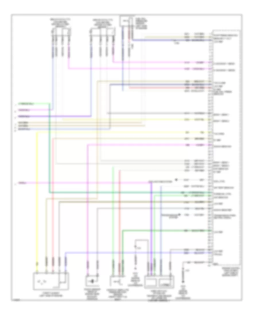
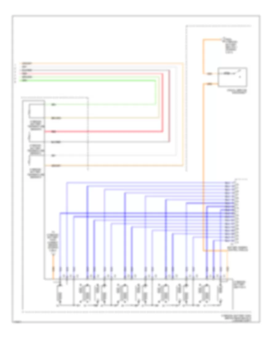
2.4L VIN R, Hybrid System Wiring Diagram (2 of 4) for Chevrolet Malibu LT 2013
List of elements for 2.4L VIN R, Hybrid System Wiring Diagram (2 of 4) for Chevrolet Malibu LT 2013:
- (top of transmission) auxiliary transmission fluid pump
- 130v+
- 130v-
- Acc wakeup sig
- Batt pos volt
- Batt positive
- Batt positive voltage
- Battery energy control module
- Battery positive
- Bpim batt fuse 7.5a
- Bpim fuse 15a
- Bpim ign fuse 7.5a
- Can bus
- Computer data lines system
- Coolant temp snsr sig
- Current snsr low
- Current snsr sig
- Current snsr sply
- Fan spd sig (1)
- Fan spd sig (2)
- Fan spd snsr
- Fan speed snsr
- From hybrid/ev battery section 2 (diagram 4 of 4)
- G122 (rear of engine on cylinder head)
- G401 (left rear wheel well in luggage compt)
- Ground
- High speed gmlan
- High voltage relay
- Hot at all times
- Hot w/ engine controls ignition relay energized
- Hot w/ ignition main relay energized
- Hybrid/ev battery pack (behind rear seats in luggage compt)
- Hybrid/ev battery pack cable cover
- Hybrid/ev battery pack cooling fan (under right rear shelf)
- Hybrid/ev battery pack current sensor
- Hybrid/ev battery pre-charge resistor
- Hybrid/ev powertrain control module
- Interlock loop lo ref
- J120
- J399
- J401
- J402
- Logic
- Loop signal
- Main contactor
- Mgu cool pump fuse 10a
- Nca
- Pnk
- Pre-charge contactor
- Pre-charge relay
- Red
- Reference
- Run/crank ign 1
- Run/crank ignition 1
- Serial data (+)
- Serial data (-)
- Serial data accessory wakeup
- Snsr low reference
- Sply volt fan spd sig (1)
- Starter/ generator coolant pump relay
- Starter/generator control module
- Starter/generator coolant temperature sensor (right front side of engine compt)
- To hybrid/ev battery section 1 (diagram 3 of 4)
- Underhood fuse block (left side of battery)
- X115
- X150
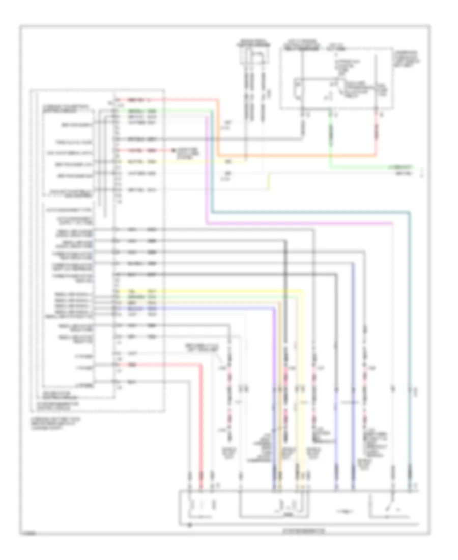
2.4L VIN R, Hybrid System Wiring Diagram (3 of 4) for Chevrolet Malibu LT 2013
List of elements for 2.4L VIN R, Hybrid System Wiring Diagram (3 of 4) for Chevrolet Malibu LT 2013:
- Battery energy control module
- From main contactor (diagram 2 of 4)
- G122 (rear of engine on cylinder head)
- Hybrid/ev battery pack (behind rear seats in luggage compt)
- Hybrid/ev battery section 1
- Hybrid/ev battery temperature sensor 1
- Hybrid/ev battery temperature sensor 2
- Hybrid/ev battery temperature sensor 3
- Inlet hybrid/ ev battery pack air temperature sensor inlet
- J120
- Lo ref
- Red
- Sig 1
- Sig 2
- Sig 3
- Sig 4
- Sig 5
- Sig 6
- Sig 7
- Starter/ generator coolant pump (lower left of engine)
- To manual service disconnect (diagram 4 of 4)
- X115
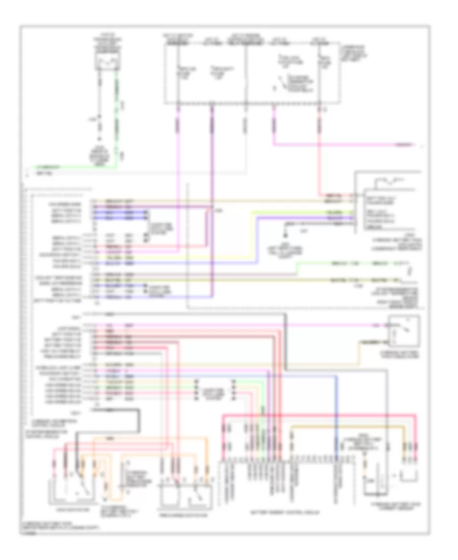
2.4L VIN R, Hybrid System Wiring Diagram (4 of 4) for Chevrolet Malibu LT 2013
List of elements for 2.4L VIN R, Hybrid System Wiring Diagram (4 of 4) for Chevrolet Malibu LT 2013:
- 125a
- Battery energy control module
- From hybrid/ev battery section 1 (diagram 3 of 4)
- Hybrid/ev battery pack (behind rear seats in luggage compt)
- Hybrid/ev battery section 2
- Hybrid/ev battery temperature sensor 4
- Hybrid/ev battery temperature sensor 5
- Hybrid/ev battery temperature sensor 6
- Manual service disconnect
- Red
- T0 hybrid/ev battery pack current sensor (diagram 2 of 4)
2.5L VIN A
2.5L VIN A, Engine Performance Wiring Diagram (1 of 6) for Chevrolet Malibu LT 2013
List of elements for 2.5L VIN A, Engine Performance Wiring Diagram (1 of 6) for Chevrolet Malibu LT 2013:
- (or 3200)
- (or 3201)
- 2.0l vin x
- 2.5l vin a
- 5-v ref
- 5v ref
- A/c compressor clutch rly ctrl
- A/c press sens 5v ref
- A/c refrigerant press sens lo ref
- A/c refrigerant pressure sens sig
- A/c refrigerant pressure sensor (right side of a/c condenser)
- Accessory wakeup serial data
- Air conditioning system
- Air pressure sig
- App lo ref
- App low ref
- App sens sig (1)
- App sens sig (2)
- Batt pos vol
- Brk pos sen sig
- Brk pos sens 5v ref
- Brk pos sens low ref
- Check engine ind ctrl
- Computer data lines system
- Coolant temp sens sig (2)
- Cooling fans system
- Cruise control system
- Cruise\etc\tcc brk sig
- Engine control module (ecm) (left side of engine compt)
- Engine coolant temperature sensor 2 (lower right side of radiator)
- Evap conister vent sol ctrl
- Evaporative emission vent solenoid valve (right side of fuel tank)
- Exterior lights system
- Fuel level sens lo ref
- Fuel level sens sig
- Fuel line press sens 5v ref
- Fuel line pressure sens lo ref
- Fuel line pressure sens sig
- Fuel pressure sensor (right side of fuel tank)
- Fuel pump controller data out sig
- Fuel tank pressure sens sig
- Fuel tank pressure sensor (top of fuel tank)
- Hi spd cooling fan rly ctrl
- Hi spd gmlan serial data (+)
- Hi spd gmlan serial data (-)
- Low ref
- Low speed cooling fan rly ctrl
- Main relay fused sply
- Powertrain main rly fused sply (1)
- Powertrain rly coil ctrl
- Pre-throttle air press temp sig
- Reaction pump rly coil ctrl
- Reaction solenoid rly coil ctrl
- Run/crank ign 1 vol
- Sens 2 low ref
- Starter enable rly ctrl
- Starting/charging system
- Throttle inlet absolute pressure sensor (2.0l vin x) (on throttle inlet tube near ecm)
- Underhood fuse block (left side of battery) x3
- X115
- X117
- X350
2.5L VIN A, Engine Performance Wiring Diagram (2 of 6) for Chevrolet Malibu LT 2013
List of elements for 2.5L VIN A, Engine Performance Wiring Diagram (2 of 6) for Chevrolet Malibu LT 2013:
- (above accelerator pedal) accelerator pedal position sensor
- 2.0l vin x
- 2.5l vin a
- Batt pos volt
- Cabin htr cool pmp fuse 15a
- Computer data lines system
- From engine controls ignition relay (diagram 3 of 6)
- Fuel level sensor
- Fuel pump
- Fuel pump & level sensor assembly (top of fuel tank)
- Fuel pump driver control module (right side of luggage compt)
- G122 (rear of engine on cylinder head)
- G405 (upper right rear of luggage compt)
- Gmlan ser data (+)
- Gmlan ser data (-)
- Gnd
- Hot at all times
- Ignition 1 volt
- J120
- J406 (w/ vri)
- J434 (body harness, in branch to x420)
- J435
- J436
- Low ref
- Nca
- Out sig
- Sec air pump fuse 50a
- Secondary air injection pump (2.5l: right side of engine)
- Secondary air injection pump relay (california emission system)
- Secondary air injection solenoid valve relay (california emission system)
- Shield extension
- Sply volt
- Underhood fuse block (left side of battery)
- Wakeup serial data
- X115
- X210
- X350
2.5L VIN A, Engine Performance Wiring Diagram (3 of 6) for Chevrolet Malibu LT 2013
List of elements for 2.5L VIN A, Engine Performance Wiring Diagram (3 of 6) for Chevrolet Malibu LT 2013:
- Coil odd fuse 15a
- Cps fuse 10a
- Ecm batt fuse 15a
- Ecm fuse 20a
- Ecm ign fuse 5a
- Engine controls ignition relay
- Engine coolant temperature sensor 1 (top rear of engine)
- Engine oil pressure sensor (right side of engine)
- Exhaust camshaft position actuator solenoid valve (top front of engine)
- Fscm fuse 20a
- Fuse 7.5a
- G101 (left front of engine compt)
- G122 (rear of engine on cylinder head)
- High pressure fuel pump (top rear of engine)
- Hot at all times
- Hot in run or start
- Ignition main relay
- J120
- Mil ign fuse 5a
- Non walk o2 fuse 10a
- Non walk veh fuse 10a
- Red
- Secondary air injection solenoid valve (california emission system) (2.5l: top rear of engine)
- To secondary air injection pump relay (diagram 2 of 6)
- Underhood fuse block (left side of battery)
2.5L VIN A, Engine Performance Wiring Diagram (4 of 6) for Chevrolet Malibu LT 2013
List of elements for 2.5L VIN A, Engine Performance Wiring Diagram (4 of 6) for Chevrolet Malibu LT 2013:
- (near exhaust camshaft position sensor breakout)
- (on camshaft cover)
- 5v ref
- Actuator hi ctrl
- Actuator low ctrl
- Camshaft pos intake
- Computer data lines system
- Crankshaft 60x sens volt
- Crankshaft sens sig
- Ctrl cylinder 1
- Ctrl cylinder 2
- Ctrl cylinder 3
- Ctrl cylinder 4
- Data
- Driver information center (dic)
- Ect sens sig
- Engine control module (ecm) (left side of engine compt)
- Exhaust sens (1)
- Exhaust sol (1)
- G122 (rear of engine on cylinder head)
- G203 (left kick panel)
- Gnd
- Ic ctrl (1)
- Ic ctrl (2)
- Ic ctrl (3)
- Ic ctrl (4)
- Ign
- Ignition coil 1
- Ignition coil 2
- Ignition coil 3
- Ignition coil 4
- Instrument cluster
- Intake sol (1)
- J103 (between intake camshaft position sensor & evaporative emission purge solenoid valve breakouts)
- J106
- J108 (near x160 breakout)
- J122
- J203
- Logic
- Low ref
- Low ref bank 1
- Malfunction ind lamp (mil)
- Nca
- Oil level ind lamp
- Oil press sens sig
- Red
- Sens lo ref
- Serial gmlan
- Spark plug
- Sply volt
- X210
2.5L VIN A, Engine Performance Wiring Diagram (5 of 6) for Chevrolet Malibu LT 2013
List of elements for 2.5L VIN A, Engine Performance Wiring Diagram (5 of 6) for Chevrolet Malibu LT 2013:
- (2.0l: top right rear of engine) (2.5l: top right front of engine) evaporative emission purge solenoid valve
- (above a/c compressor) (2.0l vin x) turbocharger bypass solenoid valve
- (left side of engine) engine oil pressure control solenoid valve
- (top right of engine)
- (top right of engine) fuel injector 2
- (top right of engine) fuel injector 3
- (top right of engine) fuel injector 4
- Battery fuse block (on battery)
- Crankshaft position sensor (right rear of engine)
- Engine control module (ecm) (left side of engine compt)
- Engine oil level switch (right side of oil pan)
- Exhaust camshaft position sensor (front of cylinder head)
- Fuel injector 1
- Fuse 250a
- G121 (on engine rear of a/c compressor)
- Gnd
- Hot at all times
- Intake camshaft position actuator solenoid valve (top front of engine)
- Intake camshaft position sensor (front of cylinder head)
- J121
- Low ref
- Red
- Sply cylinder 1
- Sply cylinder 2
- Sply cylinder 3
- Sply cylinder 4
- Turbocharger wastegate solenoid valve (2.0l vin x) (above a/c compressor)
- X160
2.5L VIN A, Engine Performance Wiring Diagram (6 of 6) for Chevrolet Malibu LT 2013
List of elements for 2.5L VIN A, Engine Performance Wiring Diagram (6 of 6) for Chevrolet Malibu LT 2013:
- (above catalytic converter) heated oxygen sensor 1
- (below catalytic converter) heated oxygen sensor 2
- (on upper air cleaner assembly) multifunction intake air sensor
- 2.0l vin x
- 2.5l vin a
- 5v ref
- 5v ref fuel rail press sens sig
- Air temp low ref
- Air temp sens sig
- Bank 1 sens (1)
- Bank 1 sens (2)
- Charge ind ctrl
- Ctrl bank (1)
- Engine control module (ecm) (left side of engine compt)
- Engine coolant thermostat heater (left side of engine near thermostat)
- Fuel rail pressure sensor (left side of engine)
- G121 (on engine rear of a/c compressor)
- Generator field
- Gnd
- Hi sig bank 1 sens (1)
- Hi sig bank 1 sens (2)
- J107
- J121
- Knock sens
- Knock sens sig
- Knock sens transmission park/ neutral signal (1) command sig
- Knock sensor 1 (2.0l vin x) knock sensor 2 (2.5l vin a) (right side of engine)
- Knock sensor 2 (2.0l vin x) knock sensor 1 (2.5l vin a) (right side of engine)
- Low ref
- Maf sens sig
- Manifold absolute pressure sensor (near throttle body)
- Map low ref
- Map sens sig
- Nca
- Oil level sw sig
- Purge sol ctrl
- Ref bank (1)
- Sens sig
- Sens sig bank (1)
- Sply volt
- Starting/charging system
- Tac close
- Tac open
- Throttle body (right side of engine)
- Tp sens sig waste gate sol ctrl cool ctrl
- Transmissions system
- X160