ENGINE PERFORMANCE
2.2L VIN F
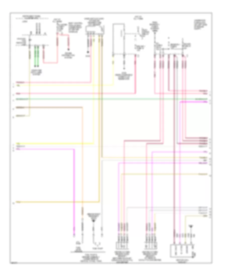
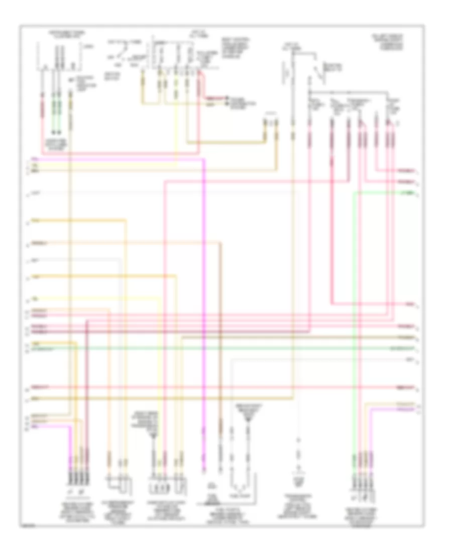
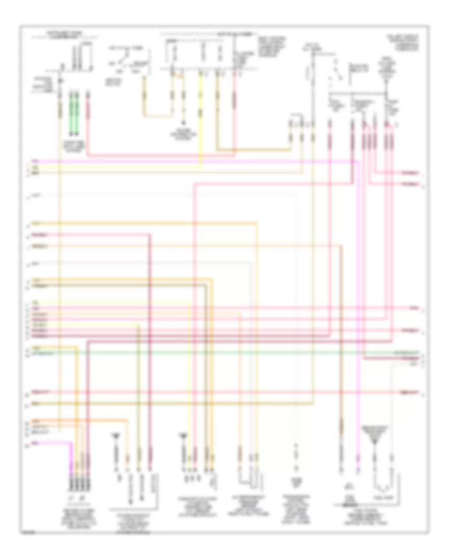
2.2L VIN F, Engine Performance Wiring Diagram (1 of 4) for Chevrolet Malibu Maxx SS 2007

List of elements for 2.2L VIN F, Engine Performance Wiring Diagram (1 of 4) for Chevrolet Malibu Maxx SS 2007:
- (left side of engine compt, forward of battery)
- 12v coil ctrl
- 5v ref 1
- 5v ref 2
- A/c refrigerant pressure sensor (left of right front strut tower)
- A/c relay ctrl
- A/c sens sig
- Acc
- Accelerator pedal position (app) sensor (attached to accelerator pedal)
- Accessory volt
- Air conditioning system
- App sens 1 sig
- App sens 2 sig
- B11
- Battery volt
- Body control logic module (bcm) (under front of center console)
- Computer data lines system
- Cooling fans system
- Ctrl coil
- D12
- Ecm fuse 13 10a
- Emission 1 fuse 6 10a
- Engine control module (ecm)
- Etc fuse 2 15a
- Evap vent ctrl
- Evaporative emission (evap) canister vent solenoid valve (extended sedan: under rear of vehicle, above fuel tank)
- Exterior lights system
- Fan relay ctrl
- Fuel sens sig
- Fuel tank pressure (ftp) sensor (under rear of vehicle)
- Hot at all times
- Iat sens sig
- Ign 1 volt
- Ignition switch
- Lamp sw sig
- Low ref
- Maf sens sig
- Mil ctrl
- Off
- Park/neutral sig
- Pnk
- Power distribution system
- Pwr/trn relay 33
- Relay ctrl
- Run
- Sens sig
- Ser data bus+
- Ser data bus-
- Start
- Starting/charging system
- Tan
- Tan c
- To inj fuse 5 (diagram 2 of 4)
- Underhood fuse block (on left side of engine compt)
- Voltage
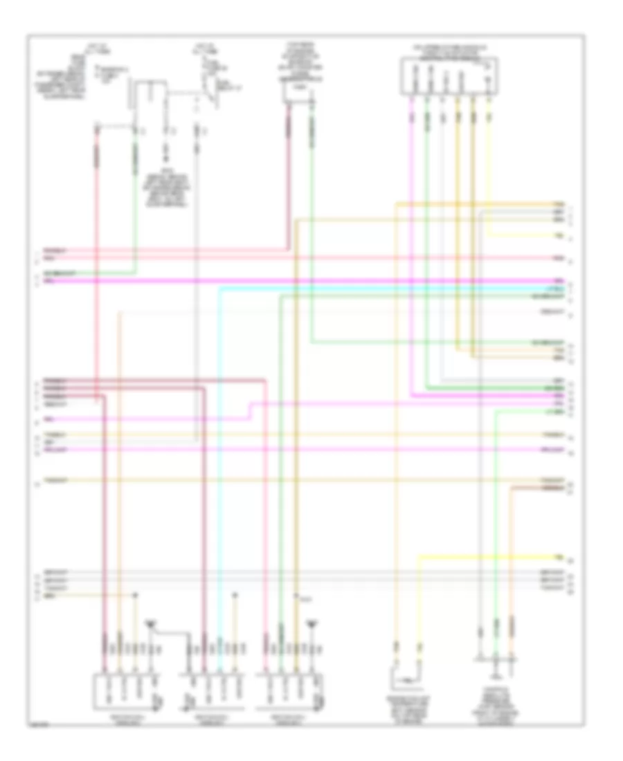
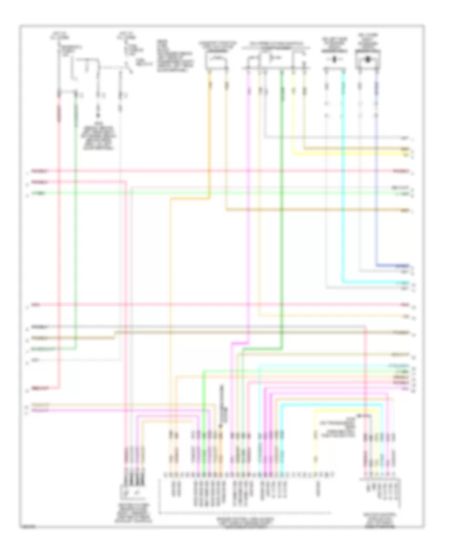
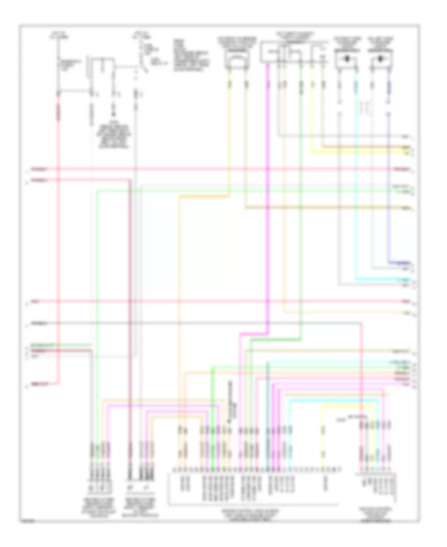
2.2L VIN F, Engine Performance Wiring Diagram (2 of 4) for Chevrolet Malibu Maxx SS 2007
List of elements for 2.2L VIN F, Engine Performance Wiring Diagram (2 of 4) for Chevrolet Malibu Maxx SS 2007:
- (behind right rear seat back) g301
- A10
- Body control module (bcm) (under front of center console)
- C10
- C11
- Case gnd
- Cluster/ theft fuse 10a
- Computer data lines system
- D11
- Ecm ign 1 fuse 16 10a
- Emission 1 fuse 6 10a
- From emission 1 fuse 6 (diargam 1 of 4)
- Fuel level sensor
- Fuel pump
- Fuel pump & sender assembly (under rear of vehicle, in fuel tank)
- G105
- G109 (near windshield wiper fluid reservoir)
- G110
- Gmlan data
- Gnd
- Heated oxygen sensor (ho2s) sensor 1 (between exhaust manifold & catalytic converter)
- Heated oxygen sensor (ho2s) sensor 2 (at rear of catalytic converter)
- Hot at all times
- Ic 1 ctrl
- Ign
- Ign 1 volt
- Ign mod fuse 43 15a
- Ignition coil/ module 1
- Inj fuse 5 or 44 10a
- Instrument panel cluster (ipc)
- Logic
- Low ref
- Malfunc- tion indicator lamp
- Mass air flow (maf)/ intake air temperature (iat) sensor
- Nca
- Pnk
- Power distribution system
- Run/ crank relay
- Tan
- Underhood fuse block (on left side of engine compt)
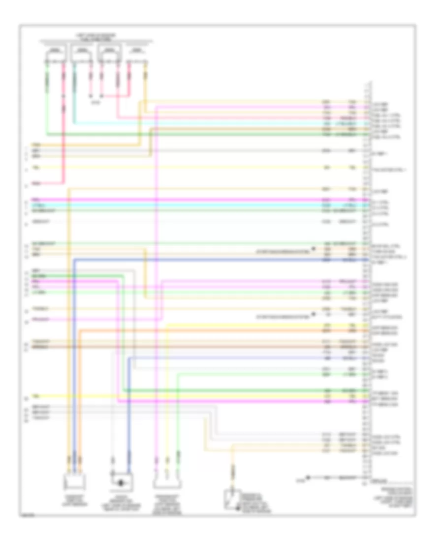
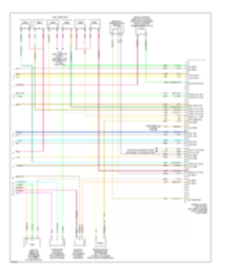
2.2L VIN F, Engine Performance Wiring Diagram (3 of 4) for Chevrolet Malibu Maxx SS 2007
List of elements for 2.2L VIN F, Engine Performance Wiring Diagram (3 of 4) for Chevrolet Malibu Maxx SS 2007:
- (on upper intake manifold) throttle actuator control (tac) module
- (sedan: behind left rear seat) (extended sedan: behind rear seat, on left quarterpanel)
- (top rear of engine) evaporative emission (evap) canister purge solenoid valve
- 5v ref 2
- A10
- Case gnd
- Emission 2 fuse 5 10a
- Engine coolant temperature (ect) sensor (on top rear of engine)
- Fuel fuse 25 15a
- Fuel relay 37
- G110
- G302
- Gnd
- Gnd case
- Hot at all times
- Ic 2 ctrl
- Ic 3 ctrl
- Ic 4 ctrl
- Ign 1 volt
- Ignition coil/ module 2
- Ignition coil/ module 3
- Ignition coil/ module 4
- Low ref
- Manifold absolute pressure (map) sensor (front of engine, at cylinder 3 intake port)
- Pnk
- Rear fuse block (extended sedan: left rear of passenger compt) (sedan: left rear quarterpanel)
- S121
- Sens 1 sig
- Sens 2 sig
- Tan
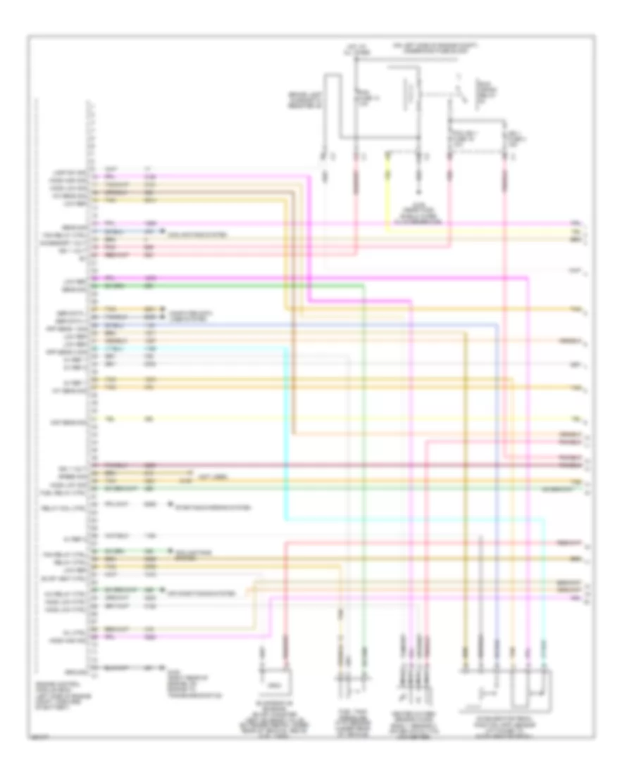
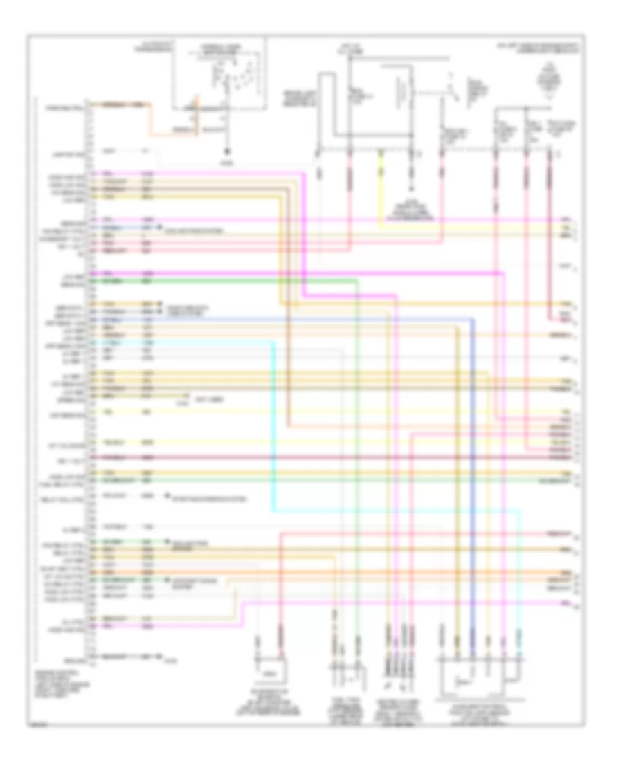
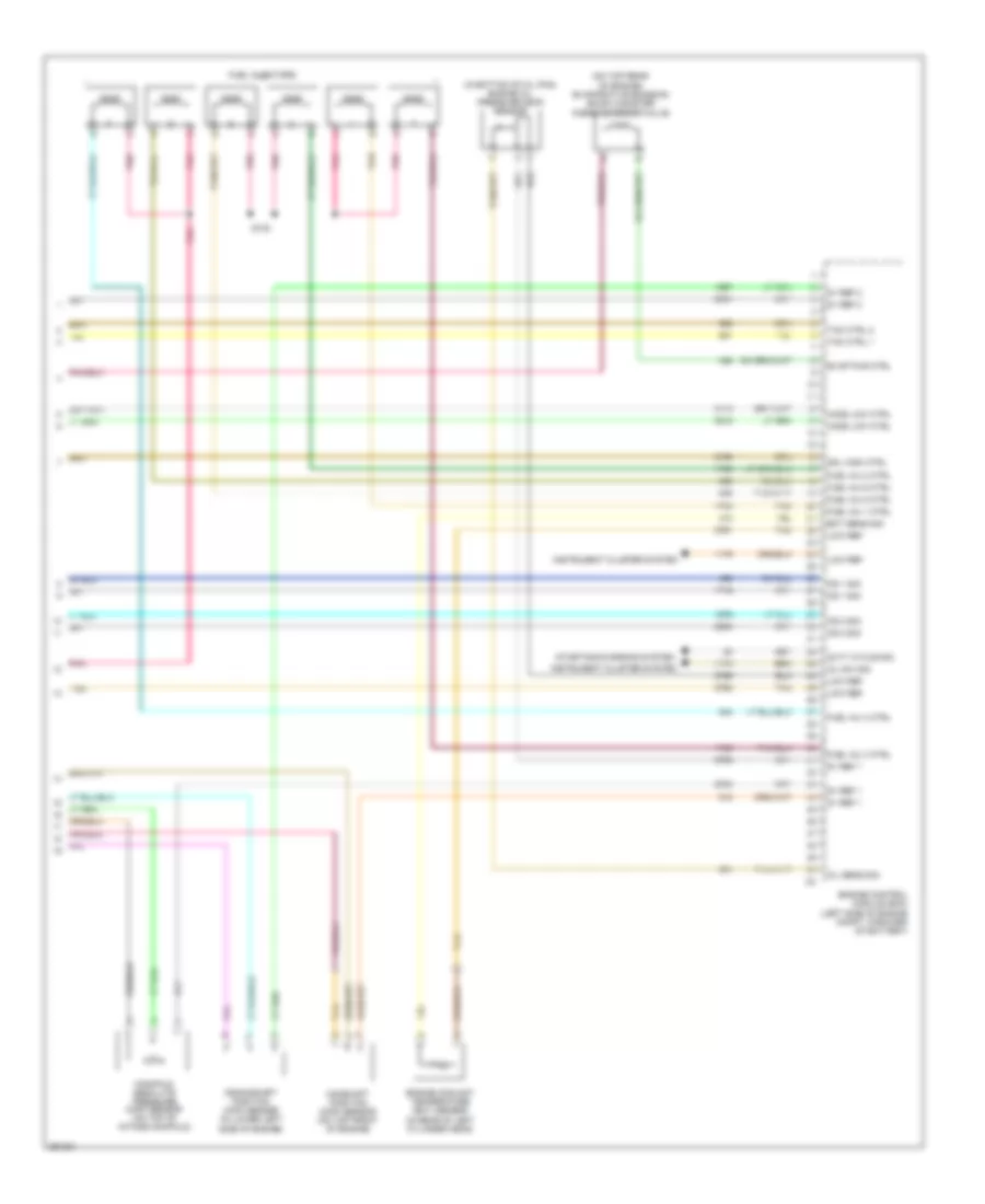
2.2L VIN F, Engine Performance Wiring Diagram (4 of 4) for Chevrolet Malibu Maxx SS 2007
List of elements for 2.2L VIN F, Engine Performance Wiring Diagram (4 of 4) for Chevrolet Malibu Maxx SS 2007:
- (left side of engine compt, forward of battery)
- (left side of engine) fuel injectors
- 5v ref 1
- 5v ref 2
- Camshaft position (cmp) sensor
- Ckp sens sig
- Cmp sens sig
- Crankshaft position (ckp) sensor (on rear left side of engine)
- Duty cycle sig
- Ect sens sig
- Engine control module (ecm)
- Engine oil pressure (eop) switch (on rear left side of engine)
- Evap sol ctrl
- Fuel inj 1 ctrl
- Fuel inj 2 ctrl
- Fuel inj 3 ctrl
- Fuel inj 4 ctrl
- G105
- Ground
- Ho2s high sig
- Ho2s low ctrl
- Ho2s low sig
- Ic 1 ctrl
- Ic 2 ctrl
- Ic 3 ctrl
- Ic 4 ctrl
- Knock sensor (ks) (left side of engine, near oil dipstick)
- Ks sig
- Low ref
- Map sens sig
- Pnk
- S130
- Starting/charging system
- Sw sig
- Tac motor ctrl 1
- Tac motor ctrl 2
- Tan
- Tp sens 1 sig
- Tp sens 2 sig
- Turn on sig
3.5L VIN N
3.5L VIN N, Engine Performance Wiring Diagram (1 of 4) for Chevrolet Malibu Maxx SS 2007
List of elements for 3.5L VIN N, Engine Performance Wiring Diagram (1 of 4) for Chevrolet Malibu Maxx SS 2007:
- (left side of engine compt, forward of battery)
- (not used)
- (on left side of engine compt) underhood fuse block
- 5v ref 1
- 5v ref 2
- A/c relay ctrl
- A/c sens sig
- Accelerator pedal position (app) sensor (attached to accelerator pedal)
- Accessory volt
- Air conditioning system
- App sens 1 sig
- App sens 2 sig
- Brake lamp diagnostic resister 46
- C10
- C100
- Computer data lines system
- Cooling fans system
- Engine control module (ecm)
- Evap vent ctrl
- Evaporative emission (evap) canister vent solenoid valve (extended sedan: under rear of vehicle, above fuel tank)
- Fan relay ctrl
- Fuel relay ctrl
- Fuel tank pressure (ftp) sensor (under rear of vehicle)
- G105 (right rear of engine, on engine to transmission stud)
- G109 (near wind- shield wiper fluid reservoir)
- Ground
- Heated oxygen sensor (ho2s) bank 1 sensor 2 (after catalytic) converter)
- Ho2s high sig
- Ho2s low ctrl
- Ho2s low sig
- Hot at all times
- Iat sens sig
- Ign 1 fuse 3 15a
- Ign 1 volt
- Lamp sw sig
- Low ref
- Maf sens sig
- Mil ctrl
- Nca
- Pcm fuse 13 10a
- Pcm ign 1 fuse 16 10a
- Pnk
- Relay coil ctrl
- Relay ctrl
- Run/ crank relay
- Sens sig
- Ser data +
- Ser data -
- Speed sig
- Starting/charging system
- Tan
- Tan c
3.5L VIN N, Engine Performance Wiring Diagram (2 of 4) for Chevrolet Malibu Maxx SS 2007
List of elements for 3.5L VIN N, Engine Performance Wiring Diagram (2 of 4) for Chevrolet Malibu Maxx SS 2007:
- (after catalytic) converter)
- (behind right rear seat back) g301
- (on left side of engine compt) underhood fuse block
- (right rear of engine, on engine to transmission stud) g105
- A/c refrigerant pressure sensor (left of right front strut tower)
- A10
- Acc
- Acc vol
- B11
- Body control module (bcm) (under front of center console)
- C11
- Cluster/ theft fuse 10a
- Coil ctrl
- Computer data lines system
- D11
- Emission 1 fuse 6 10a
- Etc fuse 2 15a
- Fuel level sensor
- Fuel pump
- Fuel pump & sender assembly (under rear of vehicle, in fuel tank)
- Gmlan data
- Gnd
- Heated oxygen sensor (ho2s) bank 2 sensor 1 (on exhaust manifold)
- Heated oxygen sensor (ho2s) bank 2 sensor 2
- Hot at all times
- Ign
- Ignition switch
- Inj fuse 5 or 44 10a
- Instrument panel cluster (ipc)
- Logic
- Malfunc- tion indicator lamp
- Mass air flow (maf)/ intake air temperature (iat) sensor (in intake air duct)
- Nca
- Off
- Pnk
- Post fuse 10a
- Power distribution system
- Pwr/trn relay 33
- Run
- Sig
- Start
- Stop lamp sw
- Tan
- Tan a
- Transmission control module (tcm) (left rear of engine compt, near strut tower)
3.5L VIN N, Engine Performance Wiring Diagram (3 of 4) for Chevrolet Malibu Maxx SS 2007
List of elements for 3.5L VIN N, Engine Performance Wiring Diagram (3 of 4) for Chevrolet Malibu Maxx SS 2007:
- (on left side of engine) knock sensor (ks) 2
- (on lower right of engine) knock sensor (ks) 1
- (on upper intake manifold) throttle body
- (sedan: behind left rear seat) (extended sedan: behind rear seat, on left quarterpanel)
- A10
- Camshaft position (cpm) actuator solenoid
- Cpm sens sig
- Emission 2 fuse 5 10a
- Engine control module (ecm) (left side of engine compt, forward of battery)
- Fuel fuse 25 15a
- Fuel relay 37
- G106 (on transmission, near park/neutral position switch)
- G302
- Gnd
- Heated oxygen sensor (ho2s) bank 1 sensor 1 (center of rear exhaust manifold)
- Ho2s high sig
- Ho2s low sig
- Hot at all times
- Ic 1 ctrl
- Ic 2 ctrl
- Ic 3 ctrl
- Ign 1
- Ignition control module (icm) (on top right side of engine)
- Low ref
- Map sens sig
- Nca
- Nca nca
- Pnk
- Rear fuse block (extended sedan: left rear of passenger compt) (sedan: left rear quarterpanel)
- Speed sig
- Starting/charging system
- Tan
- Tp sens 1 sig
- Tp sens 2 sig
- Turn on sig
3.5L VIN N, Engine Performance Wiring Diagram (4 of 4) for Chevrolet Malibu Maxx SS 2007
List of elements for 3.5L VIN N, Engine Performance Wiring Diagram (4 of 4) for Chevrolet Malibu Maxx SS 2007:
- (left side of engine compt, forward of battery)
- (rear of engine, near throttle body) evaporative emission (evap) canister purge solenoid valve
- 5v ref 1
- 5v ref 2
- Camshaft position (cmp) sensor (on front of engine)
- Crankshaft position (ckp) sensor (on lower right side of engine)
- Duty cycle sig
- Ect sens sig
- Engine control module (ecm)
- Engine coolant temperature (ect) sensor (on right cylinder head, above transmission)
- Engine oil pressure (eop) sensor
- Evap pur ctrl
- Fuel inj 1 ctrl
- Fuel inj 2 ctrl
- Fuel inj 3 ctrl
- Fuel inj 4 ctrl
- Fuel inj 5 ctrl
- Fuel inj 6 ctrl
- Fuel injectors
- Ho2s low ctrl
- Instrument cluster system
- Ks 1 sig
- Ks 2 sig
- Low ref
- Manifold absolute pressure (map) sensor (in upper intake manifold)
- Oil sens sig
- Oil sw sig
- Pnk
- Pnk pnk
- S130 (fuel injector wiring harness, 4 cm from breakout to fuel injector 2)
- Sol high ctrl
- Starting/charging system
- Tac ctrl 1
- Tac ctrl 2
- Tan
3.9L VIN 1
3.9L VIN 1, Engine Performance Wiring Diagram (1 of 4) for Chevrolet Malibu Maxx SS 2007
List of elements for 3.9L VIN 1, Engine Performance Wiring Diagram (1 of 4) for Chevrolet Malibu Maxx SS 2007:
- (left side of engine compt, forward of battery)
- (not used)
- (on left side of engine compt) underhood fuse block
- 5v ref 1
- 5v ref 2
- A/c relay ctrl
- A/c sens sig
- A10
- Accelerator pedal position (app) sensor (attached to accelerator pedal)
- Accessory volt
- Air conditioning system
- App sens 1 sig
- App sens 2 sig
- Automatic transmission
- B11
- Brake lamp diagnostic resister 46
- C10
- C100
- Computer data lines system
- Cooling fans system
- Ecm fuse 13 10a
- Ecm ign 1 fuse 16 10a
- Engine control module (ecm)
- Evap vent ctrl
- Evaporative emission (evap) canister vent solenoid valve (on top rear of engine)
- Fan relay ctrl
- Fuel relay ctrl
- Fuel tank pressure (ftp) sensor (under rear of vehicle)
- G105
- G109 (near wind- shield wiper fluid reservoir)
- Ground
- Heated oxygen sensor (ho2s) bank 1 sensor 2 (after catalytic) converter)
- Ho2s high sig
- Ho2s low ctrl
- Ho2s low sig
- Hot at all times
- Iat sens sig
- Ign 1 fuse 15a
- Ign 1 volt
- Imt valve ctrl
- Imt valve sig
- Imtv/dod fuse 45 10a
- Inj fuse 5 or 44 10a
- Internal mode switch (ims)
- Lamp sw sig
- Low ref
- Maf sens sig
- Mil ctrl
- Nca
- Park/neutral
- Pnk
- Relay coil ctrl
- Relay ctrl
- Run/ crank relay
- Sens sig
- Ser data +
- Ser data -
- Speed sig
- Starting/charging system
- Tan
- Tan c
- To post o2 fuse (diargam 2 of 4)
3.9L VIN 1, Engine Performance Wiring Diagram (2 of 4) for Chevrolet Malibu Maxx SS 2007
List of elements for 3.9L VIN 1, Engine Performance Wiring Diagram (2 of 4) for Chevrolet Malibu Maxx SS 2007:
- (after catalytic) converter)
- (behind right rear seat back) g301
- (on left side of engine compt) underhood fuse block
- A/c refrigerant pressure sensor (left of right front strut tower)
- Acc
- Acc vol
- B11
- Batt vol
- Body control module (bcm) (under front of center console)
- C11
- Cluster/ theft fuse 10a
- Coil ctrl
- Computer data lines system
- D11
- Emission 1 fuse 6 10a
- Etc fuse 2 15a
- From imtv/dod fuse (diargam 1 of 4)
- Fuel level sensor
- Fuel pump
- Fuel pump & sender assembly (under rear of vehicle, in fuel tank)
- G105
- Gmlan data
- Gnd
- Heated oxygen sensor (ho2s) bank 2 sensor 2
- Hot at all times
- Ign
- Ignition switch
- Imt valve ctrl
- Imt valve sig
- Instrument panel cluster (ipc)
- Intake manifold tuning (imt) valve solenoid (on front of intake manifold)
- Logic
- Malfunc- tion indicator lamp
- Mass air flow (maf)/ intake air temperature (iat) sensor (in intake air duct)
- Nca
- Off
- Pnk
- Post fuse 10a
- Power distribution system
- Pwr/trn relay 33
- Run
- Sig
- Start
- Stop lamp sw
- Tan
- Tan a
- Transmission control module (tcm) (left rear of engine compt, near strut tower)
3.9L VIN 1, Engine Performance Wiring Diagram (3 of 4) for Chevrolet Malibu Maxx SS 2007
List of elements for 3.9L VIN 1, Engine Performance Wiring Diagram (3 of 4) for Chevrolet Malibu Maxx SS 2007:
- (on front of engine) camshaft position (cmp) actuator solenoid
- (on left side of engine) knock sensor (ks) 1
- (on right side of engine) knock sensor (ks) 2
- (on throttle body) throttle body assembly
- (sedan: behind left rear seat) (extended sedan: behind rear seat, on left quarterpanel)
- A10
- Cpm sens sig
- Emission 2 fuse 5 10a
- Engine control module (ecm) (left side of engine compt, forward of battery)
- Fuel fuse 25 15a
- Fuel relay 37
- G106
- G302
- Gnd
- Heated oxygen sensor (ho2s) bank 1 sensor 1 (in left exhaust manifold)
- Heated oxygen sensor (ho2s) bank 2 sensor 1 (in right exhaust manifold)
- Ho2s high sig
- Ho2s low sig
- Hot at all times
- Ic 1 ctrl
- Ic 2 ctrl
- Ic 3 ctrl
- Ign 1
- Ignition control module (icm) (on right side of engine)
- Low ref
- Map sens sig
- Nca
- Nca nca
- Pnk
- Rear fuse block (extended sedan: left rear of passenger compt) (sedan: left rear quarterpanel)
- Speed sig
- Starting/charging system
- Tan
- Tp sens 1 sig
- Tp sens 2 sig
- Turn on sig
3.9L VIN 1, Engine Performance Wiring Diagram (4 of 4) for Chevrolet Malibu Maxx SS 2007
List of elements for 3.9L VIN 1, Engine Performance Wiring Diagram (4 of 4) for Chevrolet Malibu Maxx SS 2007:
- (in bottom of oil pan) engine oil pressure (eop) sensor
- (left side of engine compt, forward of battery)
- (on top rear of engine) evaporative emission (evap) canister purge solenoid valve
- 5v ref 1
- 5v ref 2
- Camshaft position (cmp) sensor (on top front of engine)
- Crankshaft position (ckp) sensor (in lower left side of engine)
- Duty cycle sig
- Ect sens sig
- Engine control module (ecm)
- Engine coolant temperature (ect) sensor (in rear of left cylinder head)
- Evap pur ctrl
- Fuel inj 1 ctrl
- Fuel inj 2 ctrl
- Fuel inj 3 ctrl
- Fuel inj 4 ctrl
- Fuel inj 5 ctrl
- Fuel inj 6 ctrl
- Fuel injectors
- Ho2s low ctrl
- Instrument cluster system
- Ks 1 sig
- Ks 2 sig
- Low ref
- Manifold absolute pressure (map) sensor (on top of intake manifold)
- Oil sens sig
- Oil sw sig
- Pnk
- S130
- Sol high ctrl
- Starting/charging system
- Tac ctrl 1
- Tac ctrl 2
- Tan