ENGINE PERFORMANCE
1.0L
1.0L (VIN 6), Engine Performance Wiring Diagrams (1 of 2) for Chevrolet Metro 1998

List of elements for 1.0L (VIN 6), Engine Performance Wiring Diagrams (1 of 2) for Chevrolet Metro 1998:
- (center rear of engine) g115
- (engine harn, left rear of engine compt)
- (engine harness, near center of firewall) s262
- (main harness, left side of engine compt)
- (main harness, near junction block)
- A/c amplifier
- A/c cut-out
- Air conditioning system
- Camshaft position (cmp) sensor
- Ckp sensor
- Cmp sensor
- Cooling fan system
- Crankshaft position (ckp) sensor (bottom of engine, near crankshaft pulley)
- Data link connector on board diagnostics ii (dlc-obd ii) (left side of dash)
- Defogger system
- Diag request sig
- Diode module (behind center of dash)
- Distributor (left side of engine)
- Distributor cap
- Dome fuse 15a
- Duty check data link connector (left rear of engine compt)
- Early fuel evaporative (efe) heater (between intake manifold and red
- Early fuel evaporative heater relay (ptc htr)
- Ecm ground
- Ect input
- Efe on sig
- Egr bypass cntrl
- Egr sol cntrl
- Engine start sig
- Evap canister tank pressure control solenoid vacuum valve (top of fuel tank)
- Evap canister vent solenoid valve (rear of engine compt)
- Evap cann cntrl
- Evap cvsv ctrl
- Evap tpcsvv ctrl
- Fuel level
- Fuel pres
- Fuel pump relay
- Fuel tank pressure sensor (in fuel tank)
- Fuse box (left of eng compt, behind battery)
- G115 (center rear of engine, on intake manifold)
- Ground
- Ho2s1 heater
- Ho2s1 input
- Ho2s2 heater
- Ho2s2 input
- Hot at all times
- Iat input
- Idle switch sig
- Idle-up sig
- Ign coil control
- Ign pwr input
- Ign trig input ignition control module (left side of fire- wall)
- Ign trigger sig
- Ignition
- Ignition coil (left side of firewall)
- Inj control
- Instrument cluster system
- Instrument cluster system (tachometer)
- Interior lights system
- Isc motor cntrl
- Isca relay cntrl
- Junction block (behind left side of dash)
- Map input
- Memory power
- Mil ind control
- Nca
- Noise suppressor filter (left rear of firewall)
- Pcm ground
- Pnk
- Powertrain control module (pcm) (behind right side of dash)
- Ptc fuse 30a
- Ptc relay cntrl
- Rad fan relay
- Red
- Ref voltage
- Relay box (left front of engine compartment)
- Relay control
- S110
- S111
- S130
- S167
- S170
- S200
- S248
- S261
- Sensor ground
- Serial data out
- Starting system
- Tach sig
- Test sw sig
- Throttle body)
- To spark plugs
- Tp input
- Upshift ind cntrl
- Vss input
1.0L (VIN 6), Engine Performance Wiring Diagrams (2 of 2) for Chevrolet Metro 1998
List of elements for 1.0L (VIN 6), Engine Performance Wiring Diagrams (2 of 2) for Chevrolet Metro 1998:
- (center of engine, attached to air cleaner housing)
- (center rear of engine compt, on intake manifold)
- (engine harn, 4 cm from egr sv valve breakout)
- (engine harness, right rear of engine compt)
- (main harn, 23 cm from map sensor breakout)
- (main harn, 28 cm from front wiper motor breakout)
- (main harness, center rear of eng compt)
- (main harness, left side of engine compt)
- (main harness, right rear of eng compt)
- (near deck lid striker) g407
- (right of engine, in thermostat housing)
- Compartment)
- Egr bypass valve (top rear of engine)
- Egr solenoid vacuum (egr sv) valve (left side of engine)
- Engine coolant temperature (ect) sensor
- Evaporative canister purge valve (center of firewall)
- Fi fuse 15a c1
- Fuel injector (in throttle body)
- Fuel injector resistor (left rear of engine compartment)
- Fuel pump
- Fuel pump relay
- Fuel sender assembly (in fuel tank)
- Fuse box (left of eng compt, behind battery)
- G115
- Heated oxygen sensor 1 (ho2s) (front of engine in exhaust manifold)
- Heated oxygen sensor 2 (ho2s) (after 3-way catalytic converter)
- Hot at all times
- Hot in on or start
- Idle
- Idle speed control (isc) motor (top of engine, on throttle body)
- Ig-coil fuse 15a
- Instrument panel cluster assembly
- Intake air temperature (iat) sensor
- Isc relay
- Junction block (behind left side of dash)
- Main relay
- Malfunction indicator
- Manifold absolute pressure (map) sensor (right rear of engine compartment)
- Nca
- Open at idle
- Pnk
- Red
- Relay box (left front of engine
- Relay box (left front of engine compt)
- S118
- S119
- S120
- S126
- S129
- S130
- S131
- S148
- S151
- S152
- S153
- S156
- S168
- S169
- S257
- S313
- Switch
- Throttle position (tp) sensor (on throttle body)
- Upshift indicator (m/t only)
- Vehicle speed sensor (vss)
1.3L
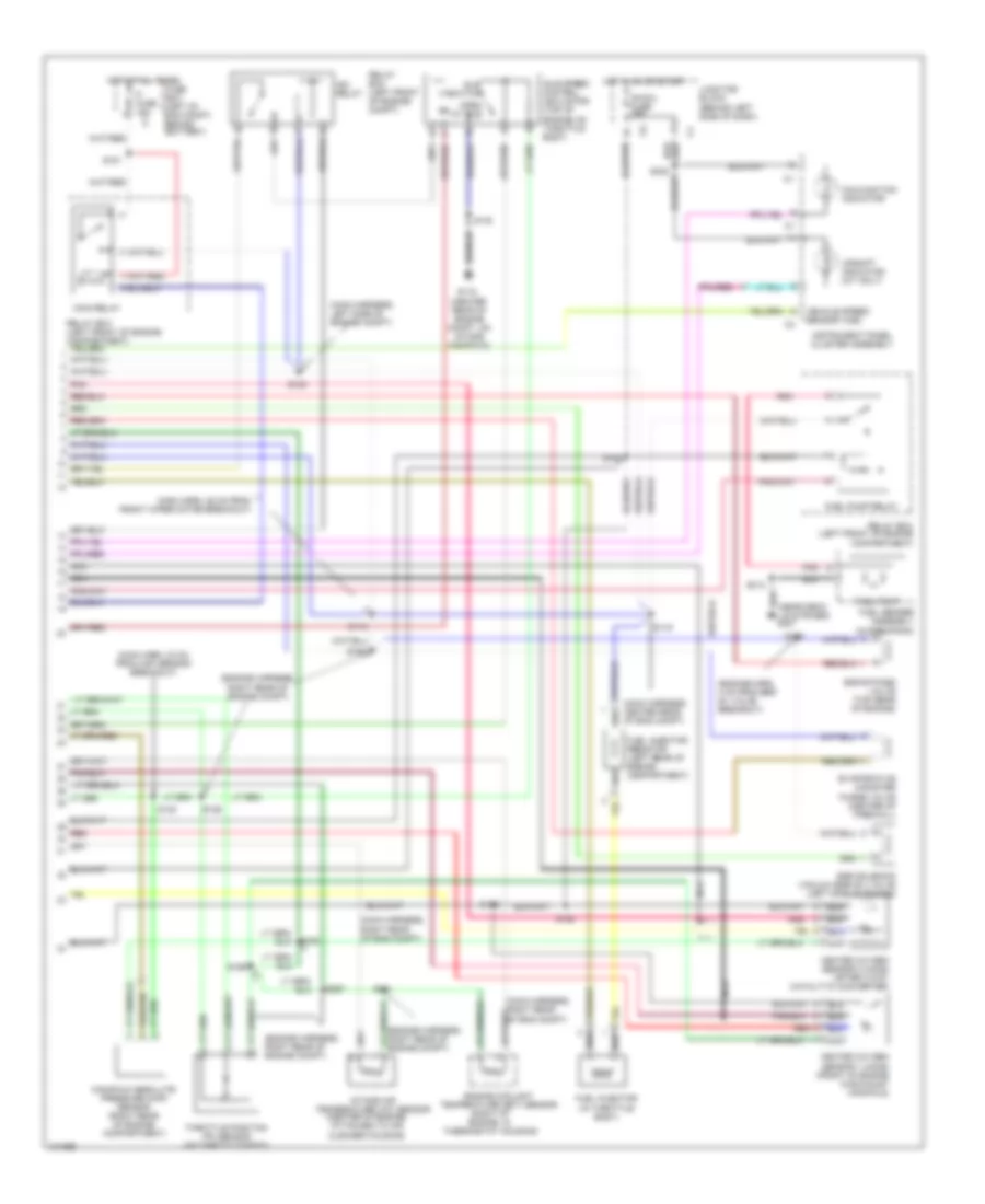
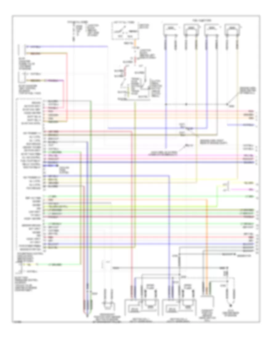
1.3L (VIN 2), Engine Performance Wiring Diagrams (1 of 3) for Chevrolet Metro 1998
List of elements for 1.3L (VIN 2), Engine Performance Wiring Diagrams (1 of 3) for Chevrolet Metro 1998:
- (engine harn, near center of firewall)
- (engine harn, right rear of engine compt)
- (main harn, 50 cm from wimer motor breakout)
- A/t
- Acc
- Camshaft position sensor (near ignition coil)
- Clutch pedal position switch (above clutch pedal)
- Cooling fans system
- Crankshaft position (ckp) sensor (bottom of engine, by crankshaft pulley)
- Dome fuse 15a
- Ecm ground
- Ect input
- Engine start sig
- Evap can cntrl
- Evap can vent
- Evap canister purge valve (top rear of engine)
- Evap canister vent control solenoid (top of fuel tank)
- Evap tank pres
- Evap tank pressure control solenoid vacuum valve (center of engine compartment)
- Fuel injectors
- Fuel pump relay
- G115 (center rear of engine)
- Generator
- Ground
- Ho2s1 heater
- Ho2s1 input
- Ho2s2 heater
- Hot at all times
- Iat input
- Ign pwr input
- Ign ref
- Ign trigger 1-4
- Ign trigger 2-3
- Ignition coil 1 (on cylinder head)
- Ignition coil 2 (on cylinder head)
- Ignition switch
- Inj 1 ctrl
- Inj 2 ctrl
- Inj 3 ctrl
- Inj 4 ctrl
- Junction block (behind left side of dash)
- Junction block (behind left side of dash)
- Lock
- M/t
- Map input
- Memory power
- Mil ind control
- Nca
- Pcm ground
- Pnk
- Powertrain control module (pcm) (behind right side of dash)
- Pwr steer press
- Rad fan relay
- Red
- Ref voltage
- Relay control
- Run
- S119
- S130
- S159
- S160
- S161
- S165
- S248
- S262
- S263
- Sensor ground
- Shift sol a
- Shift sol b
- Solid state
- Spark plugs
- Start
- Tp input
- Trans- axle range switch (on trans- axle)
- Vss
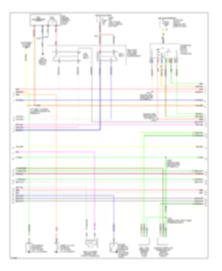
1.3L (VIN 2), Engine Performance Wiring Diagrams (2 of 3) for Chevrolet Metro 1998
List of elements for 1.3L (VIN 2), Engine Performance Wiring Diagrams (2 of 3) for Chevrolet Metro 1998:
- (engine harn, near center of firewall)
- (i/p harn, 3 cm from cluster connector breakout)
- (left of eng compt, behind battery)
- 2nd brake solenoid (attached to valve body)
- Back fuse 15a
- Direct clutch solenoid (attached to valve body)
- Fi fuse 15a c1
- Fuel level sensor
- Fuel pump
- Fuel pump relay
- Fuel sender assembly (in fuel tank)
- Fuel tank pressure sensor (in fuel tank)
- Fuse box
- G407 (center rear of trunk)
- Hot at all times
- Hot in on or start
- Instrument cluster system
- Junction block (behind left side of dash)
- Main relay
- Manifold absolute pressure (map) sensor (on intake plenum)
- N d
- Pnk
- Power steering pressure switch (on power steering pump)
- Red
- Relay box (left side of engine compartment)
- S129 (engine harn, right rear of engine compt)
- S151
- S154
- S158
- S226
- S259
- S315
- Transaxle range switch (top of transaxle)
- Vehicle speed sensor (vss) (top of transaxle)
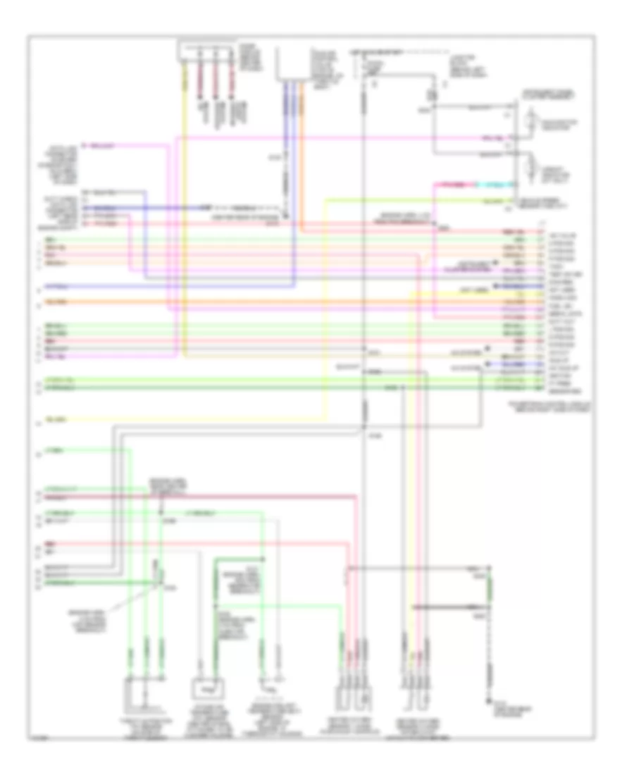
1.3L (VIN 2), Engine Performance Wiring Diagrams (3 of 3) for Chevrolet Metro 1998
List of elements for 1.3L (VIN 2), Engine Performance Wiring Diagrams (3 of 3) for Chevrolet Metro 1998:
- (center rear of engine) g115
- (engine harn, 4 cm from pcm breakout)
- (engine harn, 8 cm from map sensor breakout)
- (engine harn, near center of firewall)
- (not used)
- 2 pos sig
- A/c cut
- A/c idle up
- A/c system
- D pos sig
- Data link connector on board diagnostics ii (dlc-obdii) (left side of dash)
- Defogger system
- Diag req
- Diode module (behind center of dash)
- Duty check data link connector (left rear side of engine compt)
- Duty out
- Engine coolant temperature (ect) sensor (left side of engine, in thermostat housing)
- Ft pres
- Fuel lev
- G115 (center rear of engine)
- Heated oxygen sensor 1 (ho2s) (in exhaust manifold)
- Heated oxygen sensor 2 (ho2s) (after 3-way catalytic converter)
- Ho2s 2 sig
- Hot in on or start
- Iac valve
- Idle air control valve (top of engine, on throtle body)
- Idle up
- Ig-coil fuse 15a
- Ignition
- Instrument cluster system
- Instrument panel cluster assembly
- Intake air temperature (iat) sensor (center of eng, attached to air cleaner housing)
- Interior
- Junction block (behind left side of dash)
- L pos sig
- Lights system
- Malfunction indicator
- N pos sig
- Nca
- Not used
- P pos sig
- Pnk
- Powertrain control module (behind right side of dash)
- R pos sig
- Red
- S101
- S126
- S130
- S131 (engine harn, 9cm from generator breakout)
- S152
- S153
- S156
- S163 (engine harn, 2 cm from injector breakout)
- S164
- S167
- S242
- S248
- S261
- S263
- Sensor gnd
- Serial data
- Tach
- Test sw sig
- Throttle position (tp) sensor (on side of throttle body)
- Upshift indicator (m/t only)
- Vehicle speed sensor (vss) (m/t)