ENGINE PERFORMANCE
4.3L
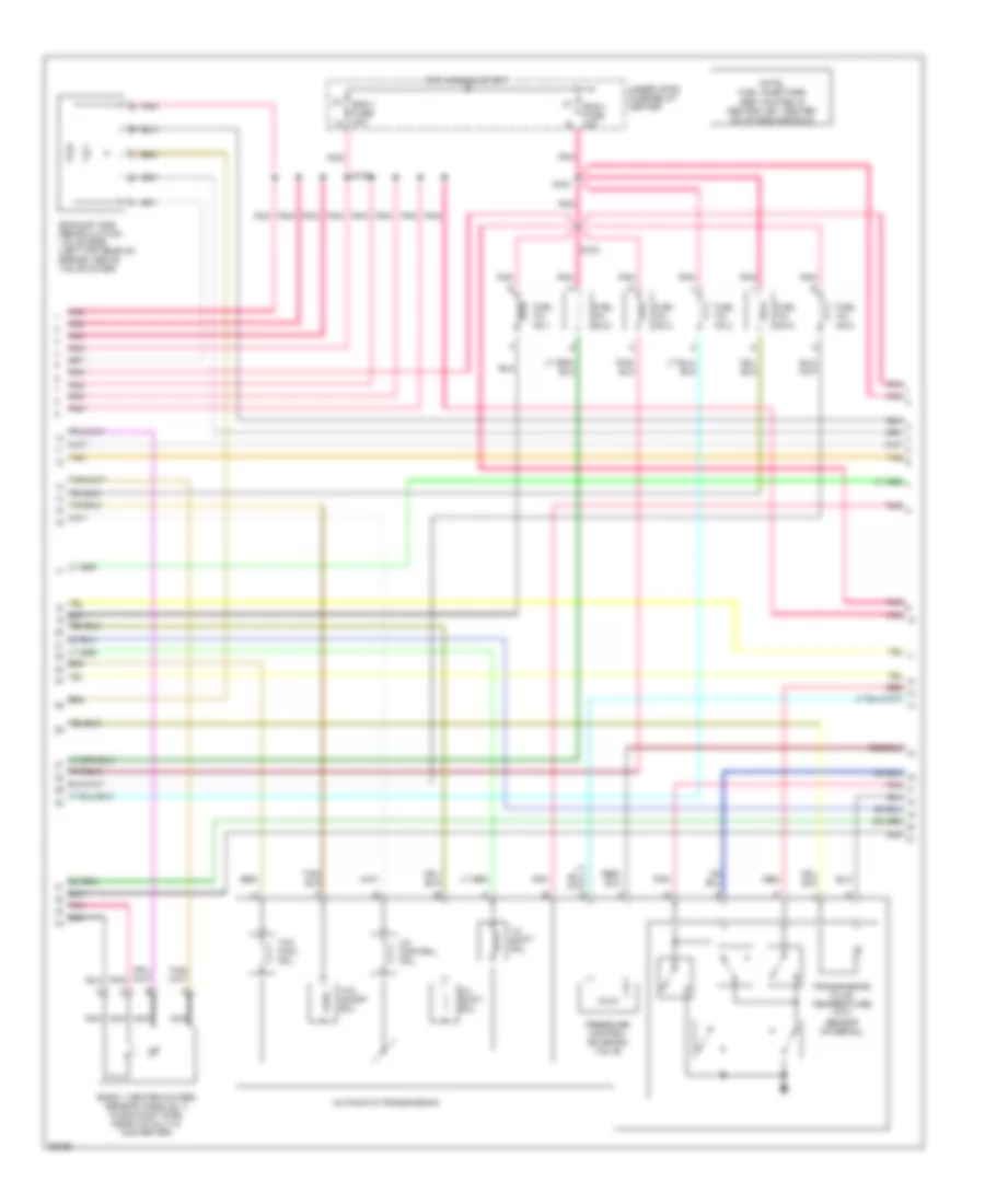
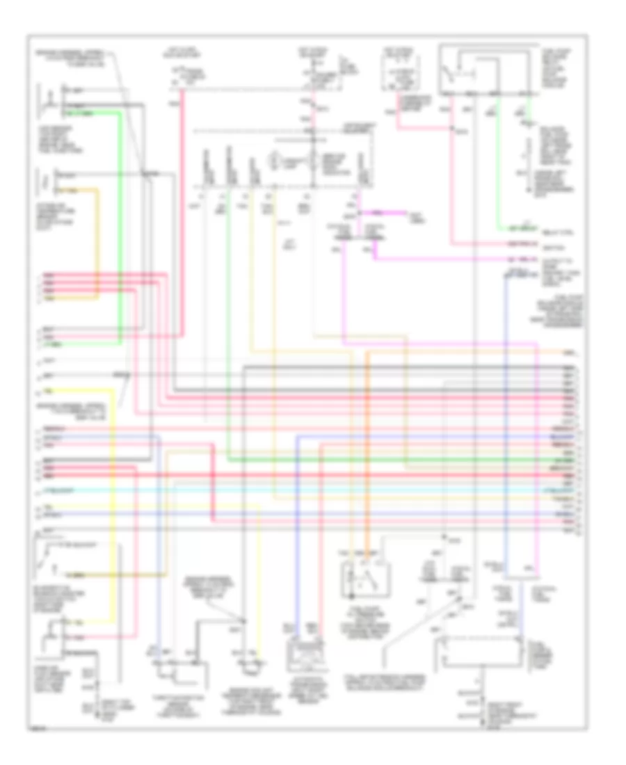
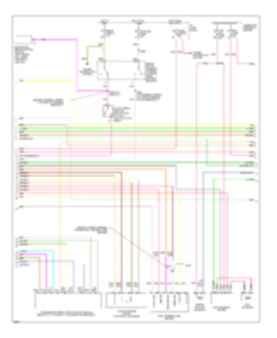
4.3L (VIN W), Engine Performance Wiring Diagrams (1 of 4) for Chevrolet Pickup C2500 1997

List of elements for 4.3L (VIN W), Engine Performance Wiring Diagrams (1 of 4) for Chevrolet Pickup C2500 1997:
- (a/t) s162 (m/t) s147
- (attached to right rear of throttle body)
- (left front of electronic brake control module) evaporative emissions canister vent (evap)
- (lower right front portion of engine block, near crankshaft) crankshaft position sensor
- (right side of engine) evaporative emissions (evap) canister purge valve
- (right top of cyl head) g120
- 1-2 shift sol. ctrl
- 2-3 shift sol. ctrl
- 3-2 ctrl sol. ctrl
- A/c comp rly ctrl
- A/c compressor enable relay
- Bank 1 heated oxygen sensor (ho2s) no.1 (in exhaust pipe, near catalytic converter)
- Bank 2 heated oxygen sensor (ho2s) no.1 (in exhaust pipe, near catalytic converter)
- Bank 2 heated oxygen sensor (ho2s) no.2 (in exhaust pipe, near catalytic converter)
- Cam posit sens rtn
- Cam posit sens sig
- Camshaft position sensor (in distributor)
- Coil
- Crank posit sens rtn
- Crank posit sens sig
- Ect sens input
- Egr posit input
- Evap
- Evap sol purge ctrl
- G120 (right front of engine block)
- Ground
- Hall effect sensor
- Iat sens sig
- Idle air control (iac) valve motor
- Idle air ctrl (iac) a hi
- Idle air ctrl (iac) b lo
- Ign feed
- Inj no.1 ctrl
- Inj no.2 ctrl
- Inj no.3 ctrl
- Inj no.4 ctrl
- Inj no.5 ctrl
- Inj no.6 ctrl
- Knock sens sig
- Knock sensor (forward of starter, on engine block)
- Left sens hi
- Left sens lo
- Map sens input
- Mass air flow sens sig
- Nca
- Pnk
- Post-catalyst sens hi
- Post-catalyst sens lo
- Power
- Pre-catalyst sens hi
- Pre-catalyst sens lo
- Purge valve
- Right sens hi
- Right sens lo
- S103
- S148
- S149
- Sens rtn
- Sens sig
- Sensor ground
- Tan
- Tcc on/off sol. ctrl
- Tcc pwm sol ctrl
- Throttle posit sens
- Trans temp sens sig
- Underhood fuse-relay center (left rear of engine compartment, on fender)
- Vcm ground
- Vehicle control module (vcm) (in engine compartment, near brake pressure modulator valve (bpmv), at left front wheelhouse)
- Vehicle spd sense sig
- Vehicle speed sensor (left rear side of transmission) (left side of transfer case-w/4wd)
- Vss rtn
- Vss signal
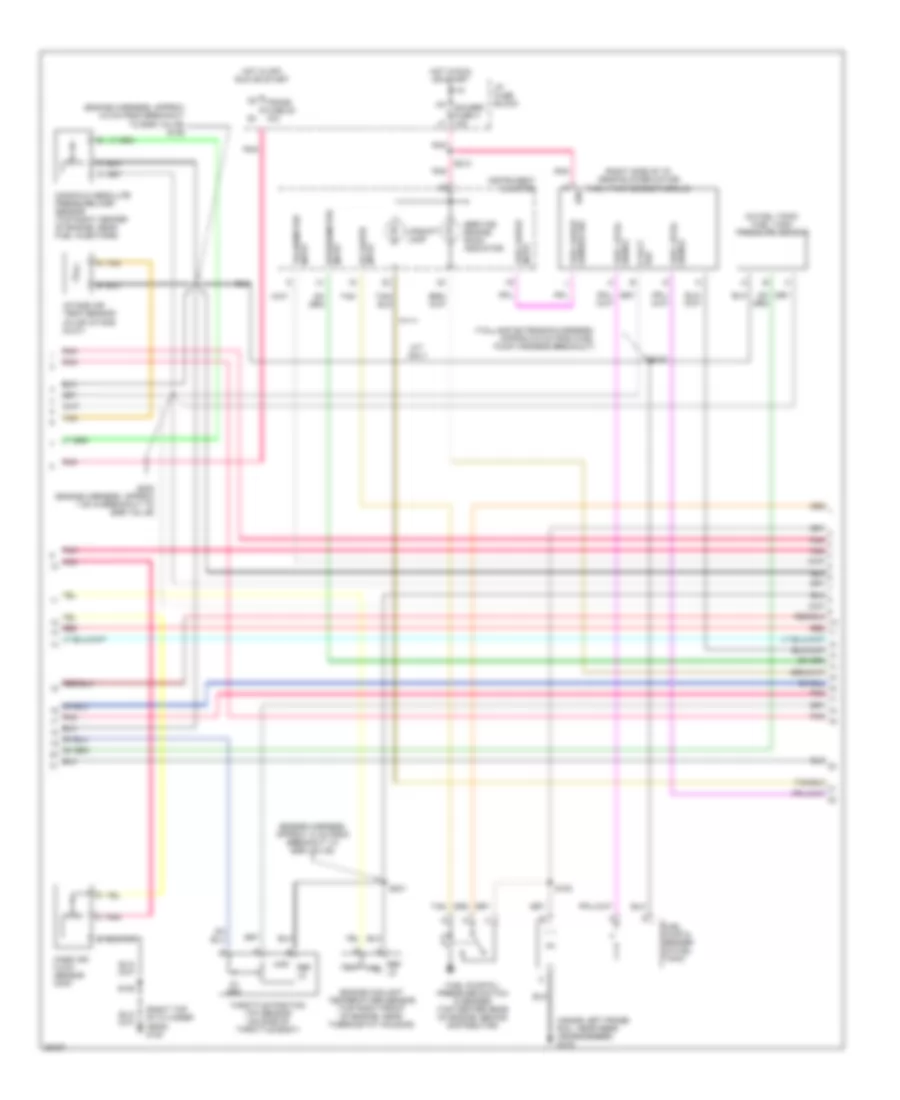
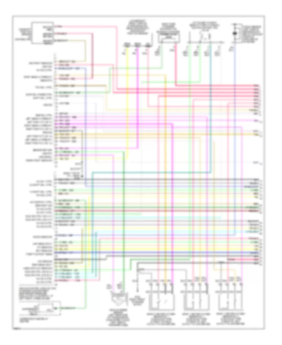
4.3L (VIN W), Engine Performance Wiring Diagrams (2 of 4) for Chevrolet Pickup C2500 1997
List of elements for 4.3L (VIN W), Engine Performance Wiring Diagrams (2 of 4) for Chevrolet Pickup C2500 1997:
- 1-2 shift sol.
- 2-3 shift sol.
- 3-2 control sol.
- Automatic transmission
- Bank 1 heated oxygen sensor (ho2s) no. 2 (in exhaust pipe, near catalytic converter)
- Ecm-1 fuse 20a
- Eng 1 fuse 20a
- Exhaust gas recirculation valve (egr) (left top rear of engine, above valve cover)
- Fuel inj. no.1
- Fuel inj. no.2
- Fuel inj. no.3
- Fuel inj. no.4
- Fuel inj. no.5
- Fuel inj. no.6
- Hot in run & start
- Nca
- Note: fuel injectors are located in central sfi, center of intake manifold
- Pnk
- Pnk pnk
- Pressure control solenoid valve
- Red
- S104
- S108
- S161
- Tan
- Tcc on/off sol.
- Tcc pwm sol.
- Transmission fluid temperature (tft) sensor (internal)
- Under hood fuse-relay center
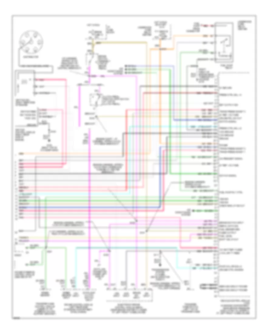
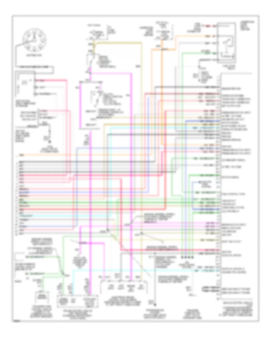
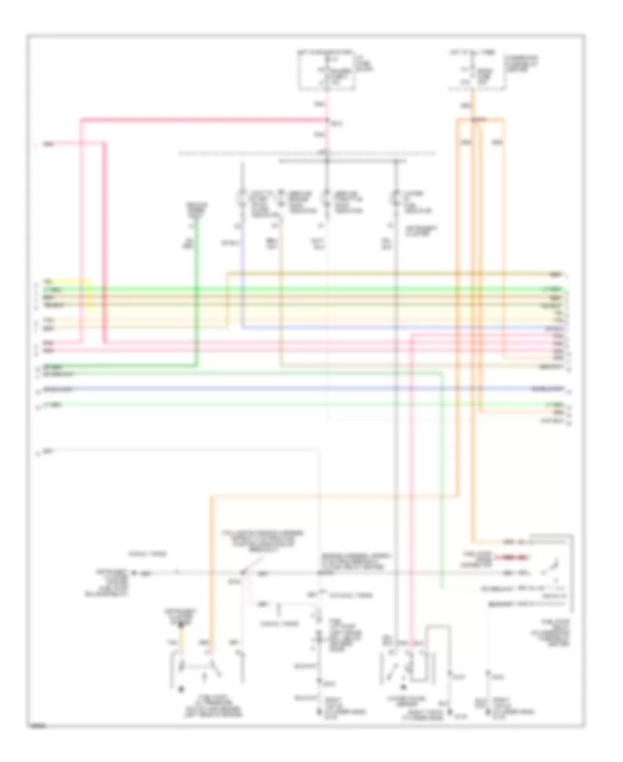
4.3L (VIN W), Engine Performance Wiring Diagrams (3 of 4) for Chevrolet Pickup C2500 1997
List of elements for 4.3L (VIN W), Engine Performance Wiring Diagrams (3 of 4) for Chevrolet Pickup C2500 1997:
- (engine harness, approx 13 cm from breakout to egr valve)
- (engine harness, approx 4.5 cm from breakout to egr valve) s106
- (in fuel tank) fuel tank pressure sensor
- (inside left frame- rail, near rear crossmember) g416
- (right side of i/p, near blower motor) fuel tank sender module
- (right top of cylinder head) g120
- (taillamp extension harness, approx 6.5 cm from fuel pump harness breakout)
- 5v ref
- Engine coolant temperature sensor (top right front of engine, near thermostat housing)
- Fuel gauge sensor sig
- Fuel level signal
- Fuel pump & sender (in fuel tank)
- Fuel pump/oil pressure switch & sender (top center rear of engine, behind distributor)
- Gauges fuse 4 10a
- Hot in off, run or start
- Hot in run or start
- I/p fuse block
- Ign
- Input fuel gauge
- Input oil gauge
- Input tachometer
- Instrument cluster
- Intake air temp sensor (in air intake duct)
- M/t only
- Manifold absolute pressure (map) sensor (top right center of engine, near fuel injectors)
- Map
- Mass air flow sensor (maf)
- Pnk
- Red
- Ref 5 volt
- Ref lo
- S100
- S180
- S213
- S231
- S232 (engine harness, approx 7 cm in breakout to egr valve)
- S430
- Service engine soon indicator
- Signal fuel level
- Speedometer input
- Tan
- Tan a
- Temp
- Throttle position (tp) sensor (on side of throttle body)
- Trans fuse 20 10a
- Upshift lamp
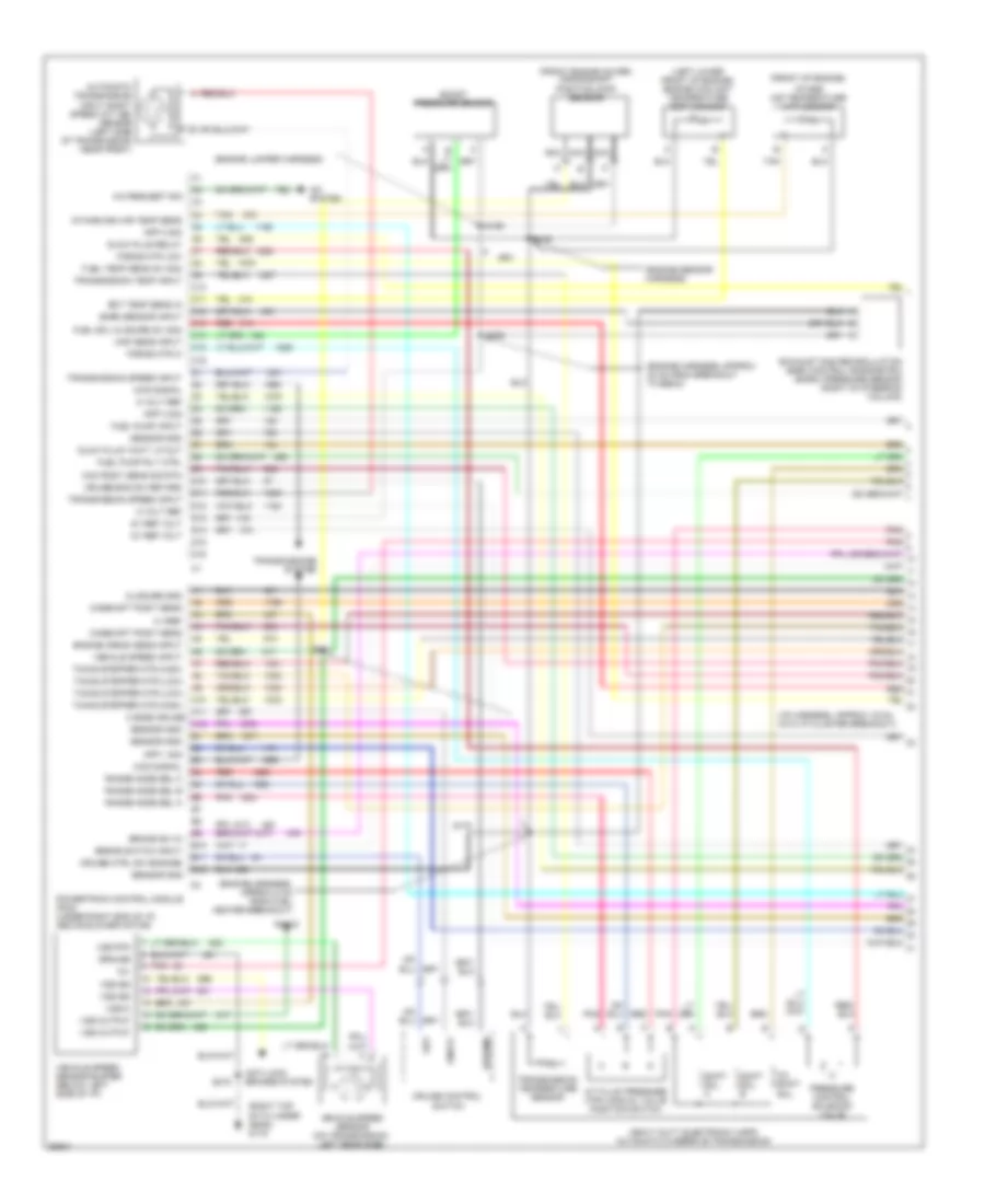
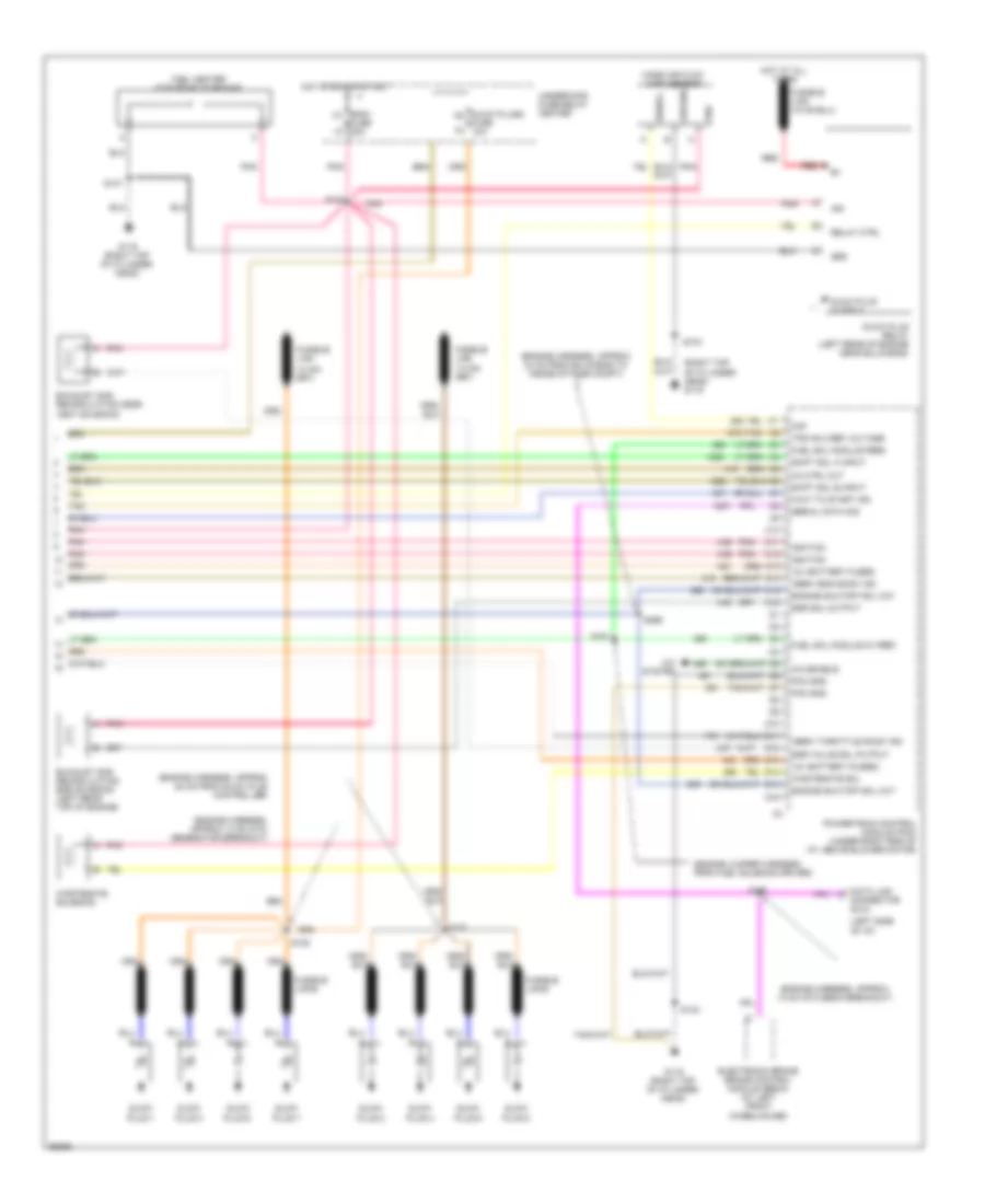
4.3L (VIN W), Engine Performance Wiring Diagrams (4 of 4) for Chevrolet Pickup C2500 1997
List of elements for 4.3L (VIN W), Engine Performance Wiring Diagrams (4 of 4) for Chevrolet Pickup C2500 1997:
- (engine compt., i/p harness, approx 6.5 cm into ebcm breakout)
- (engine harness, approx 13 cm into ebcm breakout)
- (engine harness, approx 4 cm from breakout to taillamp harness)
- (engine harness, approx 6.5 cm from underhood fuse-relay center breakout)
- (engine harness, approx 6.5 cm into ebcm breakout)
- (i/p harness, approx 20 cm from i/p cluster breakout)
- (i/p harness, approx 20 cm from right of heater and a/c control breakout)
- (or
- (right front of engine near thermostat housing) g119
- 12v battery fused
- 20a
- 4 whl dr tt feed
- 4wd input
- 5v ref. voltage
- 5v return
- A pnk
- A/c request signal
- A/t
- A/t only
- Air conditioning system
- Brake sw input
- Brake switch assembly (top of brake pedal)
- Brake switch input
- Check eng lp ind out
- Clutch pedal position (cpp) switch (at top of clutch pedal)
- Cruise control module (left rear side of engine compartment, on bulkhead)
- Cruise ctrl sig-eng
- Cruise pdl sw out
- Data link connector (under left side of i/p)
- Distributor
- Ecm b f11
- Electronic brake control module (ebcm) (near brake master cylinder, at left front wheelhouse)
- Est output sig
- Four whl dr sig lo
- Fuel a pump prime connector
- Fuel level
- Fuel pump relay
- Fuel pump rly ctrl
- Fuel sender grd
- Fused output
- G120 (right top of cylinder head)
- Ground
- High voltage coil wire
- Hot in run
- Hot in run or start
- I/p fuse block
- Ign input
- Ign timing sig.
- Ignition coil (right rear side of engine)
- Ignition control module (right rear side of engine)
- Ignition feed
- M/t
- M4 brake fuse 18 10a n3
- Mini fuse g12
- Pnk
- Power
- Power steering control module (center of i/p)
- Press ctrl sol lo
- Press ctrl sol. hi
- Radio
- Red
- S101
- S103
- S111
- S150
- S151
- S152
- S153
- S180
- S221
- S222
- Serial data sig
- Service circuit power
- Shift ind lp out
- Speed sensor
- Speed sensor input
- Stoplamp/ clutch switch input
- Switch signal
- Tach. sig.
- Trans press sig-bit 1
- Trans press sig-bit 2
- Trans press sig-bit 3
- Transfer case control module (under i/p, on steering column support bracket)
- Transfer case switch (left top of transfer case)
- Transmissions system (4 wheel drive indicator circuit)
- Underhood fuse- relay center
- Vcm ground
- Vcm input
- Vehicle control module (vcm) (in engine compartment, near brake pressure modulator valve (bpmv), at left front wheelhouse)
- Vss input
- Vss sig
5.0L
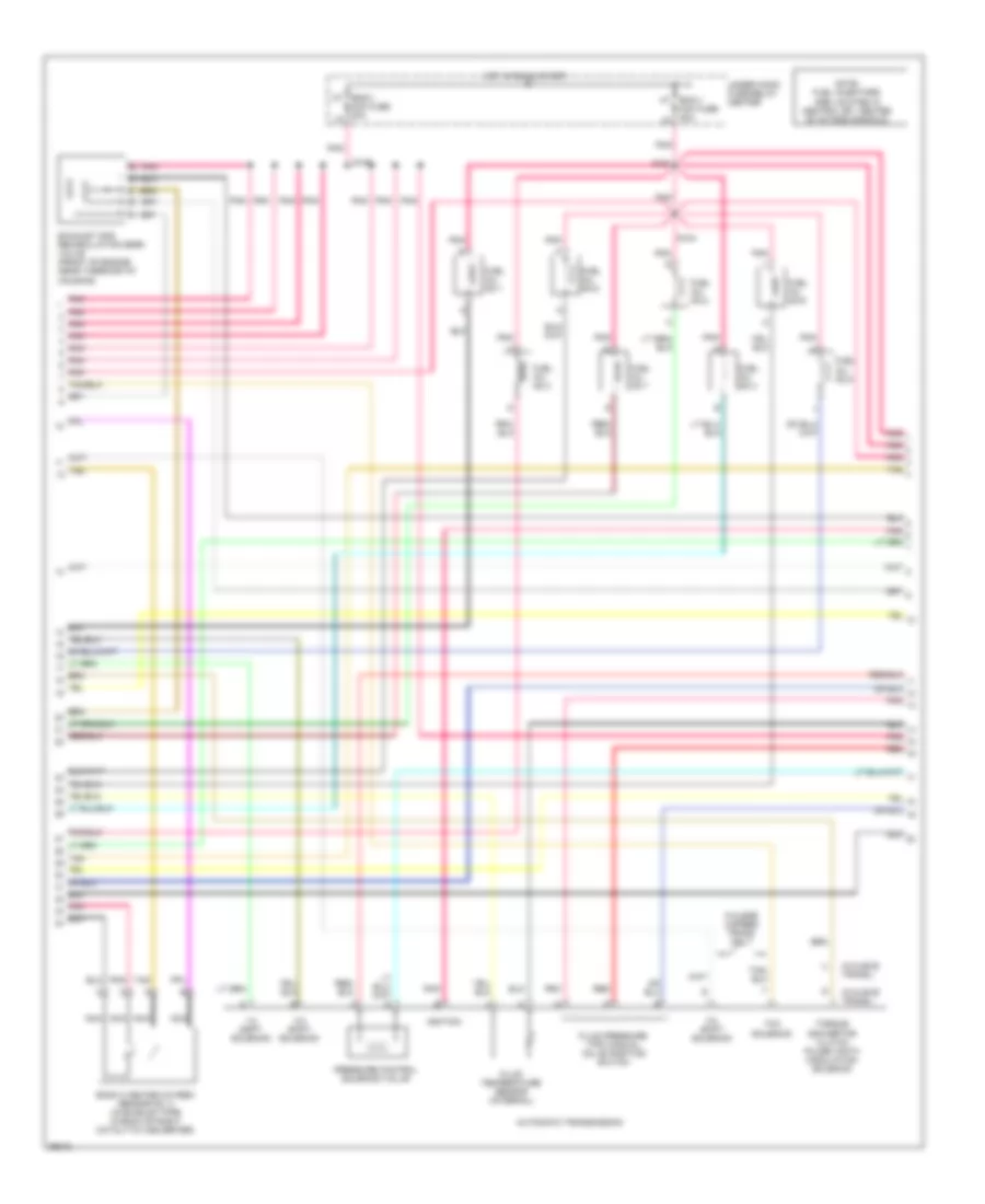
5.0L (VIN M), Engine Performance Wiring Diagrams (1 of 4) for Chevrolet Pickup C2500 1997
List of elements for 5.0L (VIN M), Engine Performance Wiring Diagrams (1 of 4) for Chevrolet Pickup C2500 1997:
- (attached to right rear of throttle body) idle air control (iac) valve
- (lower right front portion of engine block, near crankshaft) crankshaft position sensor
- (right side of engine) evaporative emission canister purge valve
- (right top of cyl. head) g120
- 1-2 shift sol. ctrl
- 2-3 shift sol. ctrl
- A/c comp rly ctrl
- A/c compressor clutch relay
- Bank 1 heated oxygen sensor no. 1 (in exhaust pipe in front of left catalytic converter)
- Bank 1 heated oxygen sensor no. 2 (in exhaust pipe in back of left catalytic converter)
- Bank 2 heated oxygen sensor no. 1 (in exhaust pipe in front of right catalytic converter)
- Cam posit sens sig
- Camshaft position sensor (in distributor)
- Coil
- Crank posit sens sig
- Ect sens sig
- Egr posit sig
- Egr sol ctrl
- Evap sol purge ctrl
- G120 (right front of engine block)
- Ground
- Iat sens sig
- Idle air ctrl (iac) a hi
- Idle air ctrl (iac) b lo
- Ign feed
- Ignition
- Inj no.1 ctrl
- Inj no.2 ctrl
- Inj no.3 ctrl
- Inj no.4 ctrl
- Inj no.5 ctrl
- Inj no.6 ctrl
- Inj no.7 ctrl
- Inj no.8 ctrl
- Knock sens sig
- Knock sensor (left side of engine block, below exhaust manifold, forward of starter)
- Left post ctylst hi
- Left post-ctylst lo
- Left sens hi (precat)
- Left sens lo (precat)
- Map sens input
- Mass air flow sens sig
- Nca
- Pnk
- Pnk c ignition feed
- Right post-ctlyst hi
- Right post-ctlyst lo
- Right sens hi (precat)
- Right sens lo (precat)
- S103
- S148
- S149
- S162
- Sens rtn
- Sens sig
- Sensor return
- Shift sol. ctrl
- Tan
- Tcc sol ctrl
- Tcc sol. ctrl
- Temp sens input
- Throttle posit sens
- Underhood fuse-relay center
- Vcm ground
- Vehicle control module (vcm) (in engine compartment, near brake pressure modulator valve (bpmv), at left front wheelhouse)
- Vehicle speed sensor (left rear side of transmission) (if equipped w/4wd) (left side of transfer case)
- Vss rtn
- Vss sig
- Vss signal
5.0L (VIN M), Engine Performance Wiring Diagrams (2 of 4) for Chevrolet Pickup C2500 1997
List of elements for 5.0L (VIN M), Engine Performance Wiring Diagrams (2 of 4) for Chevrolet Pickup C2500 1997:
- (w/4l60-e trans.)
- (w/4l80-e trans.)
- 1-2 shift solenoid
- 2-3 shift solenoid
- 3-2 shift solenoid
- Automatic transmission
- Bank 2 heated oxygen sensor no. 2 (in exhaust pipe in back of right catalytic converter)
- Ecm-1 mini fuse 20a
- Eng-1 k7
- Exhaust gas recirculation (egr) valve (front of engine near thermostat housing)
- Fluid pressure (tfp) manual valve position switch
- Fluid temperature sensor (internal)
- Fuel inj. no.1
- Fuel inj. no.2
- Fuel inj. no.3
- Fuel inj. no.4
- Fuel inj. no.5
- Fuel inj. no.6
- Fuel inj. no.7
- Fuel inj. no.8
- Hot in run & start
- Ignition
- Mini fuse 20a l8
- Nca
- Note: fuel injectors are located in central sfi, center of intake manifold
- Pnk
- Pnk pnk pnk tan
- Pressure control solenoid valve
- Red
- S104
- S108
- S161
- Tan
- Tcc solenoid
- Torque convertor clutch pulse width modulation solenoid
- Under hood fuse-relay center
- W/4l60e 4-speed trans. only
5.0L (VIN M), Engine Performance Wiring Diagrams (3 of 4) for Chevrolet Pickup C2500 1997
List of elements for 5.0L (VIN M), Engine Performance Wiring Diagrams (3 of 4) for Chevrolet Pickup C2500 1997:
- (engine harness, approx 13 cm from breakout to egr valve)
- (engine harness, approx 4.5 cm from breakout to egr valve)
- (engine harness, approx 7 cm in breakout to egr valve)
- (inside left frame rail, near rear crossmember) g415
- (not used)
- (right front of engine, near thermostat housing) g119
- (right top of cylinder head) g120
- (taillamp extension harness, approx 10 cm from fuel pump balance module breakout)
- Automatic transmission input shaft speed (a/t iss) sensor
- Balance fuel pump (on inside left frame rail near front of rear tank)
- Engine coolant temperature sensor (top right front of engine, near thermostat housing)
- Evaporative emission canister vacuum switch (right side of engine)
- Fuel pump & sender (in fuel tank)
- Fuel pump balance module (inside left side of frame rail near transmission crossmember)
- Fuel pump balance relay (on fuel pump balance module)
- Fuel pump/ oil pressure switch (top center rear of engine, behind distributor)
- Gauges fuse 4 10a
- Hot in off, run or start
- Hot in run or start
- Hot in run, or start
- I/p fuse block
- Ign e f7
- Ignition
- Input fuel gauge
- Input oil gauge
- Input tachometer
- Instrument cluster
- Intake air temperature sensor (in air intake duct)
- M/t only
- Map sensor (top right center of engine, near fuel injectors)
- Mass air flow sensor (air intake duct near air filter)
- Mini fuse 10a
- Output to gage
- Pnk
- Pnk a
- Pnk pnk tan
- Primary tank fuel level signal
- Relay ctrl
- S100
- S103
- S106
- S180
- S213
- S231
- S232
- S276
- S315
- S318
- Service engine soon indicator
- Speedometer input
- Tan
- Tan a
- Throttle position sensor (on side of throttle body)
- Trans fuse 20 10a
- Underhood fuse-relay center pnk
- Upshift lamp
- W/dual fuel tanks
- W/o dual fuel tanks
- W/o dual fuel tanks
5.0L (VIN M), Engine Performance Wiring Diagrams (4 of 4) for Chevrolet Pickup C2500 1997
List of elements for 5.0L (VIN M), Engine Performance Wiring Diagrams (4 of 4) for Chevrolet Pickup C2500 1997:
- (engine compt., i/p harness, approx 6.5 cm into ebcm breakout)
- (engine harness, approx 13 cm into ebcm breakout)
- (engine harness, approx 38.5 cm from underhood fuse/relay center)
- (engine harness, approx 6.5 cm from underhood fuse-relay center breakout)
- (engine harness, approx 6.5 cm into ebcm breakout)
- (i/p harness, approx 20 cm from i/p cluster breakout)
- (or
- (right top of cylinder head) g120
- 20a
- 4wd input
- 5v ref. voltage
- A/c request signal
- A/t
- Air conditioning system
- Aux fan relay
- Brake sw input
- Brake switch assembly (top of brake pedal)
- Brake switch input
- Check eng lp ctrl
- Clutch pedal position switch (at top of clutch pedal)
- Cooling fans system
- Cruise control module (left rear side of engine compartment, on bulkhead)
- Cruise ctrl sig eng
- Cruise pdl sw out
- Data link connector (under left side of i/p)
- Distributor
- Ecm-b f11
- Electronic brake control module (ebcm) (near brake master cylinder, at left front wheelhouse)
- Est output sig
- Evap purge vac sw
- Force motor feed
- Force motor return
- Four whl dr sig
- Four whl dr sig lo
- Fuel a pump prime connector
- Fuel pump relay
- Fuel pump rly ctrl
- G120 (right top of cylinder head)
- Ground
- High voltage coil wire
- Hot at all times
- Hot in run
- I/p fuse block
- Ign coil out
- Ign input
- Ign timing sig.
- Ignition
- Ignition coil (right rear side of engine)
- Ignition coil driver (right rear side of engine)
- Ignition feed
- M/t
- M4 brake fuse 18 10a n3
- Mini fuse g12
- Pnk
- Pnk a
- Power steering control module (center of i/p)
- Pressure switch input
- Radio
- Red
- S101
- S103
- S111 (engine harness, approx 4 cm from breakout to taillamp harness)
- S150
- S151
- S152
- S153
- S163
- S221
- Sensor ground
- Sensor return
- Serial data sig
- Service circuit power
- Shift ind lp out
- Speed sensor
- Speed sensor input
- Stoplamp/ clutch switch input
- Switch signal
- Trans input speed rtn
- Trans input speed sig
- Transfer case control module (under i/p, on steering column support bracket)
- Transfer case switch (left top of transfer case)
- Transmissions system (four wheel drive indicator circuit
- Underhood fuse- relay center
- Vcm ground
- Vcm sig
- Vehicle control module (vcm) (in engine compartment, near brake pressure modulator valve (bpmv), at left front wheelhouse)
- Vss input
- Vss sig out
5.7L
5.7L (VIN R), Engine Performance Wiring Diagrams (1 of 4) for Chevrolet Pickup C2500 1997
List of elements for 5.7L (VIN R), Engine Performance Wiring Diagrams (1 of 4) for Chevrolet Pickup C2500 1997:
- (attached to right rear of throttle body) idle air control (iac) valve
- (lower right front portion of engine block, near crankshaft) crankshaft position sensor
- (right side of engine) evaporative emission canister purge valve
- (right top of cyl. head) g120
- 1-2 shift sol. ctrl
- 2-3 shift sol. ctrl
- A/c comp rly ctrl
- A/c compressor clutch relay
- Bank 1 heated oxygen sensor no. 1 (in exhaust pipe in front of left catalytic converter)
- Bank 1 heated oxygen sensor no. 2 (in exhaust pipe in back of left catalytic converter)
- Bank 2 heated oxygen sensor no. 1 (in exhaust pipe in front of right catalytic converter)
- Cam posit sens sig
- Camshaft position sensor (in distributor)
- Coil
- Crank posit sens sig
- Ect sens sig
- Egr posit sig
- Egr sol ctrl
- Evap sol purge ctrl
- G120 (right front of engine block)
- Ground
- Iat sens sig
- Idle air ctrl (iac) a hi
- Idle air ctrl (iac) b lo
- Ign feed
- Ignition
- Inj no.1 ctrl
- Inj no.2 ctrl
- Inj no.3 ctrl
- Inj no.4 ctrl
- Inj no.5 ctrl
- Inj no.6 ctrl
- Inj no.7 ctrl
- Inj no.8 ctrl
- Knock sens sig
- Knock sensor (left side of engine block, below exhaust manifold, forward of starter)
- Left post ctylst hi
- Left post-ctylst lo
- Left sens hi (precat)
- Left sens lo (precat)
- Map sens input
- Mass air flow sens sig
- Nca
- Pnk
- Pnk c ignition feed
- Right post-ctlyst hi
- Right post-ctlyst lo
- Right sens hi (precat)
- Right sens lo (precat)
- S103
- S148
- S149
- S162
- Sens rtn
- Sens sig
- Sensor return
- Shift sol. ctrl
- Tan
- Tcc sol ctrl
- Tcc sol. ctrl
- Temp sens input
- Throttle posit sens
- Underhood fuse-relay center
- Vcm ground
- Vehicle control module (vcm) (in engine compartment, near brake pressure modulator valve (bpmv), at left front wheelhouse)
- Vehicle speed sensor (left rear side of transmission) (if equipped w/4wd) (left side of transfer case)
- Vss rtn
- Vss sig
- Vss signal
5.7L (VIN R), Engine Performance Wiring Diagrams (2 of 4) for Chevrolet Pickup C2500 1997
List of elements for 5.7L (VIN R), Engine Performance Wiring Diagrams (2 of 4) for Chevrolet Pickup C2500 1997:
- (w/4l60-e trans.)
- (w/4l80-e trans.)
- 1-2 shift solenoid
- 2-3 shift solenoid
- 3-2 shift solenoid
- Automatic transmission
- Bank 2 heated oxygen sensor no. 2 (in exhaust pipe in back of right catalytic converter)
- Ecm-1 mini fuse 20a
- Eng-1 k7
- Exhaust gas recirculation (egr) valve (front of engine near thermostat housing)
- Fluid pressure (tfp) manual valve position switch
- Fluid temperature sensor (internal)
- Fuel inj. no.1
- Fuel inj. no.2
- Fuel inj. no.3
- Fuel inj. no.4
- Fuel inj. no.5
- Fuel inj. no.6
- Fuel inj. no.7
- Fuel inj. no.8
- Hot in run & start
- Ignition
- Mini fuse 20a l8
- Nca
- Note: fuel injectors are located in central sfi, center of intake manifold
- Pnk
- Pnk pnk pnk tan
- Pressure control solenoid valve
- Red
- S104
- S108
- S161
- Tan
- Tcc solenoid
- Torque convertor clutch pulse width modulation solenoid
- Under hood fuse-relay center
- W/4l60e 4-speed trans. only
5.7L (VIN R), Engine Performance Wiring Diagrams (3 of 4) for Chevrolet Pickup C2500 1997
List of elements for 5.7L (VIN R), Engine Performance Wiring Diagrams (3 of 4) for Chevrolet Pickup C2500 1997:
- (engine harness, approx 13 cm from breakout to egr valve)
- (engine harness, approx 4.5 cm from breakout to egr valve)
- (engine harness, approx 7 cm in breakout to egr valve)
- (inside left frame rail, near rear crossmember) g415
- (not used)
- (right front of engine, near thermostat housing) g119
- (right top of cylinder head) g120
- (taillamp extension harness, approx 10 cm from fuel pump balance module breakout)
- Automatic transmission input shaft speed (a/t iss) sensor
- Balance fuel pump (on inside left frame rail near front of rear tank)
- Engine coolant temperature sensor (top right front of engine, near thermostat housing)
- Evaporative emission canister vacuum switch (right side of engine)
- Fuel pump & sender (in fuel tank)
- Fuel pump balance module (inside left side of frame rail near transmission crossmember)
- Fuel pump balance relay (on fuel pump balance module)
- Fuel pump/ oil pressure switch (top center rear of engine, behind distributor)
- Gauges fuse 4 10a
- Hot in off, run or start
- Hot in run or start
- Hot in run, or start
- I/p fuse block
- Ign e f7
- Ignition
- Input fuel gauge
- Input oil gauge
- Input tachometer
- Instrument cluster
- Intake air temperature sensor (in air intake duct)
- M/t only
- Map sensor (top right center of engine, near fuel injectors)
- Mass air flow sensor (air intake duct near air filter)
- Mini fuse 10a
- Output to gage
- Pnk
- Pnk a
- Pnk pnk tan
- Primary tank fuel level signal
- Relay ctrl
- S100
- S103
- S106
- S180
- S213
- S231
- S232
- S276
- S315
- S318
- Service engine soon indicator
- Speedometer input
- Tan
- Tan a
- Throttle position sensor (on side of throttle body)
- Trans fuse 20 10a
- Underhood fuse-relay center pnk
- Upshift lamp
- W/dual fuel tanks
- W/o dual fuel tanks
- W/o dual fuel tanks
5.7L (VIN R), Engine Performance Wiring Diagrams (4 of 4) for Chevrolet Pickup C2500 1997
List of elements for 5.7L (VIN R), Engine Performance Wiring Diagrams (4 of 4) for Chevrolet Pickup C2500 1997:
- (engine compt., i/p harness, approx 6.5 cm into ebcm breakout)
- (engine harness, approx 13 cm into ebcm breakout)
- (engine harness, approx 38.5 cm from underhood fuse/relay center)
- (engine harness, approx 6.5 cm from underhood fuse-relay center breakout)
- (engine harness, approx 6.5 cm into ebcm breakout)
- (i/p harness, approx 20 cm from i/p cluster breakout)
- (or
- (right top of cylinder head) g120
- 20a
- 4wd input
- 5v ref. voltage
- A/c request signal
- A/t
- Air conditioning system
- Aux fan relay
- Brake sw input
- Brake switch assembly (top of brake pedal)
- Brake switch input
- Check eng lp ctrl
- Clutch pedal position switch (at top of clutch pedal)
- Cooling fans system
- Cruise control module (left rear side of engine compartment, on bulkhead)
- Cruise ctrl sig eng
- Cruise pdl sw out
- Data link connector (under left side of i/p)
- Distributor
- Ecm-b f11
- Electronic brake control module (ebcm) (near brake master cylinder, at left front wheelhouse)
- Est output sig
- Evap purge vac sw
- Force motor feed
- Force motor return
- Four whl dr sig
- Four whl dr sig lo
- Fuel a pump prime connector
- Fuel pump relay
- Fuel pump rly ctrl
- G120 (right top of cylinder head)
- Ground
- High voltage coil wire
- Hot at all times
- Hot in run
- I/p fuse block
- Ign coil out
- Ign input
- Ign timing sig.
- Ignition
- Ignition coil (right rear side of engine)
- Ignition coil driver (right rear side of engine)
- Ignition feed
- M/t
- M4 brake fuse 18 10a n3
- Mini fuse g12
- Pnk
- Pnk a
- Power steering control module (center of i/p)
- Pressure switch input
- Radio
- Red
- S101
- S103
- S111 (engine harness, approx 4 cm from breakout to taillamp harness)
- S150
- S151
- S152
- S153
- S163
- S221
- Sensor ground
- Sensor return
- Serial data sig
- Service circuit power
- Shift ind lp out
- Speed sensor
- Speed sensor input
- Stoplamp/ clutch switch input
- Switch signal
- Trans input speed rtn
- Trans input speed sig
- Transfer case control module (under i/p, on steering column support bracket)
- Transfer case switch (left top of transfer case)
- Transmissions system (four wheel drive indicator circuit
- Underhood fuse- relay center
- Vcm ground
- Vcm sig
- Vehicle control module (vcm) (in engine compartment, near brake pressure modulator valve (bpmv), at left front wheelhouse)
- Vss input
- Vss sig out
6.5L
6.5L (VIN S), Engine Performance Wiring Diagrams (1 of 4) for Chevrolet Pickup C2500 1997
List of elements for 6.5L (VIN S), Engine Performance Wiring Diagrams (1 of 4) for Chevrolet Pickup C2500 1997:
- (engine harness, approx 43 cm from breakout to ebcm)
- (engine harness, approx 8 cm from fuel heater breakout)
- (engine jumper harness)
- (engine sensor harness)
- (front engine cover) crankshaft position (ckp) sensor)
- (front of engine)
- (i/p harness, approx 16 cm into i/p cluster breakout)
- (left lower front of engine) engine coolant temperature (ect) sensor
- (right top of cylinder head) g119
- 12v
- 3/2 shift sol.
- 4wd signal
- 5 volt ref
- 5 vref
- 5v ref volt
- A/c request sig
- A/c system
- A/t fluid pressure (tfp) manual valve position switch
- A10
- A11 3 mode cruise a12
- Anti-lock brakes system
- App 1 sig
- App 2 sig
- App 3 sig
- Automatic transmission input shaft speed (a/t iss) sensor (left side of transmission near front)
- B10
- B11
- B12
- Baro sensor input
- Boost pressure sensor
- Brake sw in
- Brake switch input
- C10
- C11
- C12
- C13
- C14
- C15
- C16
- Cam posit sens sig rtn
- Camshaft posit sens
- Closure gnd
- Cruise control
- Cruise ctrl sw engage
- Cruise eng sw retard
- D10
- D11
- D12
- D13
- D14
- D15
- D16
- Ect temp sens in
- Engine crank sens input
- Exhaust gas recirculation (egr) control/ barometric (baro) pressure sensor (right of steering column)
- Force mtr hi
- Force mtr low
- Fuel pump input
- Fuel pump rly ctrl
- Fuel sol closure (5v sig)
- Fuel temp sens (5v sig)
- Glow plug "wait" lp out
- Glow plug relay
- Ground
- Heavy duty electronic 4-spd automatic overdrive transmission
- Intake air temperature (iat) sensor
- Intake man air temp sens
- Map sens input
- Nca
- On/off
- Pnk
- Powertrain control module (pcm) (under right end of i/p, above blower motor)
- Pressure control solenoid valve
- Radio
- Range mode sel a
- Range mode sel b
- Range mode sel c
- Red
- Resume
- S140
- S170
- S199
- S211
- S215
- S230
- Sensor gnd
- Set
- Shift sol. a
- Shift sol. b
- Switch
- Tan
- Timing stepper mtr (high)
- Timing stepper mtr (low)
- Transmission speed input
- Transmission temp input
- Transmission temperature sensor
- Transmissions system
- Vehicle speed input
- Vehicle speed sensor (on transmission, left rear side)
- Vehicle speed sensor buffer (below left side of i/p)
- Vss hi
- Vss output
- Vss rtn
- Vss sig
6.5L (VIN S), Engine Performance Wiring Diagrams (2 of 4) for Chevrolet Pickup C2500 1997
List of elements for 6.5L (VIN S), Engine Performance Wiring Diagrams (2 of 4) for Chevrolet Pickup C2500 1997:
- (engine harness, approx 4 cm from i/p harness breakout)
- (engine jumper harness, toward fuel temperature sensor)
- 5 volt ref
- Accelerator pedal position (app) module (below i/p, attached to accelerator bracket)
- Brake switch assembly (at rear of brake pedal support bracket)
- Clutch pedal position (cpp) switch (m/t only) (top of clutch pedal)
- Cmp sig
- D2 trans fuse 20 20a e1
- D8 stop/haz fuse 1 20a c7
- Ecm h7
- Electronic brake control module (left frame rail, near center of vehicle)
- Engine shutoff solenoid
- Fuel f5
- Fuel solenoid
- Fuel solenoid driver
- Fuel temperature sensor
- Fuse 20a
- High res sig
- Hot at all times
- Hot in run
- Hot in run or start
- I/p fuse block
- M4 brake fuse 18 10a n3
- Pnk
- Pnk pnk
- Power distribution system
- Red
- S190
- S198
- S220 (i/p harness, approx 6 cm from steering column breakout)
- S222 (m/t) s152 (a/t)
- S299
- Sens grd
- Sol fuse 20a
- Tan d
- Timing stepper motor (top front of engine)
- Underhood fuse-relay center
6.5L (VIN S), Engine Performance Wiring Diagrams (3 of 4) for Chevrolet Pickup C2500 1997
List of elements for 6.5L (VIN S), Engine Performance Wiring Diagrams (3 of 4) for Chevrolet Pickup C2500 1997:
- (engine harness, approx 37 cm from breakout to fuel relay center) s100
- (left frame rail, below driver's door)
- (right top of cylinder head)
- (right top of cylinder head) g119
- (taillamp extension harness, approx 10 cm from fuel pump balance module breakout)
- Ecm-b fuse 20a
- F11
- Fuel lift pump
- Fuel pump prime connector
- Fuel pump relay (in underhood fuse-relay center)
- Fuel pump/ oil pressure switch and sender (left rear of engine)
- G119
- G12
- Gauges fuse 4 10a
- Hot at all times
- Hot in run or start
- I/p fuse block
- Instrument cluster
- Instrument cluster system
- Instrument cluster system (fuel pump balance relay)
- Pnk
- Red
- S101
- S103
- S147
- S213
- S318
- Service engine soon indicator
- Service throttle soon indicator
- Tan
- Underhood fuse-relay center
- Vehicle speed input
- W/dual tanks
- W/o dual tanks
- Wait to start "glow plugs" indicator
- Water in fuel indicator
- Water in-fuel sensor
6.5L (VIN S), Engine Performance Wiring Diagrams (4 of 4) for Chevrolet Pickup C2500 1997
List of elements for 6.5L (VIN S), Engine Performance Wiring Diagrams (4 of 4) for Chevrolet Pickup C2500 1997:
- "serv eng soon" ind
- "serv throttle soon" ind
- (engine harness, approx 13 cm into ebcm breakout)
- (engine harness, approx 13 cm into generator breakout)
- (engine harness, approx 34 cm from bulkhead to inside of pass compt)
- (engine harness, approx 64 cm from glow plug controller)
- (engine jumper harness, from fuel solenoid driver)
- (left side of i/p)
- (right top of cylinder head) g119
- 12v battery (fused)
- 12v battery fused
- 3/2 ctrl out
- A/c enable
- A/c system
- C10
- C11
- C12
- C13
- C14
- C15
- C16
- D10
- D11
- D12
- D13
- D14
- D15
- D16
- Data link connector (dlc)
- Egr sol output
- Egr valve sol putput
- Electronic brake brake control module (ebcm) (at left front wheelhouse)
- Eng-i k7
- Engine shutoff sol out
- Exhaust gas recirculation (egr) vent solenoid
- Exhaust gas recirculation egr solenoid (left rear top of engine)
- Fuel heater (top rear of engine)
- Fuel sol module (5 vref)
- Fuel sol module feed
- Fuse 10a
- Fuse 20a
- Fusible link
- Fusible links
- G119 (right top of cylinder head)
- Glow plug 1
- Glow plug 2
- Glow plug 3
- Glow plug 4
- Glow plug 5
- Glow plug 6
- Glow plug 7
- Glow plug 8
- Glow plug output
- Glow plug relay (left rear of engine near bulkhead)
- Glow plugs g4
- Grd
- Ground
- Hot at all times
- Hot in run or start
- Ign
- Ignition
- Maf
- Mass air flow (maf) sensor
- Pcm gnd
- Pnk
- Powertrain control module (pcm) (under right end of i/p, above blower motor)
- Red
- Relay ctrl
- S103
- S108
- S137
- S138
- S147
- S150
- S191
- S269
- Serial data sig
- Shift sol a input
- Shift sol b input
- Signal
- Tan
- Tps no.2 ref voltage
- Underhood fuse-relay center
- Wait to start ind
- Wastegate sol
- Wastegate solenoid