ENGINE PERFORMANCE
5.3L VIN 0
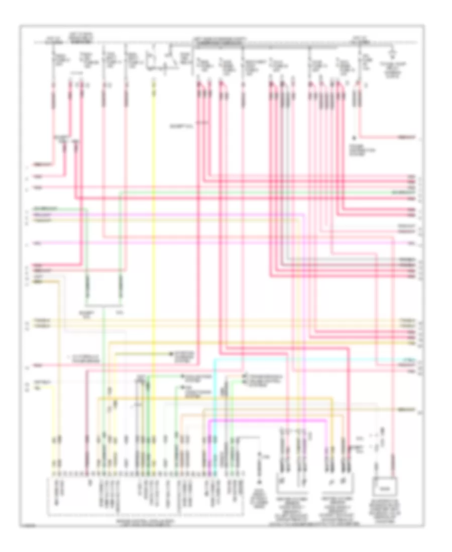
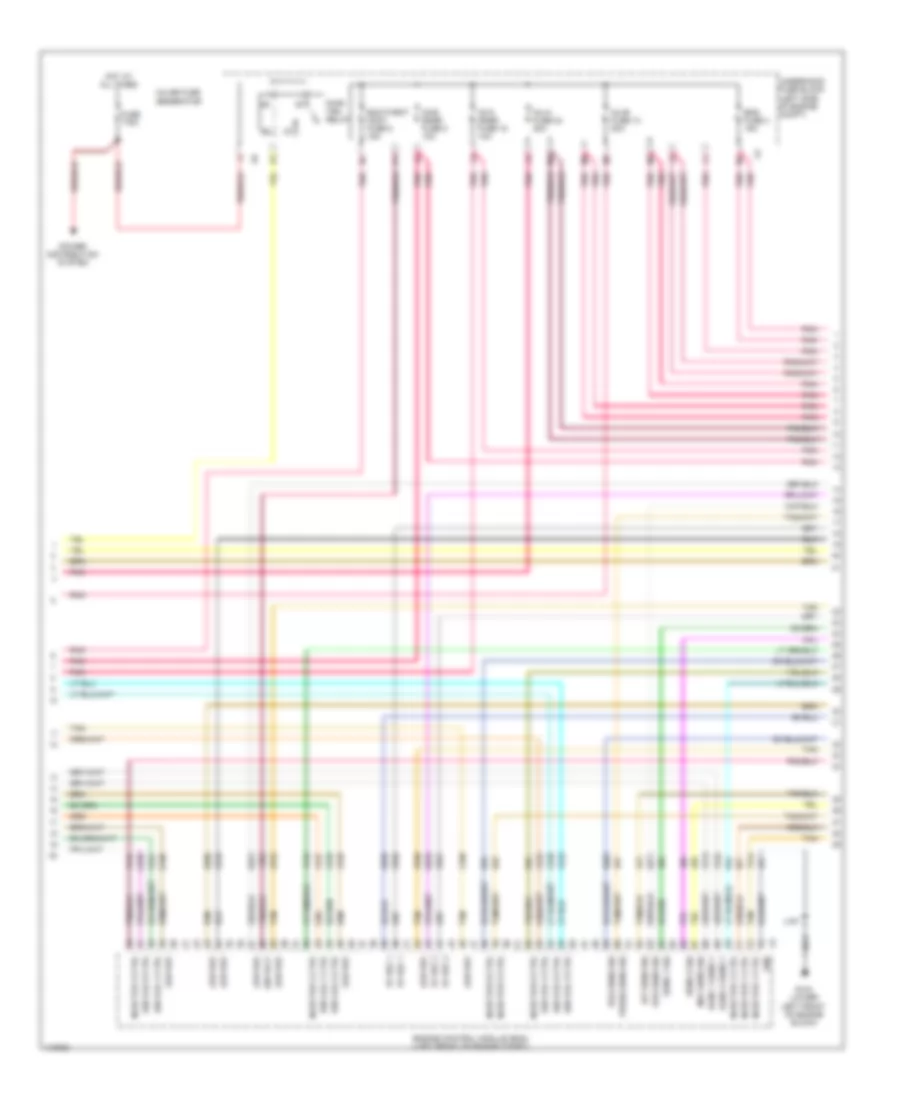
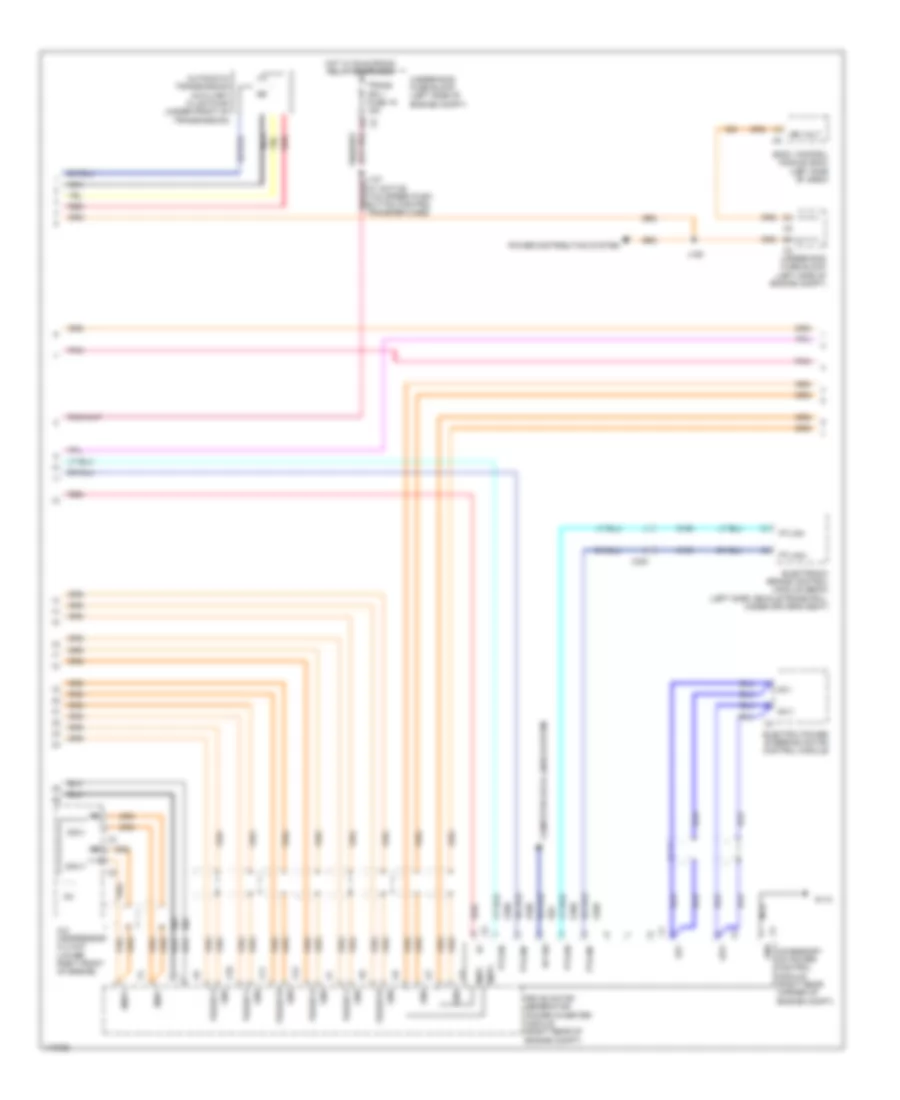
5.3L VIN 0, Engine Performance Wiring Diagram (1 of 6) for Chevrolet Tahoe LS 2013

List of elements for 5.3L VIN 0, Engine Performance Wiring Diagram (1 of 6) for Chevrolet Tahoe LS 2013:
- (10 series: chassis harness 5 cm from breakout to fuel tank) (20 series: chassis harness 5 cm from breakout to rear fuel pump)
- (fuel pump flow control module: on right side frame rail) (except 6.0l w/ integrated trailer brake) fuel pump/trailer brake control module (except 6.0l w/o integrated trailer brake) fuel pump flow control module
- (on 3rd body mount) (w/ 20 series) g305 g400 (w/ 10 series) (left rear body mount)
- (on fuel rail assembly) fuel pressure sensor
- (or 239)
- 5 volt ref
- 5v ref
- 5v ref 1
- 6.0l
- Accelerator pedal position (app) sensor (top of accelerator pedal assembly)
- Air conditioning system
- Bank 1 sens 2
- Body control module (bcm) (left side of dash)
- Brake pedal position (bpp) sensor (top of brake pedal assembly)
- Brake sw sig
- Brk sens sig
- Brk snse sig
- Computer data lines system
- Cooling fans system
- Data bus +
- Data bus -
- Engine control module (ecm) (left side of fan shroud)
- Except 6.0l
- Extension shld
- Exterior lights system
- Fan rly ctrl
- Front fuel pump & sender assembly (except 6.0l) (inside primary fuel tank)
- Fuel tank pressure (ftp) sensor (on fuel pump & sender assembly)
- G103 (front of right cylinder head)
- Gnd
- Iat sens sig
- Ign volt
- Ign voltage
- J106
- J331
- J364 (chassis harness, 13 cm from fuel pump flow control module breakout)
- Level sens sig
- Low ref
- Maf
- Mass air flow (maf)/intake air temperature (iat) sensor (on engine air cleaner box)
- Nca
- P/n sig
- Pnk
- Pnk d
- Pos sens 1 sig
- Pos sens 2 sig
- Press sens sig
- Pump ctrl
- Relay ctrl
- Sens sig
- Serial data
- Tan
- Tan a
- Transfer case & two speed active transfer case push button control
- Transmissions system
- W/ active 2 speed push button control transfer case
- W/ integrated trailer brake
- W/ single speed active
- W/o active 2 speed push button control transfer case
- W/o integrated trailer brake
- W/o single speed active transfer case & two speed active transfer case push button control
- X109
- X123
- X131
- X205
- X300
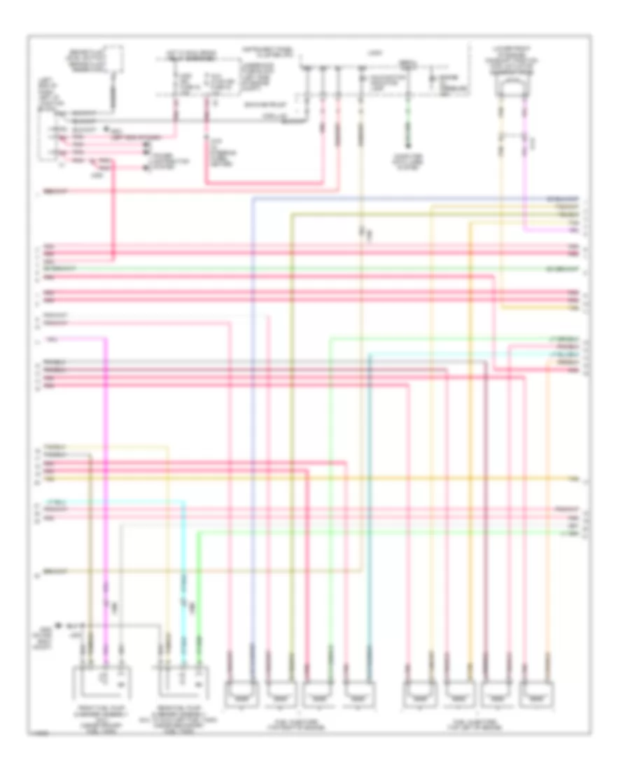
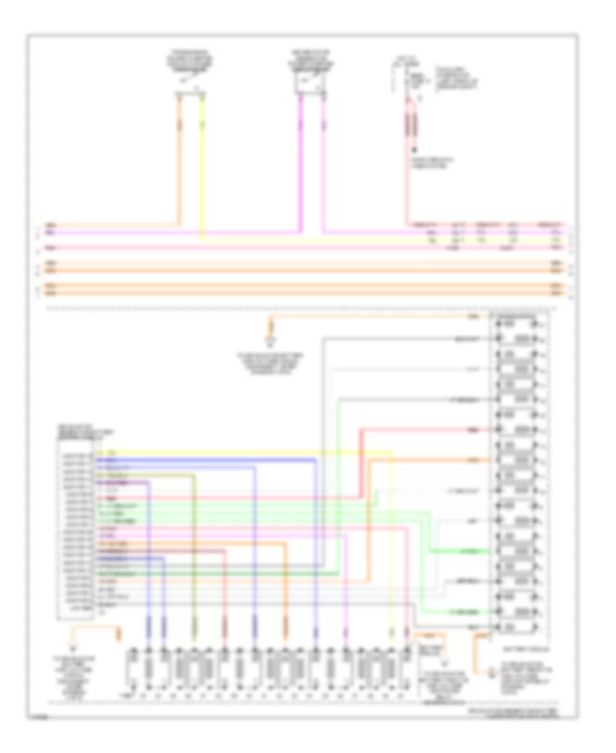
5.3L VIN 0, Engine Performance Wiring Diagram (2 of 6) for Chevrolet Tahoe LS 2013
List of elements for 5.3L VIN 0, Engine Performance Wiring Diagram (2 of 6) for Chevrolet Tahoe LS 2013:
- (left side of engine compt) underhood fuse block
- (not used) x300
- (or 821)
- 5v ref 1
- 6.0l
- Air conditioning system
- Bank 1 sens 2
- Bank 2 sens 2
- Clutch rly ctrl
- Cooling fans system
- Ecm- batt fuse 12 10a
- Ecm- ign fuse 56 15a
- Ecm/throt cont fuse 5 15a
- Enable rly ctrl
- Eng fuse 4 15a
- Engine control module (ecm) (left side of fan shroud)
- Evaporative emission (evap) canister vent solenoid valve (near evap canister)
- Except 6.0l
- Fan rly ctrl
- Fscm fuse 21 20a
- G103 (front of right cylinder head)
- Ground
- Heated oxygen sensor (ho2s) bank 1 sensor 2 (in left exhaust, downstream of catalytic converter)
- Heated oxygen sensor (ho2s) bank 2 sensor 2 (in right exhaust, downstream of catalytic converter)
- Hot at all times
- Hot w/ run/ crank relay energized
- Ign
- Inj-a fuse 24 20a
- Inj-b fuse 13 20a
- Ipc fuse 10a
- J106
- Low ref
- Lvl sens sig
- Maf sens sig
- Mil ctrl
- Nca
- O2-a snsr fuse 18 10a
- O2-b snsr fuse 8 10a
- Pnk
- Pnk d
- Power brake
- Power distribution system
- Pump rly ctrl
- Pwr/ trn relay
- Rly coil ctrl
- Sig return
- Speed sig
- Starting/ charging system
- Tan
- Tan a
- Tcm- batt fuse 14 15a
- To fuel pump relay diagram (5 of 6)
- Tos sig
- Transmissions & cruise control systems
- Vent sol ctrl
- W/ hydraulic
- X131
- X300
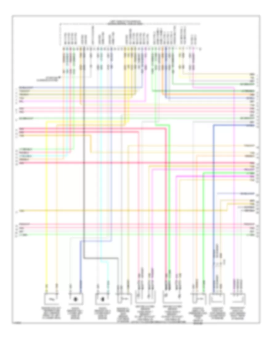
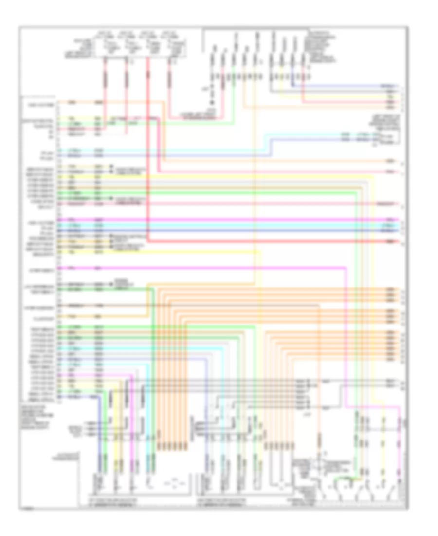
5.3L VIN 0, Engine Performance Wiring Diagram (3 of 6) for Chevrolet Tahoe LS 2013
List of elements for 5.3L VIN 0, Engine Performance Wiring Diagram (3 of 6) for Chevrolet Tahoe LS 2013:
- (left end of dash) left i/p junction block
- (lower front of engine) camshaft position (cmp) actuator solenoid valve
- Aux hvac-ign fuse 48 10a
- Brake fluid level switch (brake fluid reservoir)
- Cadillac
- Computer data lines system
- Engine oil pressure ind
- Front fuel pump & sender assembly (6.0l) (inside primary fuel tank)
- Fuel injectors (top left of engine)
- Fuel injectors (top right of engine)
- G201 (left end of dash)
- G300 (on 2nd body mount)
- Gmc/chevrolet
- Gnd
- Hot w/ run/ crank relay energized
- Ign
- Instrument panel cluster (ipc)
- J219 (w/ steering wheel heater)
- J300
- Logic
- Malfunction indicator lamp
- Misc ign fuse 43 10a
- Pnk
- Pnk a
- Power distribution system
- Rear fuel pump & sender assembly (6.0l w/ auxiliary fuel tank) (inside secondary fuel tank)
- Serial data
- Tan
- Tan b
- Underhood fuse block (left side of engine compt)
- X109
- X112
- X205
- X300
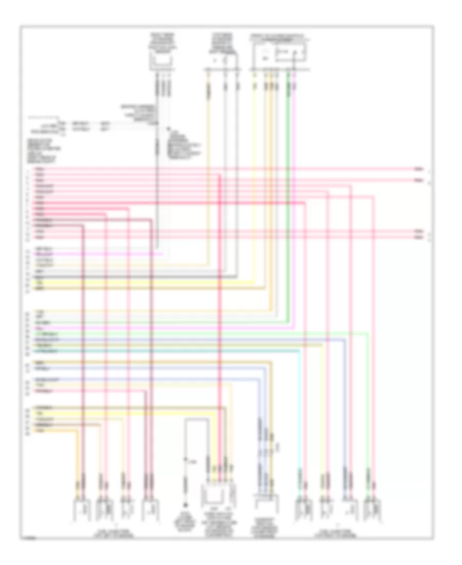
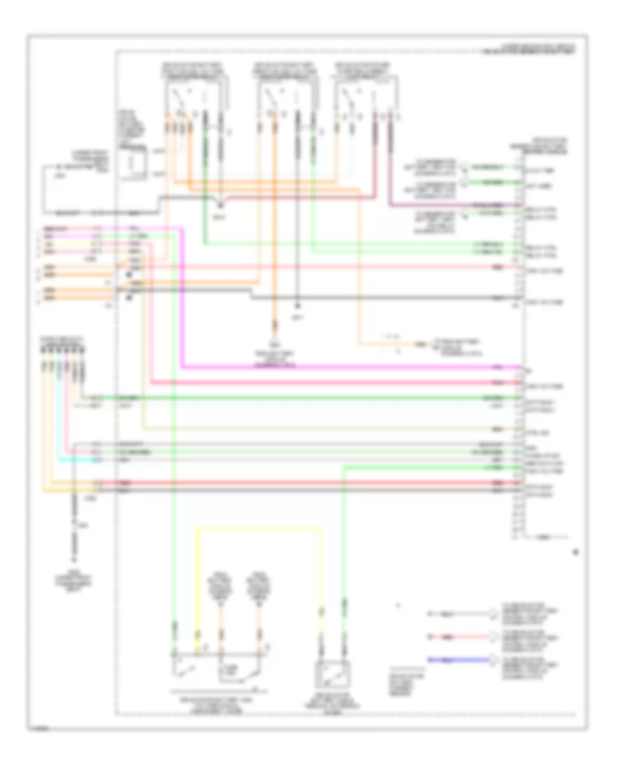
5.3L VIN 0, Engine Performance Wiring Diagram (4 of 6) for Chevrolet Tahoe LS 2013
List of elements for 5.3L VIN 0, Engine Performance Wiring Diagram (4 of 6) for Chevrolet Tahoe LS 2013:
- (left side of fan shroud) engine control module (ecm)
- 5v ref 2
- Bank 1 sens 1
- Bank 2 sens 1
- Camshaft position (cmp) sensor (lower front of engine)
- Crankshaft position (ckp) sensor (right rear of engine)
- Duty cycle sig
- Ect sens sig
- Engine coolant temperature (ect) sensor (front of left cylinder head)
- Engine oil pressure (eop) sensor (top rear of engine)
- Heated oxygen sensor (ho2s) bank 1 sensor 1 (in left exhaust, upstream of catalytic converter)
- Heated oxygen sensor (ho2s) bank 2 sensor 1 (in right exhaust, upstream of catalytic converter)
- Inj 1 ctrl
- Inj 2 ctrl
- Inj 3 ctrl
- Inj 4 ctrl
- Inj 5 ctrl
- Inj 6 ctrl
- Inj 7 ctrl
- Inj 8 ctrl
- Knock sensor (ks) 1 (lower left side of engine)
- Knock sensor (ks) 2 (lower right side of engine)
- Low ref
- Manifold absolute pressure (map) sensor (top rear of engine)
- Nca
- Pnk
- Purge sol ctrl
- Sens 1 sig
- Sens 2 sig
- Sol ctrl
- Sol ctrl 1
- Sol ctrl 2
- Sol ctrl 3
- Sol ctrl 4
- Starting/ charging system
- Tac mtr ctrl 1
- Tac mtr ctrl 2
- Tan
- X112
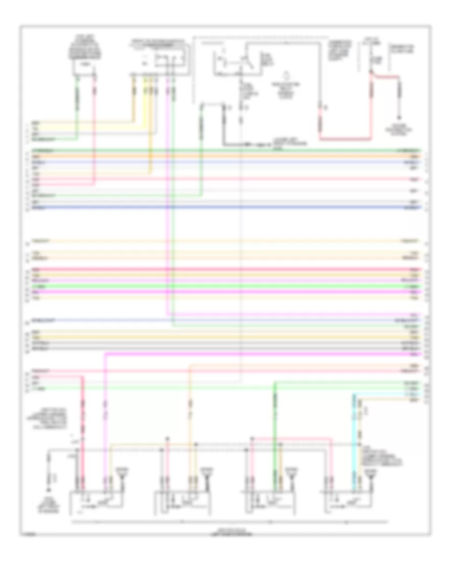
5.3L VIN 0, Engine Performance Wiring Diagram (5 of 6) for Chevrolet Tahoe LS 2013
List of elements for 5.3L VIN 0, Engine Performance Wiring Diagram (5 of 6) for Chevrolet Tahoe LS 2013:
- (front of intake manifold) throttle body
- (ignition coil jumper harness, approximately 3 cm from ignition coil 5 breakout)
- (lower left front of engine) g102
- (top left of engine) evaporative emission (evap) canister purge solenoid valve
- From pwr/trn relay diagram (2 of 6)
- Fuel pump fuse 20 20a
- Fuel pump relay
- Fuse 175a
- G102 (lower left front of engine)
- Generator inline fuse
- Hot at all times
- Ignition coils (left side of engine)
- J105
- J107
- J108
- J109 (ignition coil jumper harness, approximately 5 cm from x111 breakout)
- Nca
- Pnk
- Pnk d
- Power distribution system
- Spark plug
- Tan
- Underhood fuse block (left side of engine compt)
- X111
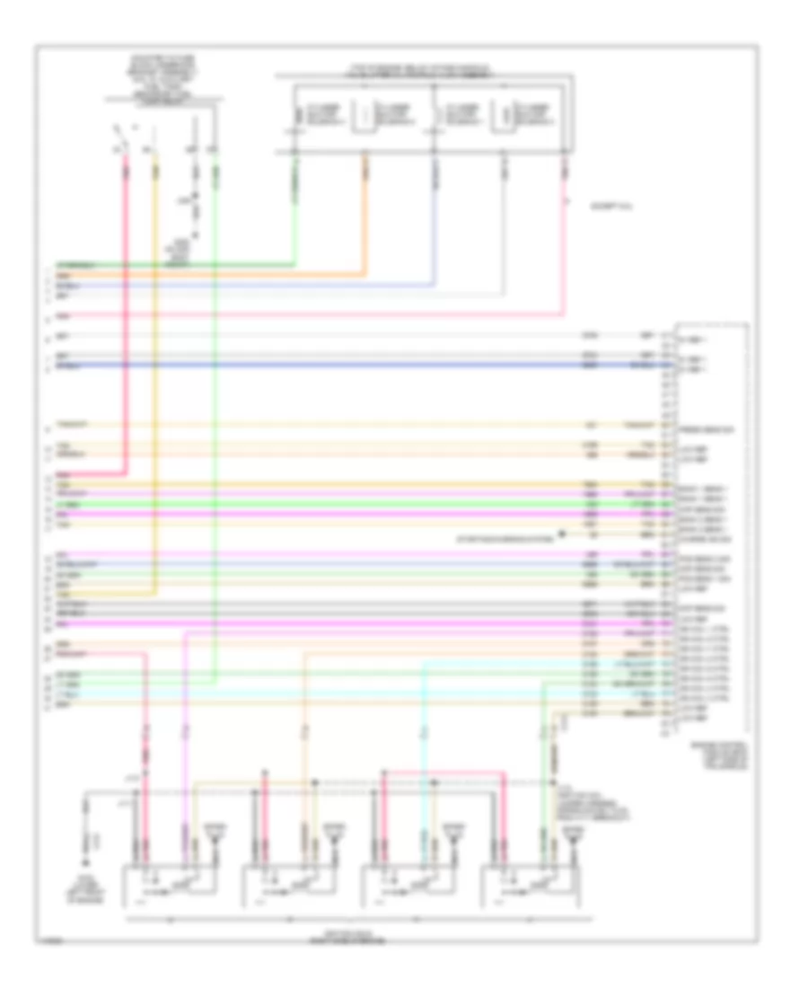
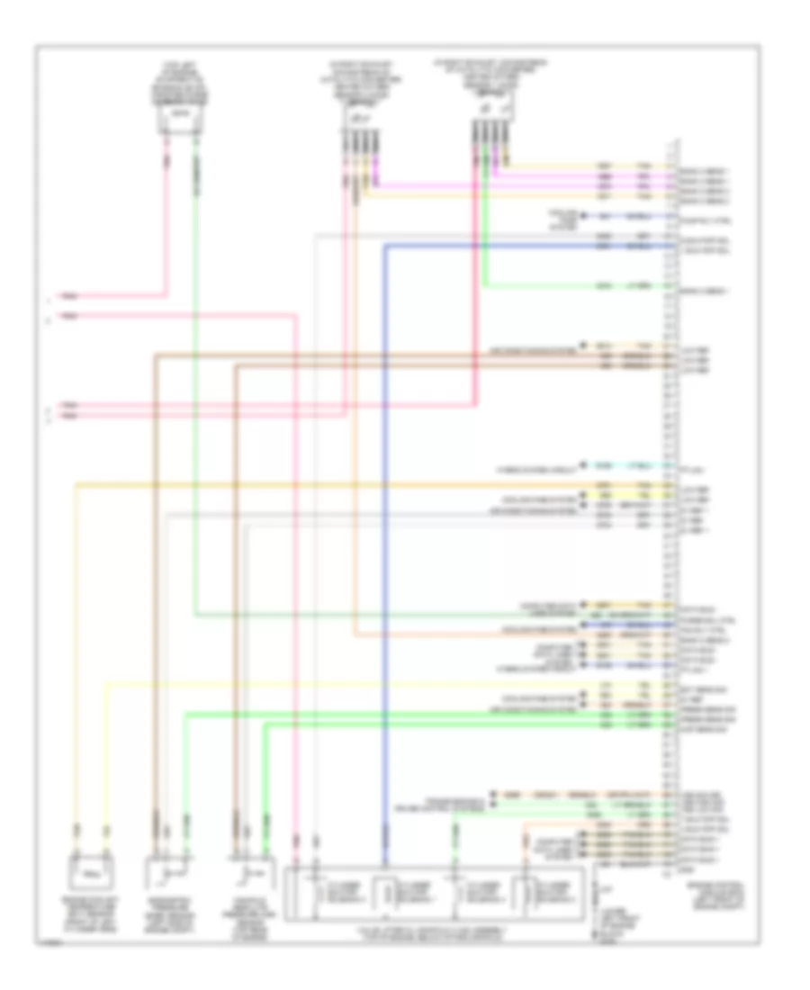
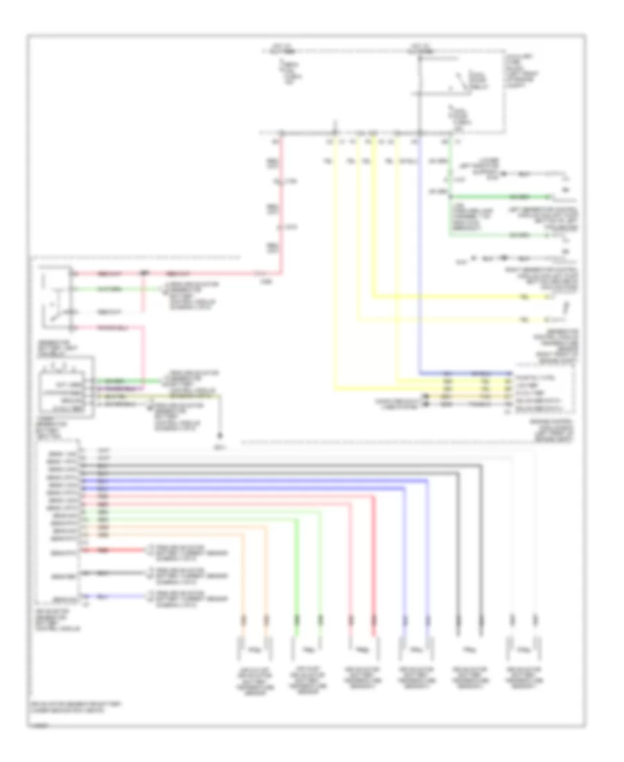
5.3L VIN 0, Engine Performance Wiring Diagram (6 of 6) for Chevrolet Tahoe LS 2013
List of elements for 5.3L VIN 0, Engine Performance Wiring Diagram (6 of 6) for Chevrolet Tahoe LS 2013:
- (mounted to fuse block underhood bracket assembly) (6.0l w/ auxiliary fuel tank) secondary fuel pump relay
- (top of engine, below intake manifold) valve lifter oil manifold (vlom) assembly
- 5v ref 1
- Bank 1 sens 1
- Bank 2 sens 1
- Charge ind sig
- Ckp sens sig
- Cmp sens sig
- Cylinder shutoff solenoid 1
- Cylinder shutoff solenoid 2
- Cylinder shutoff solenoid 3
- Cylinder shutoff solenoid 4
- E pnk
- Engine control module (ecm) (left side of fan shroud)
- Except 6.0l
- G102 (lower left front of engine)
- G300 (on 2nd body mount)
- Ign coil 1 ctrl
- Ign coil 2 ctrl
- Ign coil 3 ctrl
- Ign coil 4 ctrl
- Ign coil 5 ctrl
- Ign coil 6 ctrl
- Ign coil 7 ctrl
- Ign coil 8 ctrl
- Ignition coils (right side of engine)
- J110
- J111
- J112 (ignition coil jumper harness, approximately 5 cm from x111 breakout)
- J300
- Low ref
- Map sens sig
- Nca
- Pnk
- Pnk d
- Pos sens 1 sig
- Pos sens 2 sig
- Press sens sig
- Spark plug
- Starting/charging system
- Tan
- X113
6.0L VIN J
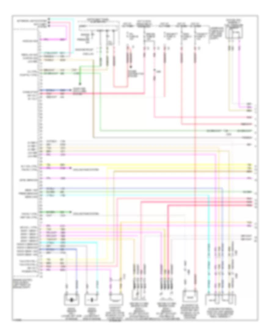
6.0L VIN J, Engine Controls Wiring Diagram (1 of 6) for Chevrolet Tahoe LS 2013
List of elements for 6.0L VIN J, Engine Controls Wiring Diagram (1 of 6) for Chevrolet Tahoe LS 2013:
- (on fuel rail assembly) fuel pressure sensor
- 5v ref 1
- 5v ref 2
- Accelerator pedal position (app) sensor (top of accelerator pedal assembly)
- Ajar sw sig
- Anti-theft system
- B+ volt
- Bank 1 sens 1
- Bank 1 sens 2
- Cadillac
- Camshaft position (cmp) actuator solenoid valve (lower front of engine)
- Computer data lines system
- Cooling fans system
- Data
- Ecm-batt fuse 12 10a
- Ecm-ign fuse 56 15a
- Engine control module (ecm) (left front of engine compt)
- Engine oil pressure ind
- Evaporative emission (evap) canister vent solenoid valve (near evap canister)
- Exterior lights system
- Fan rly ctrl
- Fscm fuse 21 20a
- Gmc/chevrolet
- Heated oxygen sensor (ho2s) bank 1 sensor 1 (in left exhaust, upstream of catalytic converter)
- Heated oxygen sensor (ho2s) bank 1 sensor 2 (in left exhaust, downstream of catalytic converter)
- Hood sw sig
- Hot at all times
- Hot w/ run/ crank relay energized
- Ign
- Ign coil 1 ctrl
- Ign volt
- Instrument panel cluster (ipc)
- Ipc fuse 46 10a
- J365
- Knock 2 sens sig
- Knock sens 1 sig
- Knock sensor (ks) 1 (lower left side of engine)
- Knock sensor (ks) 2 (lower right side of engine)
- Level sens sig
- Logic
- Low ref
- Mil ctrl
- Mil ind
- Nca
- Pedal sw sig
- Phasor ctrl
- Pnk
- Power distribution system
- Press sens sig
- Pump rly ctrl
- Rly coil ctrl
- Sens 1 sig
- Sens 2 sig
- Tac mtr ctrl 1
- Tac mtr ctrl 2
- Tan
- Tcm-batt fuse 14 10a
- Underhood fuse block (left side of engine compt)
- Vent sol ctrl
- Wake-up sig
- X109
- X112
- X205
- X300
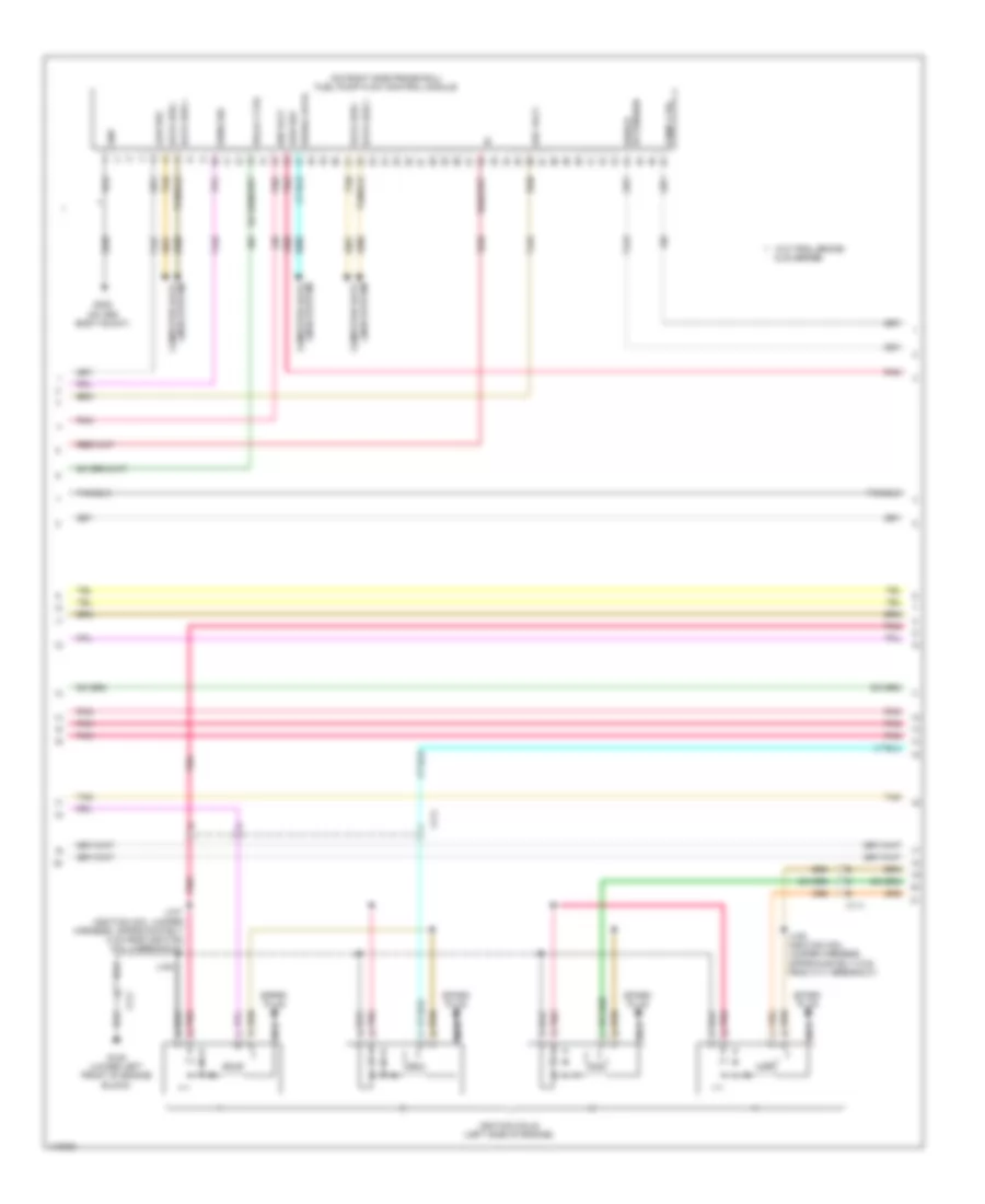
6.0L VIN J, Engine Controls Wiring Diagram (2 of 6) for Chevrolet Tahoe LS 2013
List of elements for 6.0L VIN J, Engine Controls Wiring Diagram (2 of 6) for Chevrolet Tahoe LS 2013:
- & 20 series
- (on right side frame rail) fuel pump flow control module
- Computer data lines system
- Data bus +
- Data bus -
- Extension shield
- G105 (lower left front of engine block)
- G305 (on 3rd body mount)
- Gnd
- Ign volt
- Ignition coils (left side of engine)
- J107 (ignition coil jumper harness, approximately 3 cm from ignition coil 5 breakout)
- J108
- J109 (ignition coil jumper harness, approximately 5 cm from x111 breakout)
- Lines system computer data
- Low ref
- Nca
- Pnk
- Pnk d
- Pump ctrl
- Ref volt
- Relay ctrl
- Sens sig
- Serial data
- Spark plug
- Tan
- W/o trail brake
- X111
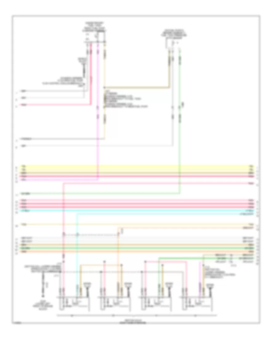
6.0L VIN J, Engine Controls Wiring Diagram (3 of 6) for Chevrolet Tahoe LS 2013
List of elements for 6.0L VIN J, Engine Controls Wiring Diagram (3 of 6) for Chevrolet Tahoe LS 2013:
- (chassis harness, 13 cm from fuel pump flow control module breakout) j364
- (inside primary fuel tank) front fuel pump & sender assembly
- (on fuel pump & sender assembly) fuel tank pressure (ftp) sensor
- G105 (lower left front of engine block)
- Ignition coils (right side of engine)
- J110 (ignition coil jumper harness, approximately 3 cm from ignition coil 4 breakout)
- J111
- J112 (ignition coil jumper harness, approximately 5 cm from x111 breakout)
- Nca
- Pnk
- Pnk d
- Spark plug
- Tan
- X113
- X300
6.0L VIN J, Engine Controls Wiring Diagram (4 of 6) for Chevrolet Tahoe LS 2013
List of elements for 6.0L VIN J, Engine Controls Wiring Diagram (4 of 6) for Chevrolet Tahoe LS 2013:
- 5v ref 1
- 5v ref 2
- Bank 1 sens 1
- Bank 2 sens 1
- Ecm/throt cont fuse 5 15a
- Eng fuse 4 15a
- Engine control module (ecm) (left front of engine compt)
- Fuse 175a
- G103 (lower left front of engine block)
- Gnd
- Hot at all times
- Iat sens sig
- Ign coil 2 ctrl
- Ign coil 3 ctrl
- Ign coil 4 ctrl
- Ign coil 5 ctrl
- Ign coil 6 ctrl
- Ign coil 7 ctrl
- Ign coil 8 ctrl
- Ign volt
- Inj-a fuse 24 20a
- Inj-b fuse 13 20a
- Injector 1 ctrl
- Injector 2 ctrl
- Injector 3 ctrl
- Injector 4 ctrl
- Injector 5 ctrl
- Injector 6 ctrl
- Injector 7 ctrl
- Injector 8 ctrl
- Inline fuse generator
- J157
- Low ref
- Maf sens sig
- O2-a snsr fuse 18 10a
- O2-b snsr fuse 8 10a
- Pnk
- Pos sens sig
- Power distribution system
- Press sens sig
- Pwr/ trn relay
- Sens 1 sig
- Sens 2 sig
- Tan
- Underhood fuse block (left side of engine compt)
6.0L VIN J, Engine Controls Wiring Diagram (5 of 6) for Chevrolet Tahoe LS 2013
List of elements for 6.0L VIN J, Engine Controls Wiring Diagram (5 of 6) for Chevrolet Tahoe LS 2013:
- (engine harness, 42 cm from throttle body breakout) j154
- (front of intake manifold) throttle body
- (right rear of engine) crankshaft position (ckp) sensor
- (top rear of engine) engine oil pressure (eop) sensor
- Approximately 48 cm from throttle body breakout)
- Camshaft position (cmp) sensor (lower front of engine)
- Drive motor generator power inverter module (right rear of engine compt)
- Fuel injectors (top left of engine)
- Fuel injectors (top right of engine)
- G103 (lower left front of engine block)
- Iat
- J106
- Low ref
- Maf
- Mass air flow (maf)/intake air temperature (iat) sensor (on engine air cleaner box)
- Pnk
- Pos sens sig
- Tan
- X112
6.0L VIN J, Engine Controls Wiring Diagram (6 of 6) for Chevrolet Tahoe LS 2013
List of elements for 6.0L VIN J, Engine Controls Wiring Diagram (6 of 6) for Chevrolet Tahoe LS 2013:
- (in right exhaust, downstream of catalytic converter) heated oxygen sensor 1 (ho2s) bank 2
- (in right exhaust, downstream of catalytic converter) heated oxygen sensor 2 (ho2s) bank 2
- (lower left front of engine block) g103
- (or 821)
- (top left of engine) evaporative emission (evap) canister purge solenoid valve
- 1 shutoff sol
- 4 shutoff sol
- 5v ref
- 5v ref 1
- 6 shutoff sol
- 7 shutoff sol
- Air conditioning system
- Bank 2 sens 1
- Bank 2 sens 2
- Barometric pressure (baro) sensor (left side of engine compt)
- Computer data lines system
- Cooling fans system
- Cylinder shutoff solenoid 1
- Cylinder shutoff solenoid 2
- Cylinder shutoff solenoid 3
- Cylinder shutoff solenoid 4
- Data bus +
- Data bus -
- Ect sens sig
- Engine control module (ecm) (left front of engine compt)
- Engine coolant temperature (ect) sensor (front of left cylinder head)
- Fan rly ctrl
- Gnd
- Hybrid system circuit
- J157
- Low ref
- Manifold absolute pressure (map) sensor (top rear of engine)
- Map sens sig
- Nca
- Pnk
- Press sens sig
- Ptlan +
- Ptlan -
- Pump rly ctrl
- Purge sol ctrl
- Tan
- Transmissions & cruise control systems
- Valve lifter oil manifold (vlom) assembly (top of engine, below intake manifold)
- Vss sig (or) vss high sig vss low sig
6.0L VIN J, Hybrid System Wiring Diagram (1 of 5) for Chevrolet Tahoe LS 2013
List of elements for 6.0L VIN J, Hybrid System Wiring Diagram (1 of 5) for Chevrolet Tahoe LS 2013:
- (left front of engine compt) engine control module (ecm)
- 1st position drive motor (w/ generator assembly)
- 2nd position drive motor (w/ generator assembly)
- Automatic transmi- ssion internal mode switch (ims)
- Automatic transmission
- Automatic transmission auxiliary fluid pump control module (left side of engine compt)
- Auxiliary fuse block (left front of engine compt)
- B+ nca
- C6 pnk
- Circuit 1
- Circuit 2
- Circuit excitation
- Computer data lines system
- Contactor ctrl
- Control solenoid valve asse- mbly
- Drain wire nca
- Drive motor generator power inverter module (right rear of engine compt)
- Engine controls circuit
- Excitation circuit
- Fluid pump
- Fluid pump nca
- G103 (lower left front of engine block)
- Gnd nca
- High voltage
- Hot at all times
- Ign nca
- Ign volt
- Inter mode gnd
- Inter mode r1
- Inter mode r2
- Inter mode r3
- Inter mode r4
- Inter mode s
- J146
- J147
- Low reference
- Mega fuse 200a
- Mtr a s1 sig
- Mtr a s2 sig
- Mtr a s3 sig
- Mtr a s4 sig
- Mtr b s1 sig
- Mtr b s2 sig
- Mtr b s3 sig
- Mtr b s4 sig
- Nca
- Phase a nca
- Phase b nca
- Phase c nca
- Pim 1 fuse 8 15a
- Pim 2 fuse 9 15a
- Pnk
- Pos sens sig
- Ptlan+
- Ptlan-
- Pump ctrl
- Pump ctrl nca
- Red
- Resol mtr a+
- Resol mtr b+
- Resol mtr b-
- Sens b rtn
- Ser data bus+
- Ser data bus-
- Tan
- Temp sens a
- Temp sens b
- Trans pump fuse 60a
- Transmission control module (tcm) x2
- Wake up sig
- X150
- X175
- X215
6.0L VIN J, Hybrid System Wiring Diagram (2 of 5) for Chevrolet Tahoe LS 2013
List of elements for 6.0L VIN J, Hybrid System Wiring Diagram (2 of 5) for Chevrolet Tahoe LS 2013:
- (w/ active two speed push button control transfer case)
- 300v+
- 300v-
- 42v+
- 42v-
- A/c compressor clutch (lower right front of engine)
- Accessory dc power control module (right rear corner of engine compt)
- Automatic transmission auxiliary fluid pump (under front of transmission)
- Body control module (bcm) (left side of dash)
- Computer data lines system
- Drive motor generator power inverter module (right rear of engine compt)
- Electric power steering motor control module
- Electronic brake control module (ebcm) (left side vehicle frame rail, under driver's seat)
- G112
- Gnd
- Hot w/ run/crank relay energized
- Ign volt
- J155
- Nca
- Phase u
- Phase v
- Phase w
- Pnk
- Power distribution system
- Ptlan+
- Ptlan-
- Red
- Trans ign 1 fuse 19 15a
- Underhood fuse block (left side of engine compt)
- Up sig
- X10
- X11
- X12
- X300
6.0L VIN J, Hybrid System Wiring Diagram (3 of 5) for Chevrolet Tahoe LS 2013
List of elements for 6.0L VIN J, Hybrid System Wiring Diagram (3 of 5) for Chevrolet Tahoe LS 2013:
- Auxiliary fuse block (left front of engine compt)
- Battery module
- Becm fuse 10 15a
- Computer data lines system
- Drive motor generator battery (under second row seats)
- Drive motor generator battery control module
- Driver motor generator power inverter module cover
- Hot at all times
- Low ref
- Monitor 1
- Monitor 10
- Monitor 11
- Monitor 12
- Monitor 13
- Monitor 14
- Monitor 15
- Monitor 16
- Monitor 17
- Monitor 18
- Monitor 19
- Monitor 2
- Monitor 20
- Monitor 3
- Monitor 4
- Monitor 5
- Monitor 6
- Monitor 7
- Monitor 8
- Monitor 9
- Pnk
- Red
- To drive motor battery high voltage manual disconnect lever (diagram 4 of 5)
- To drive motor battery positive high voltage contactor relay (diagram 4 of 5)
- Transmission power inverter module (3 phase) cable cover
- X150
- X215
6.0L VIN J, Hybrid System Wiring Diagram (4 of 5) for Chevrolet Tahoe LS 2013
List of elements for 6.0L VIN J, Hybrid System Wiring Diagram (4 of 5) for Chevrolet Tahoe LS 2013:
- (under front passenger's seat) g302
- (under second row seats) drive motor generator battery
- 5-volt ref
- Computer data lines system
- Ctrl sig
- Data bus +
- Data bus -
- Drive motor battery cable terminal extension cover
- Drive motor battery current sensor
- Drive motor battery high voltage manual disconnect lever
- Drive motor battery inverter current limit resistor
- Drive motor battery positive high voltage contactor relay
- Drive motor generator battery control module
- Drive motor power inverter current limit relay
- From battery module (diagram 3 of 5)
- Fuse 125a
- G302 (under front passenger's seat)
- G311
- G312
- Gnd
- High voltage
- J302
- Nca
- Not used
- Pnk
- Red
- Relay ctrl
- Ser data com
- Tan
- To drive motor generator battery control module (diagram 5 of 5)
- To generator battery vent fan (diagram 5 of 5)
- To generator battery vent fan relay (diagram 5 of 5)
- Wake up sig
- X355
6.0L VIN J, Hybrid System Wiring Diagram (5 of 5) for Chevrolet Tahoe LS 2013
List of elements for 6.0L VIN J, Hybrid System Wiring Diagram (5 of 5) for Chevrolet Tahoe LS 2013:
- (diagram 4 of 5)
- (lower left radiator support) g100
- 5-volt ref
- Air inlet drive motor battery temperature sensor
- Air outlet drive motor battery temperature sensor
- Auxiliary fuse block (left front of engine compt)
- Becm fan fuse 2 15a
- C8 x150
- Computer data lines system
- Cool pump fuse 6 15a
- Cool pump relay
- Drive motor battery temperature sensor 1
- Drive motor battery temperature sensor 2
- Drive motor battery temperature sensor 3
- Drive motor battery temperature sensor 4
- Drive motor generator battery (under second row seats)
- Drive motor generator battery control module
- Engine control module (ecm) (left front of engine compt)
- From drive motor battery current sensor (diagram 4 of 5)
- From drive motor battery current sensor h
- From drive motor battery current sensor j
- From drive motor generator battery control module (diagram 4 of 5)
- G101
- G311
- Generator battery vent fan
- Generator battery vent fan relay
- Generator control module temperature sensor (right front of engine compt)
- Gmlan ser data +
- Gmlan ser data -
- Ground
- Hot at all times
- J x215
- J101
- J164 (forward lamp harness, 7 cm from g100 breakout)
- J395
- Left generator control module coolant pump (bottom of left cooling fan)
- Logic
- Low ref
- Mtr pwr feed
- Not used
- Pump rly ctrl
- Red
- Right generator control module coolant pump (bottom center of cooling fans)
- Sens 1 rtn
- Sens 1 sig
- Sens 2 rtn
- Sens 2 sig
- Sens 3 rtn
- Sens 3 sig
- Sens 4 rtn
- Sens 4 sig
- Sens ref
- Sens rtn
- Sens sig
- Tan
- X127 d
- X355