ENGINE PERFORMANCE
2.0L
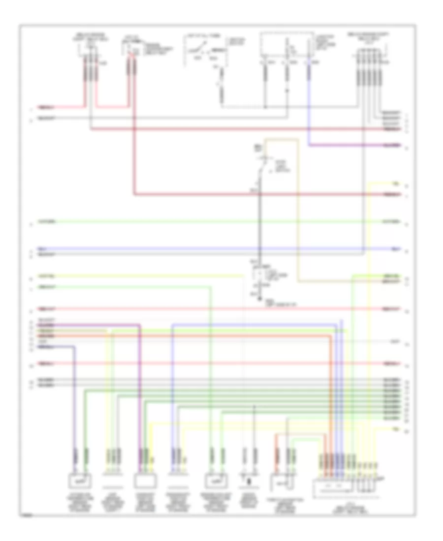
2.0L, Engine Performance Wiring Diagrams (1 of 3) for Dodge Avenger ES 1996

List of elements for 2.0L, Engine Performance Wiring Diagrams (1 of 3) for Dodge Avenger ES 1996:
- (behind foot distribution duct)
- (behind left headlight)
- (below engine compt. relay box) j/c 3
- (left side of safety wall) asd relay
- A-28
- A-77
- Abs- ecu
- Auto-cruise control main switch & auto-cruise control relay
- Automatic compressor- ecm
- B-41
- B-54
- Brake
- C-04
- C-05
- C-06
- Capacitor
- Charge
- Check engine
- Combination meter (instrument cluster)
- Cruise
- Dual pressure switch (a/c) & a/c compressor clutch relay
- Field coil
- Fuel
- Fuel gauge unit (sender)
- Fuel injectors
- G106
- G202 (left side of i/p)
- G302
- Generator
- Heated oxygen sensor 1
- Heated oxygen sensor 2
- Ignition coil
- Junction block (left side of i/p)
- Nca
- Powertrain control module (left side of engine compt.)
- Radiator fan relay (hi2)
- Red
- Spark plugs
- Tacho- meter
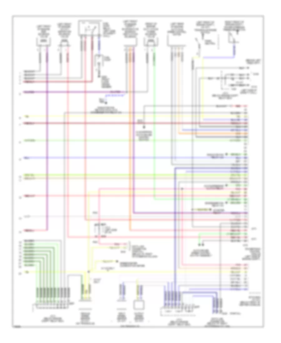
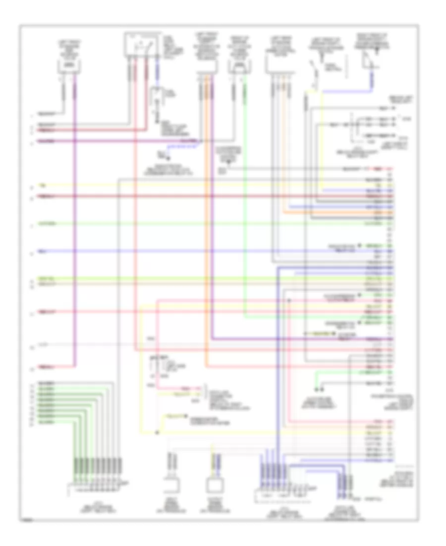
2.0L, Engine Performance Wiring Diagrams (2 of 3) for Dodge Avenger ES 1996
List of elements for 2.0L, Engine Performance Wiring Diagrams (2 of 3) for Dodge Avenger ES 1996:
- (below engine compt. relay box) j/c 3
- (below engine compt. relay box) j/c 4
- A-28
- A-29
- Acc
- B-06
- B-41
- B-54
- B-63
- Camshaft position sensor (left side of engine)
- Crankshaft position sensor (right front of engine)
- Engine compartment relay box
- Engine coolant temperature sensor (right front of engine)
- F8 10a
- Fl3 30a
- G202 (left side of i/p)
- Hot at all times
- Ig1 nca
- Ignition switch
- Intake air temperature sensor (right rear of engine)
- J/c 2 (left side of i/p)
- J/c 4 (below engine compt. relay box)
- Junction block (left side of i/p)
- Knock sensor (front of engine)
- Lock
- Map sensor (right rear of engine compt.)
- Run
- Start
- Stop light switch
- Throttle position sensor (left rear of engine)
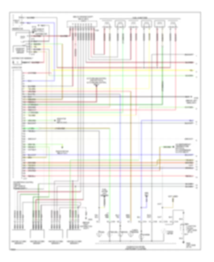
2.0L, Engine Performance Wiring Diagrams (3 of 3) for Dodge Avenger ES 1996
List of elements for 2.0L, Engine Performance Wiring Diagrams (3 of 3) for Dodge Avenger ES 1996:
- (a/t)
- (behind left headlight)
- (front of engine) duty cycle purge solenoid valve
- (left front of engine compt.) (w/ a/t)
- (left front of engine compt.) evaporative emission ventilation solenoid
- (left front of engine) (w/ m/t) aspirator solenoid valve
- (left front of engine) egr solenoid valve
- (left rear of engine)
- (left side of safety wall)
- (m/t)
- (on transaxle)
- (partial)
- (right front of engine compt.)
- A-28
- A-29
- A-78
- A/c compressor clutch relay
- Auto idle speed control motor
- Auto-cruise speed control switch assembly
- B-06
- B-29
- B-30
- Clockspring (auto-cruise control switch)
- Condenser fan relay (hi)
- Data link connector (below i/p, right of steering column)
- Data link connector (partial) (below i/p, right of steering column)
- Etax-ecm (w/ a/t) (below front of center console)
- Fuel pump
- Fuel pump relay (left side of safety wall)
- G106
- G116
- G300 (front floor cross- member)
- Input speed sensor (w/ a/t)
- J/c 2 (left side of i/p)
- J/c 3 (below engine compt. relay box)
- J/c 4 (below engine compt. relay box)
- Output speed sensor (w/ a/t)
- Park/ neutral
- Pnk
- Power steering pressure switch
- Powertrain control module (left side of engine compt.)
- Radiator fan relay (lo)
- Radiator fan relays (hi2 & lo) & condenser fan relay (hi)
- Red
- Speedometer (combination meter)
- Starter relay
- Transaxle range switch
- Vehicle speed sensor (w/ m/t) (on transaxle)
- W/ a/t
- W/ a/t only
- W/ m/t only
2.5L
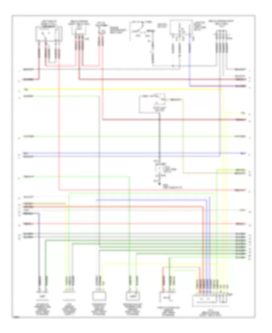
2.5L, Engine Performance Wiring Diagrams (1 of 3) for Dodge Avenger ES 1996
List of elements for 2.5L, Engine Performance Wiring Diagrams (1 of 3) for Dodge Avenger ES 1996:
- (behind foot distribution duct)
- (behind left headlight)
- (below engine compt. relay box) j/c 3
- (left side of safety wall)
- (not used)
- A-28
- A-73
- A-74
- A-77
- A/c refrigerant temperature switch & a/c compressor clutch relay
- Abs- ecu
- Auto-cruise control main switch & auto-cruise control relay
- B-41
- B-54
- Brake
- C-04
- C-05
- C-06
- Camshaft position sensor
- Capacitor
- Charge
- Check engine
- Combination meter (instrument cluster)
- Cruise
- Distributor
- Distributor assembly
- Field coil
- Fuel
- Fuel gauge unit (sender)
- Fuel injectors
- G106
- G116
- G202 (left side of i/p)
- G302
- Generator
- Heated oxygen sensor 1
- Heated oxygen sensor 2
- Heated oxygen sensor 3
- Heated oxygen sensor 4
- Junction block (left side of i/p)
- Nca
- Powertrain control module (left side of engine compt.)
- Radiator fan relay (hi1)
- Radiator fan relay (hi2)
- Red
- Tacho- meter
2.5L, Engine Performance Wiring Diagrams (2 of 3) for Dodge Avenger ES 1996
List of elements for 2.5L, Engine Performance Wiring Diagrams (2 of 3) for Dodge Avenger ES 1996:
- (below engine compt. relay box) j/c 3
- (below engine compt. relay box) j/c 4
- (left side of safety wall) asd relay
- A-28
- A-29
- Acc
- B-06
- B-41
- B-54
- B-63
- Crankshaft position sensor (right front of engine)
- Engine compartment relay box
- Engine coolant temperature sensor (right front of engine)
- F8 10a
- Fl3 30a
- G202 (left side of i/p)
- Hot at all times
- Ig1 nca
- Ignition switch
- Intake air temperature sensor (right rear of engine)
- J/c 2 (left side of i/p)
- J/c 4 (below engine compt. relay box)
- Junction block (left side of i/p)
- Lock
- Map sensor (right rear of engine compt.)
- Run
- Start
- Stop light switch
- Throttle position sensor (left rear of engine)
2.5L, Engine Performance Wiring Diagrams (3 of 3) for Dodge Avenger ES 1996
List of elements for 2.5L, Engine Performance Wiring Diagrams (3 of 3) for Dodge Avenger ES 1996:
- (behind left headlight)
- (front of engine) duty cycle purge solenoid valve
- (left front of engine compt.)
- (left front of engine compt.) evaporative emission ventilation solenoid
- (left front of engine) egr solenoid valve
- (left rear of engine)
- (left side of safety wall)
- (partial)
- (right front of engine compt.)
- A-28
- A-29
- A-78
- A/c compressor clutch relay
- Auto idle speed control motor
- Auto-cruise speed control switch assembly
- B-06
- B-29
- B-30
- Clockspring (auto-cruise control switch)
- Condenser fan relay (hi)
- Data link connector (below i/p, right of steering column)
- Data link connector (partial) (below i/p, right of steering column)
- Etax-ecm (w/ a/t only) (below front of center console)
- Fuel pump
- Fuel pump relay (left side of safety wall)
- G106
- G116
- G300 (front floor upper left crossmember)
- Input speed sensor (on transaxle)
- J/c 2 (left side of i/p)
- J/c 3 (below engine compt. relay box)
- J/c 4 (below engine compt. relay box)
- Output speed sensor (on transaxle)
- Park/ neutral
- Pnk
- Power steering pressure switch
- Powertrain control module (left side of engine compt.)
- Radiator fan relay (lo)
- Radiator fan relays (hi1, hi2 & lo) & condenser fan relay (hi)
- Red
- Speedometer (combination meter)
- Starter relay
- Transaxle range switch