ENGINE PERFORMANCE
2.0L
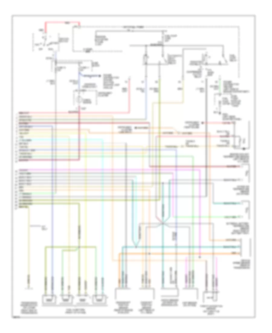
2.0L, Engine Performance Wiring Diagrams (1 of 2) for Dodge Neon High Line 1995

List of elements for 2.0L, Engine Performance Wiring Diagrams (1 of 2) for Dodge Neon High Line 1995:
2.0L, Engine Performance Wiring Diagrams (2 of 2) for Dodge Neon High Line 1995
List of elements for 2.0L, Engine Performance Wiring Diagrams (2 of 2) for Dodge Neon High Line 1995: