ENGINE PERFORMANCE
5.4L
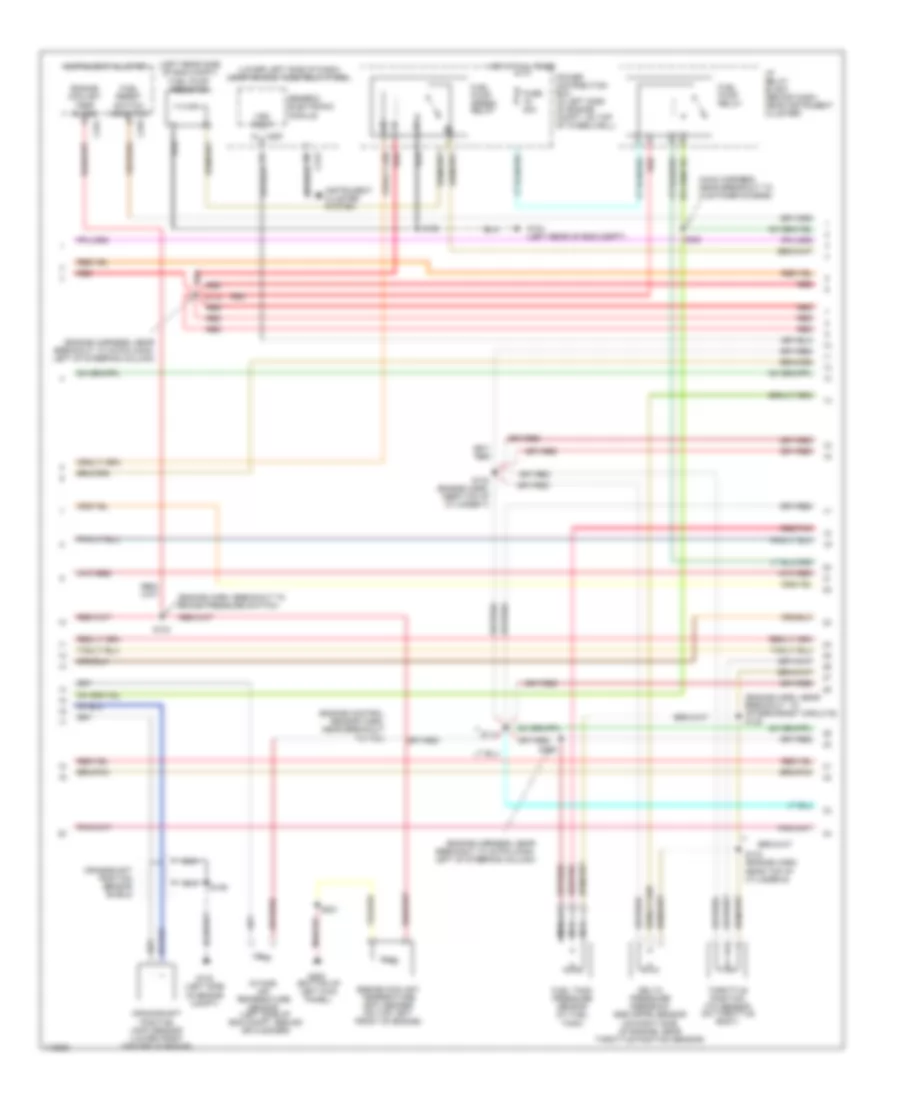
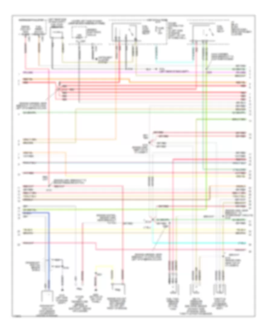
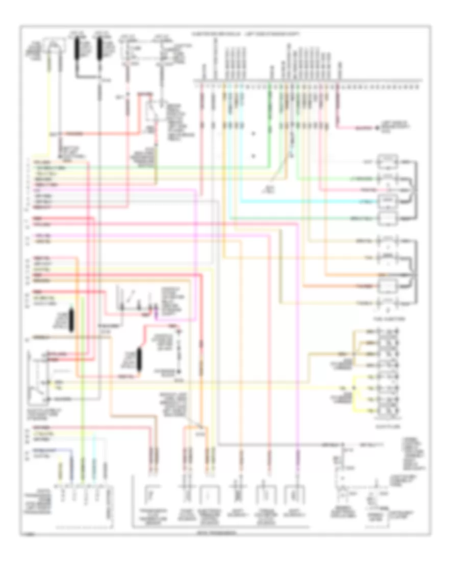
5.4L, Engine Performance Wiring Diagram (1 of 4) for Ford Cab & Chassis F350 Super Duty 1999

List of elements for 5.4L, Engine Performance Wiring Diagram (1 of 4) for Ford Cab & Chassis F350 Super Duty 1999:
- (bottom of left kick panel) g200
- (eng sens harn, right side of eng, above cylinder 3)
- (engine harness, near breakout to power distribution box)
- (left rear corner of eng compt) g104
- (left rear corner of engine compt) g104
- (not used)
- (on left side of engine)
- (on right side of engine)
- 4x4 low ind sw
- 820 ohms
- Ac head press sw
- Air conditioning system
- Body computer system
- C243
- C251
- C253
- Ccs
- Ckp(+)
- Ckp(-)
- Data link (+)
- Data link (-)
- Data link connector (dlc) (partial) (behind center of dash)
- Data output
- Diag grd
- Digital transmission range (dtr) sensor (on left side of transmission)
- Egr sol
- Fpsr cntrl
- Fuel gauge in
- Fuel pump mon
- Fuse 10a
- Fuse 20a
- Fuse 30a
- Hego 12
- Hot at all times
- Hot in run or start
- Iat
- Ign coil 1
- Ign coil 3
- Ign coil 5
- Ign coil 6
- Ignition coils
- Instrument cluster
- Instrument cluster system
- Intake manifold
- Intake manifold tunning valve (on top left side of engine)
- Junction box fuse/relay panel (behind lower left side of dash)
- Maf
- Mil ind
- Nca
- Not used
- O/d off
- Overdrive cancel switch (a/t)
- Pcm power diode
- Pcm power relay
- Power distribution box (in left side of engine compt, on top wheelwell)
- Powertrain control module (pcm) (on left side of firewall)
- Pwr gnd
- R n
- Radio noise capacitor
- Radio noise capacitor 2
- Red
- Reprog pwr
- S102
- S103
- S106
- S120
- S130 (engine harn, near breakout to throttle body conn)
- S135
- S201
- S213
- Shift sol 1
- Shift sol 2
- Tach
- Tcs
- Temp output
- Tft
- To dtr sensor (diagram 4 of 4)
- Tr1
- Tr2
- Tr4
- Trans ctrl ind
- Transmission control indicator lamp
- Vss (-)
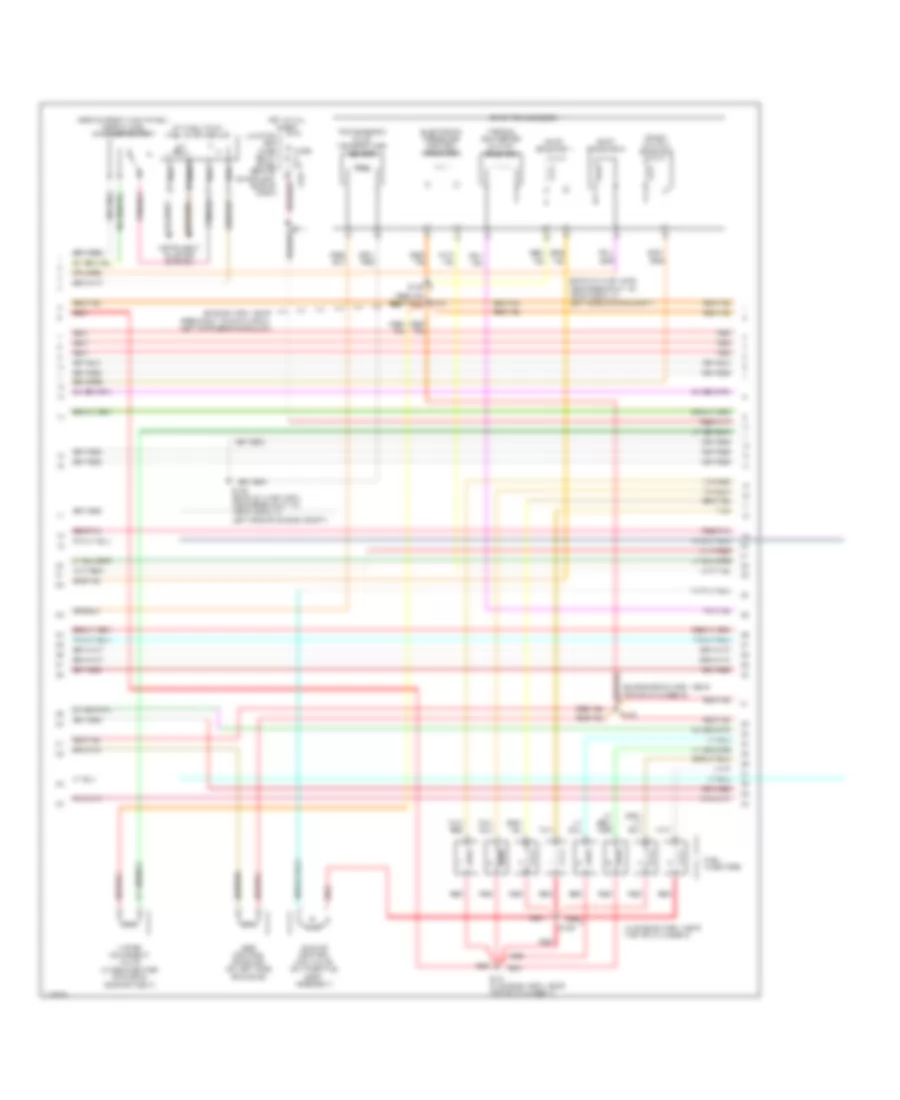
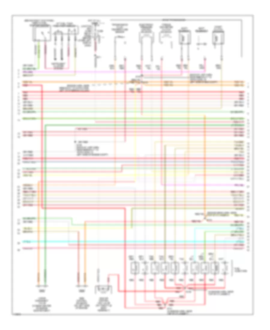
5.4L, Engine Performance Wiring Diagram (2 of 4) for Ford Cab & Chassis F350 Super Duty 1999
List of elements for 5.4L, Engine Performance Wiring Diagram (2 of 4) for Ford Cab & Chassis F350 Super Duty 1999:
- (engine control sensor harn, near breakout to pcm)
- (engine harn, breakout to brake pressure switch)
- (engine harn, near breakout to aftermarket circuits) s128
- (engine harness, near breakout to 40-pin conn, left of steering column)
- (left rear side of eng compt) fuel pump resistor
- (lower left side of dash) junction box fuse/relay panel
- (main harness, near breakout to customer access)
- C251
- C253
- C267
- Crankshaft position (ckp) sensor (lower front center of engine)
- Crankshaft position sensor shield
- Delta pressure feedback egr (dpfe) sensor (on right side of engine, near throttle position sensor)
- Engine coolant temp guage
- Engine coolant temperature (ect) sender (on top left front of engine)
- Fuel pump relay
- Fuel pump speed relay
- Fuel reset switch indicator
- Fuel tank pressure sensor (at fuel tank)
- Fuse 20a
- G102 (left side of engine compt)
- G104 (left rear of eng compt)
- G200 (bottom of left kick panel)
- Generic electronic module
- Hot at all times
- I/p relay block (behind dash, near instrument cluster)
- Instrument cluster
- Instrument cluster system
- Intake air temperature sensor (left side of eng compt, behind air cleaner)
- Nca
- Power distribution box (in left side of engine compt, on top of wheelwell)
- Red
- Red/pnk
- S102
- S104
- S106
- S114
- S123
- S129
- S132 (engine harn, near top of cylinder 7)
- S133 (engine harn, near top of cylinder 6)
- S201
- S226
- Throttle position (tp) sensor (on throttle body)
- Vss input
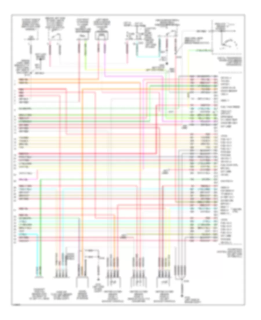
5.4L, Engine Performance Wiring Diagram (3 of 4) for Ford Cab & Chassis F350 Super Duty 1999
List of elements for 5.4L, Engine Performance Wiring Diagram (3 of 4) for Ford Cab & Chassis F350 Super Duty 1999:
- (at fuel tank) fuel pump module
- (backup lamp harn, near breakout to 16-pin conn, in left side of eng compt)
- (behind right kick panel) inertia fuel shut-off switch
- (engine harn, near breakout to 40-pin conn, left of steering column)
- (engine sens harn, near top of cylinder 8)
- (in engine harn, near top of cylinder 3)
- (in rear center of engine compartment)
- 4r100 transmission
- Coast clutch solenoid
- Egr control solenoid (on left side of engine)
- Electronic pressure control solenoid
- Fuel injectors
- Fuse 5a
- Hot at all times
- Idle air control (iac) valve (on throttle body assembly)
- Instrument cluster system
- Junction box fuse/ relay panel (behind lower left side of dash)
- Nca
- Red
- Red/pnk
- S122
- S131 (in engine harn, near top of cylinder 7)
- S134
- S136
- S138
- S139 (backup lamp harn, near breakout to 16-pin conn, in left side of engine compt)
- Shift solenoid 1
- Shift solenoid 2
- Tan
- Tan/ red
- Tan/red
- Torque converter clutch solenoid
- Transmission fluid temperature sensor
- Vapor managment valve
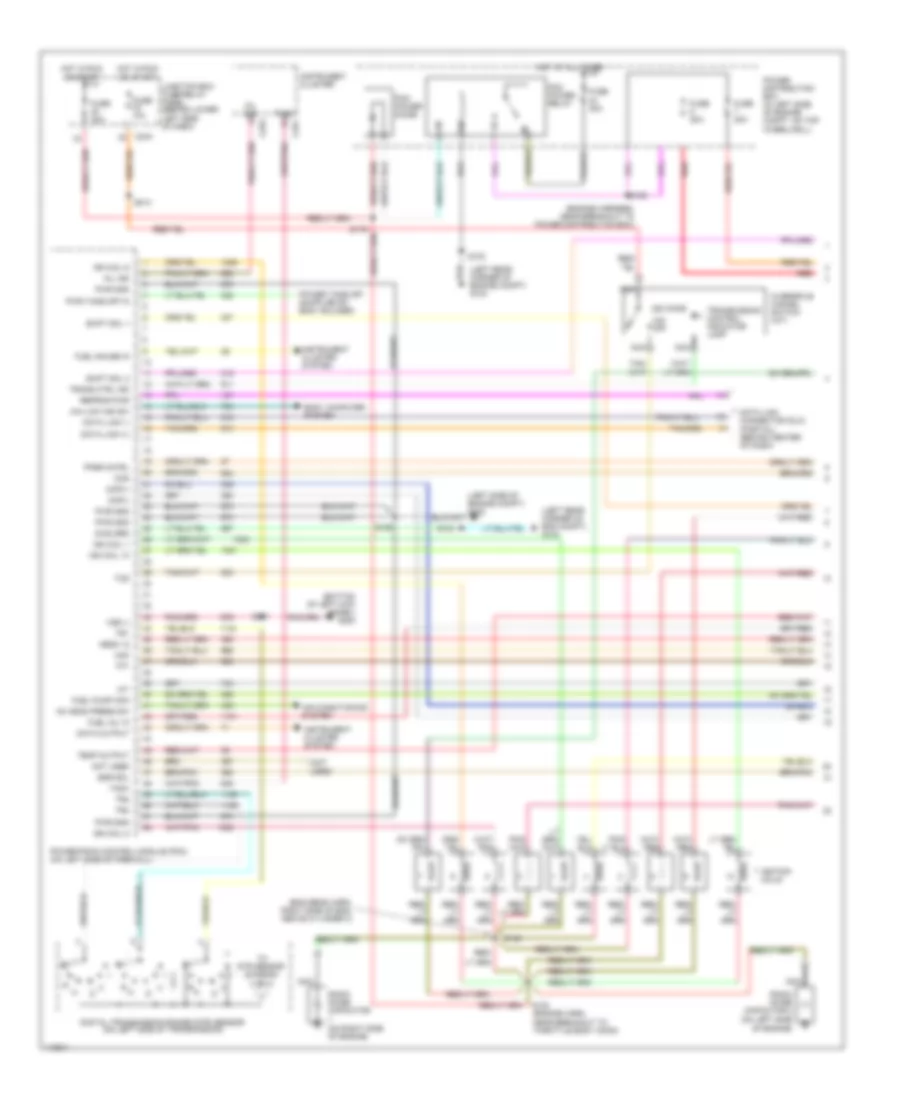
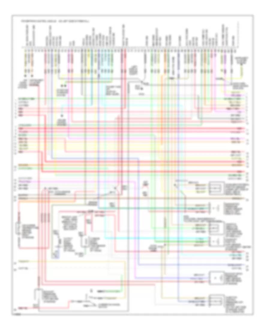
5.4L, Engine Performance Wiring Diagram (4 of 4) for Ford Cab & Chassis F350 Super Duty 1999
List of elements for 5.4L, Engine Performance Wiring Diagram (4 of 4) for Ford Cab & Chassis F350 Super Duty 1999:
- (a/t)
- (above brake pedal) brake pedal position (bpp) switch
- (behind left side of dash, above clutch pedal) clutch pedal position switch (m/t)
- (eng harn, near breakout to brake press switch)
- (engine harn, near breakout to 16-pin conn, left side of eng compt) s115
- (in right side of engine compt) speed control servo/amplifier assembly
- (left rear side of engine compartment) canister vent solenoid
- (m/t)
- (not used)
- (top front of engine) cylinder head temperature (cht) sensor
- 5v ref volt
- Anti-lock brakes system
- Bpp sw
- Cam pos in
- Camshaft position sensor (cmp) (on front of of left cyl head)
- Canister vent
- Cyl head temp
- Digital transmission range (dtr) sensor (left side of transmission)
- Dpfe sens
- Epc sol
- From dtr sensor (diagram 1 of 4)
- Fuel inj 1
- Fuel inj 2
- Fuel inj 3
- Fuel inj 4
- Fuel inj 5
- Fuel inj 6
- Fuel inj 7
- Fuel inj 8
- Fuel pump ctrl
- Fuel tank press
- Fuse 15a
- Fuse 5a
- G102 (left side of eng compt)
- G102 (left side of engine compt)
- G200 (bottom of left kick panel)
- Heated oxygen sensor (ho2s) 11 (on right exhaust manifold)
- Heated oxygen sensor (ho2s) 12 (rear of catalytic converter)
- Heated oxygen sensor (ho2s) 21 (on left exhaust manifold)
- Heater ctrl
- Hego 11
- Hego 12
- Hego 21
- Hot at all times
- Hot in start
- Iac sol
- Ign coil 2
- Ign coil 4
- Ign coil 7
- Ign coil 8
- Junction box fuse/ relay panel (behind lower left side of dash)
- Kap b(+)
- Knock sensor
- Knock sensor (on rear of engine)
- Knock sensor shield
- Maf sens in
- Mass air flow (maf) sensor (in left front of eng compt)
- Nca
- Not used
- Powertrain control module (pcm) (on left side of firewall)
- Pwr gnd
- Red
- Red/pnk
- S106
- S108
- S201
- Sig return
- Tan
- Tan/red
- Tcc sol
- Tp sens in
- Tr3a (a/t) cpp (m/t)
- Vapor valve
- Vpwr
- Vss (+)
- Vss input
6.8L
6.8L, Engine Performance Wiring Diagram (1 of 4) for Ford Cab & Chassis F350 Super Duty 1999
List of elements for 6.8L, Engine Performance Wiring Diagram (1 of 4) for Ford Cab & Chassis F350 Super Duty 1999:
- (bottom of left kick panel) g200
- (eng sens harn, right side of eng, above cylinder 3)
- (engine harness, near breakout to power distribution box)
- (left rear corner of eng compt) g104
- (left rear corner of engine compt) g104
- (not used)
- (on left side of engine)
- (on right side of engine)
- 4x4 low ind sw
- 820 ohms
- Ac head press sw
- Air conditioning system
- Body computer system
- C243
- C251
- C253
- Ccs
- Ckp(+)
- Ckp(-)
- Data link (+)
- Data link (-)
- Data link connector (dlc) (partial) (behind center of dash)
- Data output
- Diag grd
- Digital transmission range (dtr) sensor (on left side of transmission)
- Egr sol
- Fpsr cntrl
- Fuel gauge in
- Fuel inj 10
- Fuel pump mon
- Fuse 10a
- Fuse 20a
- Fuse 30a
- Hego 12
- Hot at all times
- Hot in run or start
- Iat
- Ign coil 1
- Ign coil 10
- Ign coil 5
- Ign coil 6
- Ignition coils
- Instrument cluster
- Instrument cluster system
- Junction box fuse/relay panel (behind lower left side of dash)
- Maf
- Mil ind
- Nca
- Not used
- O/d off
- Overdrive cancel switch (a/t)
- Pcm power diode
- Pcm power relay
- Power distribution box (in left side of engine compt, on top wheelwell)
- Powertrain control module (pcm) (on left side of firewall)
- Pwr gnd
- Pwr take off in
- R n
- Radio noise capacitor
- Radio noise capacitor 2
- Red
- Red/
- Reprog pwr
- S102
- S103
- S106
- S120
- S130 (engine harn, near breakout to throttle body conn)
- S135
- S201
- S213
- Shift sol 1
- Shift sol 2
- Tach
- Tcs
- Temp output
- Tft
- To dtr sensor (diagram 4 of 4)
- Tr1
- Tr2
- Tr4
- Trans ctrl ind
- Transmission control indicator lamp
- Vss (-)
6.8L, Engine Performance Wiring Diagram (2 of 4) for Ford Cab & Chassis F350 Super Duty 1999
List of elements for 6.8L, Engine Performance Wiring Diagram (2 of 4) for Ford Cab & Chassis F350 Super Duty 1999:
- (engine control sensor harn, near breakout to pcm)
- (engine harn, breakout to brake pressure switch)
- (engine harn, near breakout to aftermarket circuits) s128
- (engine harness, near breakout to 40-pin conn, left of steering column)
- (left rear side of eng compt) fuel pump resistor
- (lower left side of dash) junction box fuse/relay panel
- (main harness, near breakout to customer access)
- C251
- C253
- C267
- Crankshaft position (ckp) sensor (lower front center of engine)
- Crankshaft position sensor shield
- Delta pressure feedback egr (dpfe) sensor (on right side of engine, near throttle position sensor)
- Engine coolant temp guage
- Engine coolant temperature (ect) sender (on top left front of engine)
- Fuel pump relay
- Fuel pump speed relay
- Fuel reset switch indicator
- Fuel tank pressure sensor (at fuel tank)
- Fuse 20a
- G102 (left side of engine compt)
- G104 (left rear of eng compt)
- G200 (bottom of left kick panel)
- Generic electronic module
- Hot at all times
- I/p relay block (behind dash, near instrument cluster)
- Instrument cluster
- Instrument cluster system
- Intake air temperature sensor (left side of eng compt, behind air cleaner)
- Nca
- Power distribution box (in left side of engine compt, on top of wheelwell)
- Red
- Red/pnk
- S102
- S104
- S106
- S114
- S123
- S129
- S132 (engine harn, near top of cylinder 7)
- S133 (engine harn, near top of cylinder 6)
- S201
- S226
- Throttle position (tp) sensor (on throttle body)
- Vss input
6.8L, Engine Performance Wiring Diagram (3 of 4) for Ford Cab & Chassis F350 Super Duty 1999
List of elements for 6.8L, Engine Performance Wiring Diagram (3 of 4) for Ford Cab & Chassis F350 Super Duty 1999:
- (at fuel tank) fuel pump module
- (backup lamp harn, near breakout to 16-pin conn, in left side of eng compt)
- (behind right kick panel) inertia fuel shut-off switch
- (engine harn, near breakout to 40-pin conn, left of steering column)
- (engine sens harn, near top of cylinder 8)
- (in engine harn, near top of cylinder 3)
- (in rear center of engine compartment)
- 4r100 transmission
- Coast clutch solenoid
- Egr control solenoid (on left side of engine)
- Electronic pressure control solenoid
- Fuel injectors
- Fuse 5a
- Hot at all times
- Idle air control (iac) valve (on throttle body assembly)
- Instrument cluster system
- Junction box fuse/ relay panel (behind lower left side of dash)
- Nca
- Red
- Red/pnk
- S122
- S131 (in engine harn, near top of cylinder 7)
- S134
- S136
- S138
- S139 (backup lamp harn, near breakout to 16-pin conn, in left side of engine compt)
- Shift solenoid 1
- Shift solenoid 2
- Tan
- Tan/ red
- Tan/red
- Torque converter clutch solenoid
- Transmission fluid temperature sensor
- Vapor managment valve
6.8L, Engine Performance Wiring Diagram (4 of 4) for Ford Cab & Chassis F350 Super Duty 1999
List of elements for 6.8L, Engine Performance Wiring Diagram (4 of 4) for Ford Cab & Chassis F350 Super Duty 1999:
- (a/t)
- (above brake pedal) brake pedal position (bpp) switch
- (behind left side of dash, above clutch pedal) clutch pedal position switch (m/t)
- (eng harn, near breakout to brake press switch)
- (engine harn, near breakout to 16-pin conn, left side of eng compt) s115
- (in right side of engine compt) speed control servo/amplifier assembly
- (left rear side of engine compartment) canister vent solenoid
- (m/t)
- (top front of engine) cylinder head temperature (cht) sensor
- 5v ref volt
- Anti-lock brakes system
- Bpp sw
- Cam pos in
- Camshaft position sensor (cmp) (on front of of left cyl head)
- Canister vent
- Cyl head temp
- Digital transmission range (dtr) sensor (left side of transmission)
- Dpfe sens
- Epc sol
- From dtr sensor (diagram 1 of 4)
- Fuel inj 1
- Fuel inj 2
- Fuel inj 3
- Fuel inj 4
- Fuel inj 5
- Fuel inj 6
- Fuel inj 7
- Fuel inj 8
- Fuel inj 9
- Fuel pump ctrl
- Fuel tank press
- Fuse 15a
- Fuse 5a
- G102 (left side of eng compt)
- G102 (left side of engine compt)
- G200 (bottom of left kick panel)
- Heated oxygen sensor (ho2s) 11 (on right exhaust manifold)
- Heated oxygen sensor (ho2s) 12 (rear of catalytic converter)
- Heated oxygen sensor (ho2s) 21 (on left exhaust manifold)
- Heater ctrl
- Hego 11
- Hego 12
- Hego 21
- Hot at all times
- Hot in start
- Iac sol
- Ign coil 2
- Ign coil 3
- Ign coil 4
- Ign coil 7
- Ign coil 8
- Ign coil 9
- Junction box fuse/ relay panel (behind lower left side of dash)
- Kap b(+)
- Knock sensor
- Knock sensor (on rear of engine)
- Knock sensor shield
- Maf sens in
- Mass air flow (maf) sensor (in left front of eng compt)
- Nca
- Powertrain control module (pcm) (on left side of firewall)
- Pwr gnd
- Red
- Red/pnk
- S106
- S108
- S201
- Sig return
- Tan
- Tan/red
- Tcc sol
- Tp sens in
- Tr3a (a/t) cpp (m/t)
- Vapor valve
- Vpwr
- Vss (+)
- Vss input
7.3L DI TURBO DIESEL
7.3L DI Turbo Diesel, Engine Performance Wiring Diagram (1 of 3) for Ford Cab & Chassis F350 Super Duty 1999
List of elements for 7.3L DI Turbo Diesel, Engine Performance Wiring Diagram (1 of 3) for Ford Cab & Chassis F350 Super Duty 1999:
- (behind lower right side of dash)
- (below left side of dash) data link connector
- (eng harn, near breakout to 40-pin conn, left side of dash)
- (left side of engine compt)
- (main harn, near breakout to 16-pin conn, center of dash)
- (on left side of firewall) powertrain control module
- (pia engine harness)
- 224 (a/t) 306 (m/t)
- 4x4 low range sw
- A/t
- Aux tach feed
- Auxiliary powertrain control module (apcm)
- Brake press sw
- Brake pressure switch
- Brake warning ind
- Bus (+)
- Bus (-)
- C243
- C250
- C251
- C253
- Cam pos sens
- Ccs sol
- Clutch pedal position (cpp) switch (behind left side of dash, above clutch pedal)
- Diesel fuel pump motor (near fuel tank)
- Dtr-tr1
- Ebp sens
- Engine oil temperature (eot) sensor (top front of engine)
- Eot
- Fuel heater (on center of engine)
- Fuel htr
- Fuel pump pwr
- Fuel pump relay
- Fuel reset ind
- Fuse 10a
- Fuse 20a
- Fuse 30a
- G104 (left rear of engine compt)
- G200 (bottom of left kick panel)
- Gen pwr sw
- Gen scan tool in
- Glow plug monitor
- Hot at all times
- Hot in run or start
- I/p relay box
- Iat
- Idle validation sw
- Idle validation switch (open at idle) (lower left side of dash)
- Idm power relay
- Inertia fuel shutoff switch (behind right kick panel)
- Injection pressure regulator (top center of engine)
- Instrument cluster
- Instrument cluster system
- Intake air temperature sensor (left side of engine compt, behind air cleaner)
- Junction box fuse/ relay panel
- Lo current sense
- M/t
- Mal- function ind
- Mil ind
- Nca
- Neutral gear sw
- Not used
- Pcm diode
- Pcm power relay
- Power distribution box
- Red
- Red s123
- S102
- S103
- S141 (engine harn, near breakout to pcm conn)
- S154
- S158
- S179
- S213
- S217
- S219
- S221
- S250
- Speed/tach grd
- Ss1
- Ss2
- Starting/ charging system
- Tcil
- Tcs(a/t)/cpp(m/t)
- Tft
- Tp sens
- Wait to start ind
- Wastegate control solenoid (in center of engine)
- Water in fuel ind
7.3L DI Turbo Diesel, Engine Performance Wiring Diagram (2 of 3) for Ford Cab & Chassis F350 Super Duty 1999
List of elements for 7.3L DI Turbo Diesel, Engine Performance Wiring Diagram (2 of 3) for Ford Cab & Chassis F350 Super Duty 1999:
- (backup lamp harn, near breakout to 16-pin conn, left side of eng compt)
- (eng ctrl harn)
- (engine harness)
- (in pia engine harn)
- (in pia engine harness)
- (left side of engine compt)
- (main harn, near air bag diag mod)
- (on left side of firewall)
- A/c head pres sw
- Accelerator pedal position sensor (under left side of dash, above brake pedal)
- Accl pos sens
- Act sens
- Air charge temperature sensor (center front of engine)
- Air condi- tioning system
- Baro sens
- Barometric pressure (baro) sensor (below left side of dash)
- Bpp sw
- Camshaft position (cmp) sensor (lower front center of engine)
- Charge ind
- Cid sig
- Cmp rtn
- Cruise control system
- Data output link
- Diesel elect drv
- Dtr-tr2
- Dtr-tr3a
- Dtr-tr4
- Epc sol
- Epr
- Exhaust back pressure (ebp) sensor (center rear of engine)
- Exhaust pressure regulator (top center of engine)
- Fuel deliv sig
- Fuel pump rly
- Fuel pump sender
- G102
- Gen pwr
- Glow plug ctrl
- Icp sens
- Idm enable out
- Injection control pressure (icp) sensor (on top left side of engine, right of alternator)
- Instrument cluster system
- Ipr sens
- Manifold absolute pressure (map) sensor (on right side of firewall)
- Map sens
- Nca
- Not used
- Oss sens
- Output shaft speed sensor (on top of trans)
- Overdrive cancel switch
- Pcm to rly
- Power take off (supp by body bldr)
- Powertrain control module
- Pwr
- Pwr gnd
- Pwr in
- Red
- S106
- S114
- S128
- S139
- S151
- S153
- S208
- S222 (main harn, near breakout to 2-pin conn, left side of dash)
- Sig rtn
- Speed ctrl sw
- Starting/ charging system
- Take off pwr in
- Tcc
- Tcil
- Tcs
- Tss sens
- Turbine shaft speed (tss) sensor (on top of trans)
- Vref
- Vss (+)
- Wait to start ind
- Wcs sol
7.3L DI Turbo Diesel, Engine Performance Wiring Diagram (3 of 3) for Ford Cab & Chassis F350 Super Duty 1999
List of elements for 7.3L DI Turbo Diesel, Engine Performance Wiring Diagram (3 of 3) for Ford Cab & Chassis F350 Super Duty 1999:
- (backup lamp harn, near breakout to 16-pin conn left side of eng compt)
- (bottom of left kick panel) g202
- (left side of engine compt)
- (left side of engine compt) g102
- (on engine block)
- (right side of eng compt)
- 4r100 transmission
- Brake pedal position switch (behind left side of dash, above brake pedal)
- C241
- C243
- C253
- Cid sig in
- Coast clutch solenoid
- Digital transmission range (dtr) sensor (left side of transmission)
- Elect feed back sig
- Electronic pressure control solenoid
- Fuel delivery sig
- Fuel gauge sender (at fuel tank)
- Fuel inj feed
- Fuel injector 1
- Fuel injector 2
- Fuel injector 3
- Fuel injector 4
- Fuel injector 5
- Fuel injector 6
- Fuel injector 7
- Fuel injector 8
- Fuel injectors
- Fuse 5a
- G132
- Generic electronic module (gem)
- Glow plug relay (top right side of engine)
- Glow plugs
- Hot at all times
- Inj shield gnd
- Injector driver module
- Instrument cluster
- Junction box fuse/ relay panel
- Junction box fuse/relay panel
- Manifold intake air heater (58 amp)
- Manifold intake air heater relay (center of engine compt)
- Nca
- P, 2, 1
- P, r, 2
- P, r, 2, 1
- P, r, n
- Pwr gnd
- Pwr in
- Red
- S108 (eng harn near brake pressure switch)
- S115
- S138
- S148
- S149
- S155 (pia engine harness)
- S156 (pia engine harness)
- S211
- Shift solenoid 1
- Shift solenoid 2
- Sig rtn
- Signal return
- Speed control servo/ amplifier assembly
- Speedo- meter
- Tan
- Tan/red
- Torque converter clutch solenoid
- Transmission fluid temperature sensor