ENGINE PERFORMANCE
5.4L
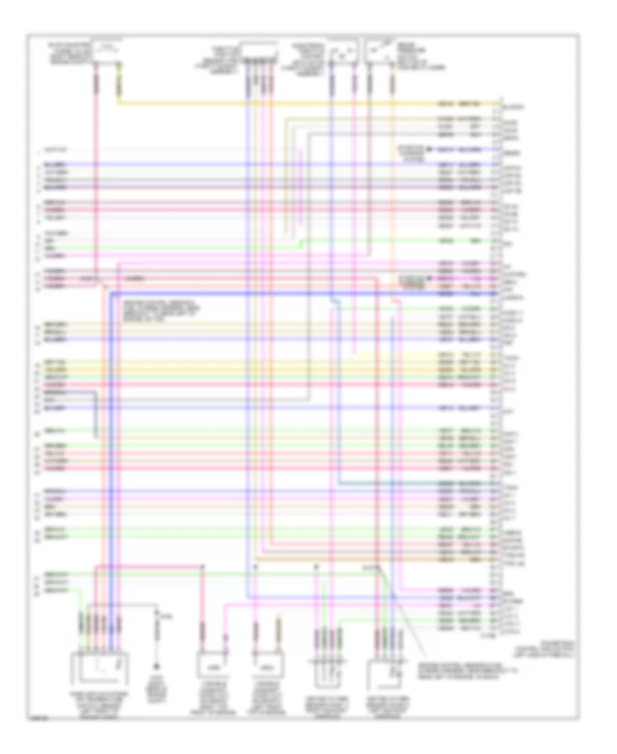
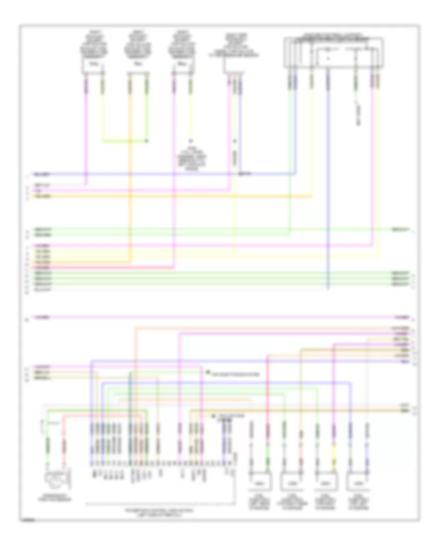
5.4L, Engine Performance Wiring Diagram (1 of 6) for Ford Cab & Chassis F350 Super Duty 2010

List of elements for 5.4L, Engine Performance Wiring Diagram (1 of 6) for Ford Cab & Chassis F350 Super Duty 2010:
- Anti-lock brakes system
- App1
- App2
- App3
- Apprtn
- Apprtn2
- Appvref
- Appvref2
- Battery junction box (bjb) (left rear of engine compt)
- Bpp
- C175b
- C2280b
- Canv
- Cat15
- Cbb71
- Cbb76
- Ccb08
- Cdb08
- Cdc12
- Ce114
- Ce237
- Ce326
- Ce903
- Ce904
- Ce912
- Ce913
- Ce914
- Ce924
- Cet21
- Cls05
- Cls28
- Clutch pedal position switch (m/t) (left side of dash)
- Computer data lines system
- Cpp bt
- Cpp tt
- Cruise control system
- Cto
- Evap canister vent solenoid (left rear side of frame)
- Exterior lights system
- Fpc
- Fpm
- Ftp
- Ftpref
- Fuse 10a
- Fuse 15a
- Fuse 20a
- Fuse 30a
- Fuse 5a
- G103 (right rear of engine compt)
- G106 (right rear of engine compt)
- Gd113
- Gd164
- Gnd
- Hot at all times
- Hot in run or start
- Hscan bus+
- Hscan bus-
- Isp r
- Kapwr
- Le136
- Le137
- Le230
- Nca
- Neutral
- Park
- Pcm power relay
- Pcmrc
- Peps
- Powertrain control module (pcm) (left side of firewall)
- Pto
- Pto rpm
- Ptoil
- Ptoir
- Re136
- Re137
- Re407
- Res08
- Reversing lamp relay
- Rlc
- S102 (engine control sensor harness, near breakout to right rear of engine compt)
- S154
- S158 (engine control sensor harness, near breakout to left front corner of vehicle)
- S162
- S227
- Sbb36
- Sccs
- Sccsrtn
- Sigrtn
- Smart junction box (right side of dash)
- Smc
- Tcs
- Tow haul switch (top of steering column)
- Vdb04
- Vdb05
- Ve225
- Ve518
- Ve701
- Ve702
- Ve703
- Ve822
- Ve922
- Ves10
- Vmc05
- Vpwr1-a
- Vpwr1-b
- Vsc
- Vsout
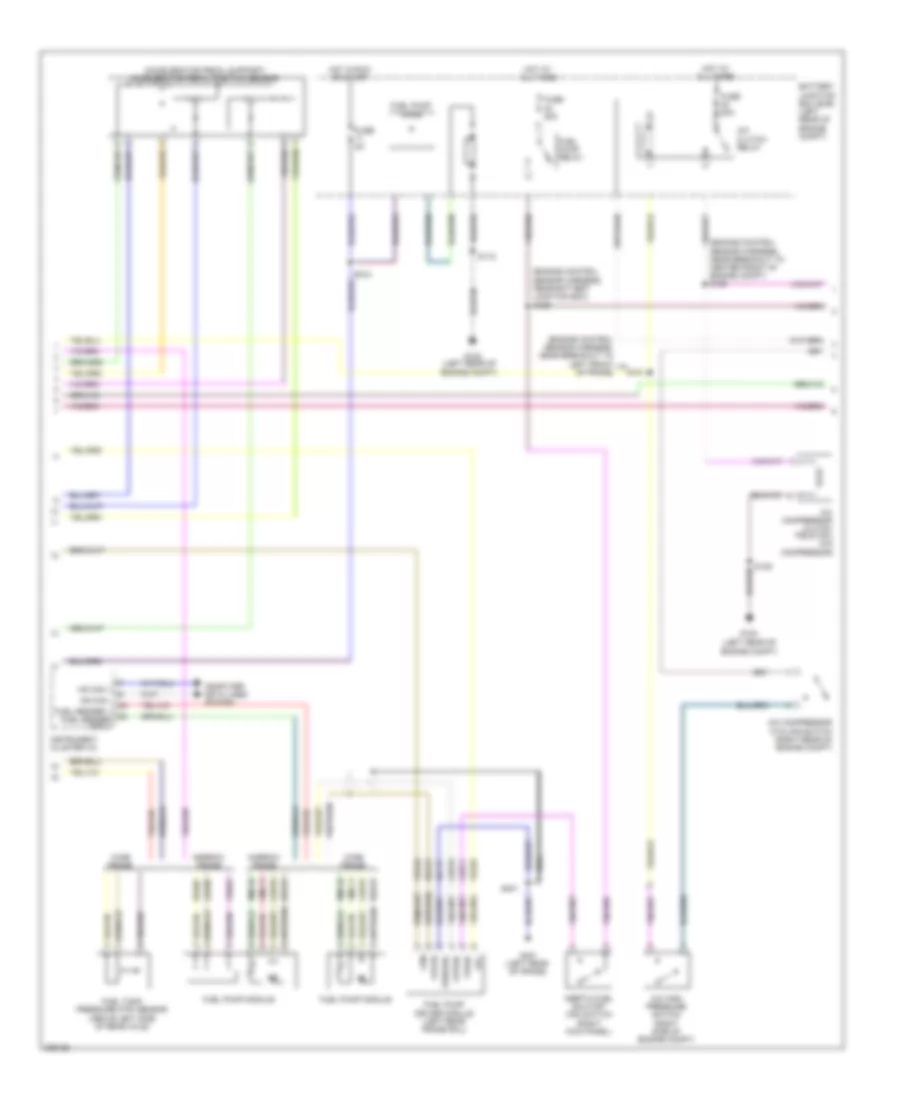
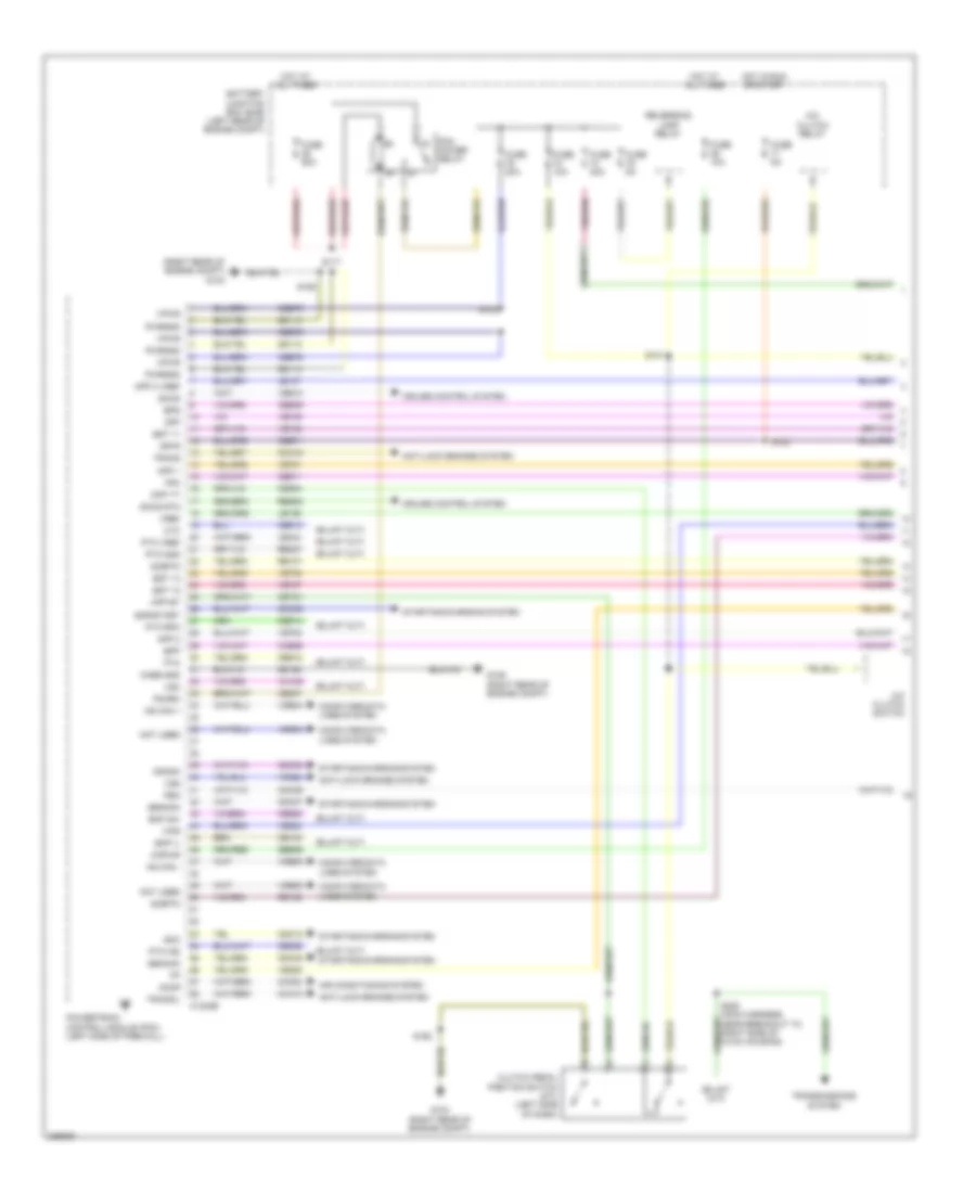
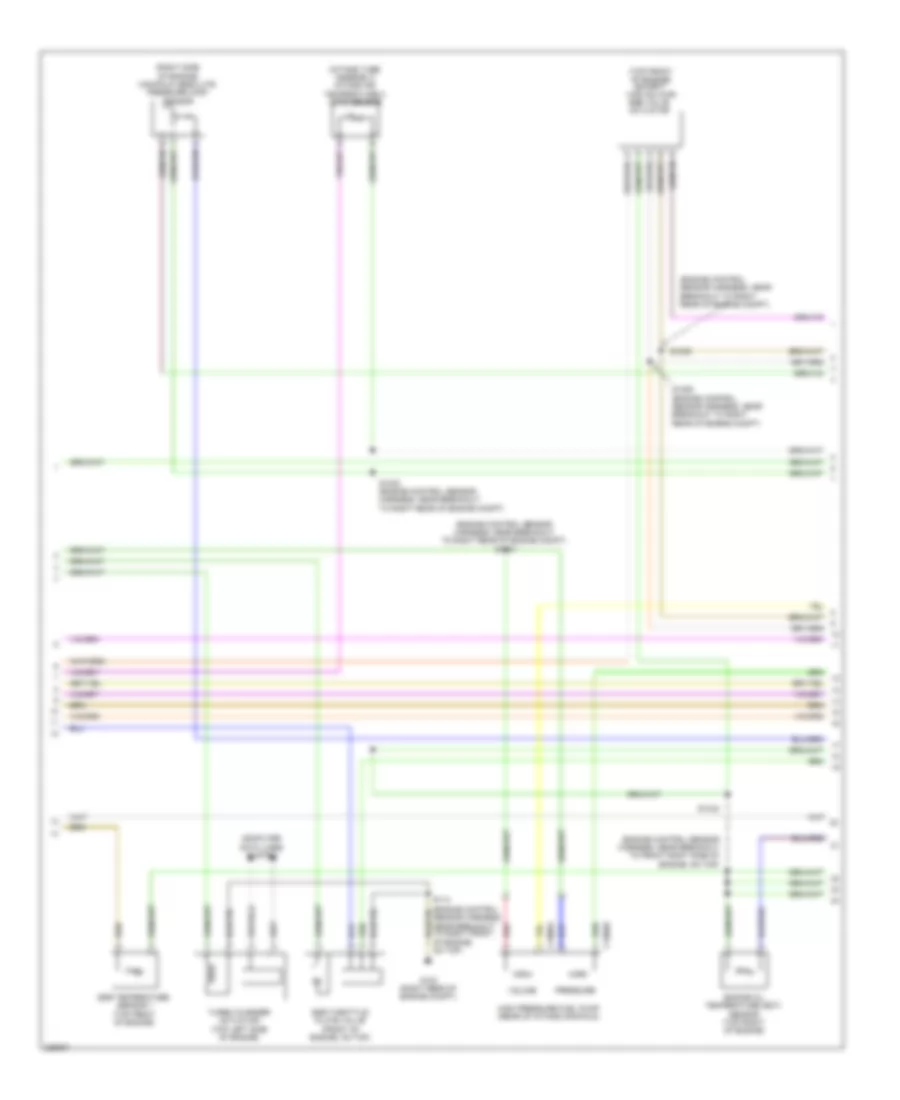
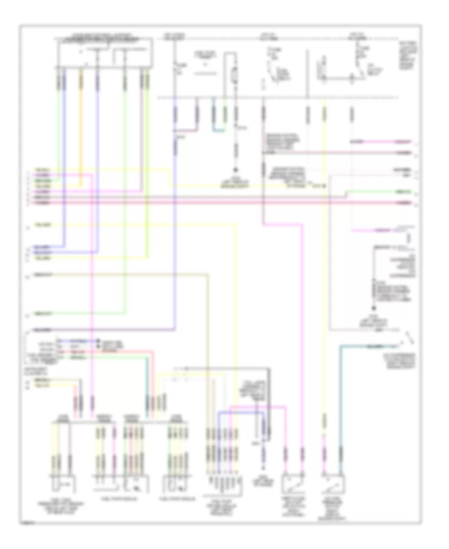
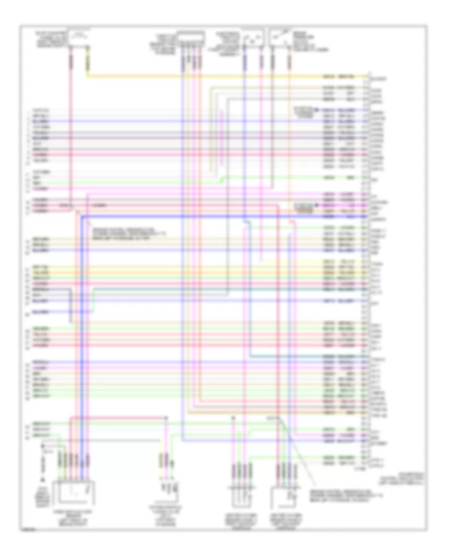
5.4L, Engine Performance Wiring Diagram (2 of 6) for Ford Cab & Chassis F350 Super Duty 2010
List of elements for 5.4L, Engine Performance Wiring Diagram (2 of 6) for Ford Cab & Chassis F350 Super Duty 2010:
- (accelerator pedal support) accelerator pedal position sensor
- (engine control sensor harness, near battery junction box) s156
- (engine control sensor harness, near breakout to center front of engine compt) s120
- (engine control sensor harness, near breakout to left front of frame)
- (left rear of engine compt)
- A/c clutch relay
- A/c compressor clutch field coil (a/c compressor)
- A/c compressor cycling switch (right rear of engine compt)
- A/c high pressure switch (right side of engine compt)
- Battery junction box (bjb) (left rear of engine compt)
- Ce515
- Ce911
- Computer data lines system
- Fpc
- Fpm
- Fppwr
- Fprtn
- Fuel pump diode
- Fuel pump driver module (left rear frame rail)
- Fuel pump module
- Fuel pump relay
- Fuel sender 1 fuel sender rtn 1
- Fuel tank pressure (ftp) sensor (above left side of rear axle)
- Fuse 20a
- Fuse 5a
- G108
- G108 (left rear of engine compt)
- G401 (left rear of frame)
- Gd117
- Hot at all times
- Hot in run or start
- Hs can +
- Hs can -
- Inertia fuel shutoff (ifs) switch (right kick panel)
- Instrument cluster (ic)
- Le230
- Narrow frame
- Nca
- Pwrgrd
- Re407
- Re515
- Rmc32
- S101
- S115
- S123
- S128
- S401
- Ve225
- Ve518
- Ve922
- Vmc11
- Vpwr
- Wide frame
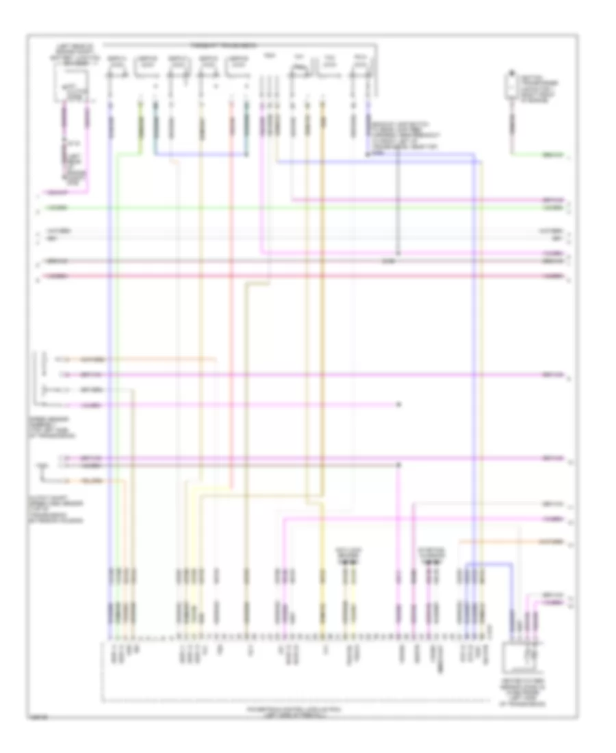
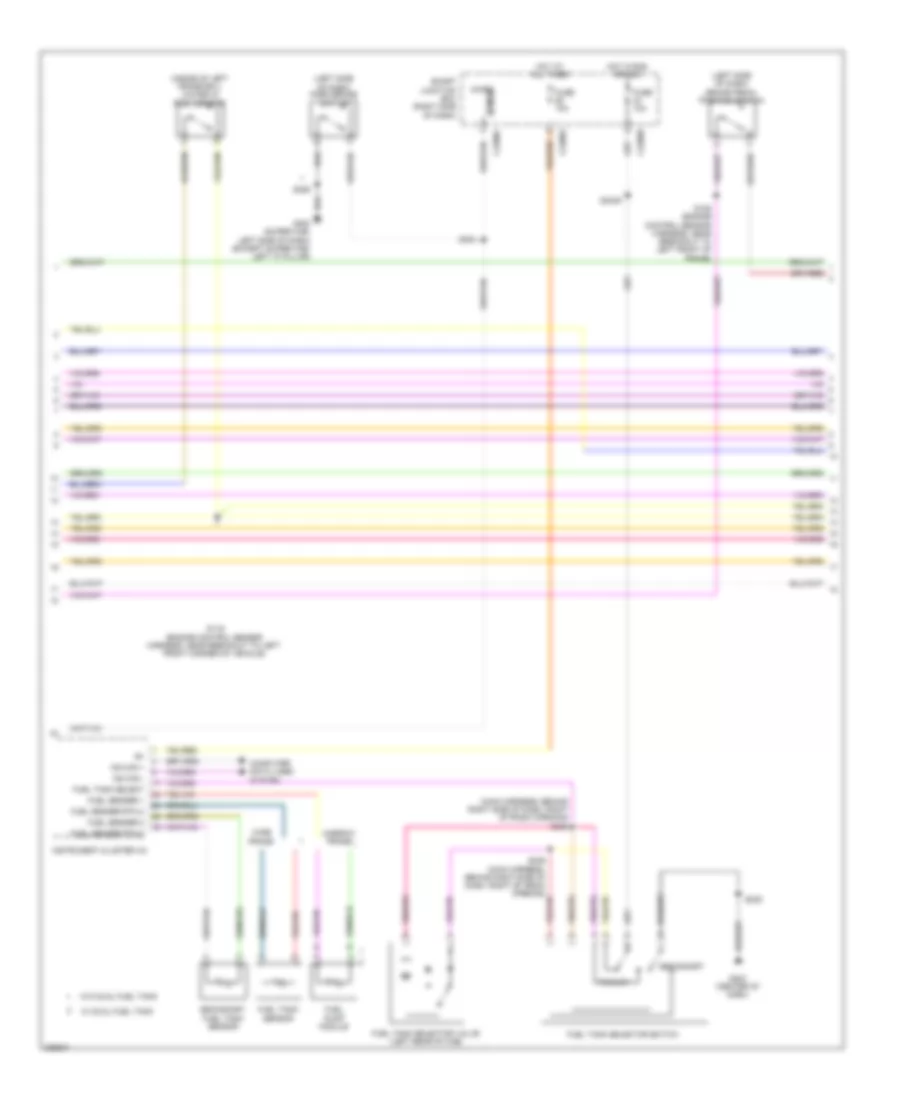
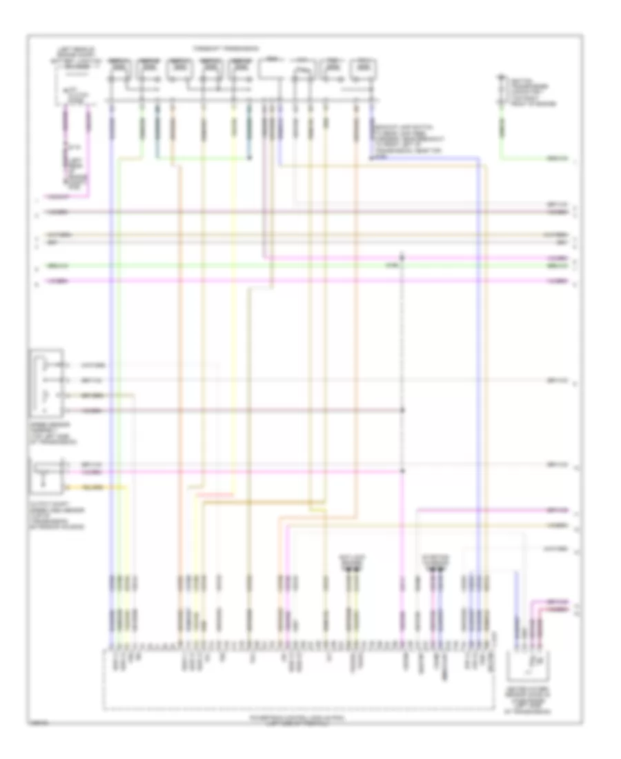
5.4L, Engine Performance Wiring Diagram (3 of 6) for Ford Cab & Chassis F350 Super Duty 2010
List of elements for 5.4L, Engine Performance Wiring Diagram (3 of 6) for Ford Cab & Chassis F350 Super Duty 2010:
- (backup lamp switch to rear lamp feed harness, near breakout to front left of transmission, near top) s194
- (left rear of engine compt) battery junction box (bjb)
- (left rear of engine compt) g108
- A/c clutch diode
- Anti-lock brakes system
- C175t
- Cca10
- Cca15
- Cdc35
- Cdc38
- Ce233
- Ce234
- Cet05
- Cet06
- Cet07
- Cet08
- Cet09
- Cet22
- Cet25
- Cet49
- Cet50
- Crank
- Heated oxygen sensor (ho2s) 22 (wide frame) (left side of transmission)
- Ho2s 12
- Ho2s 22
- Htr 12
- Htr 22
- Ignition transformer capacitor 1 (right front of engine)
- Iss
- Le111
- Lpc
- Oss
- Output shaft speed (oss) sensor (top of transmission extension housing)
- Pc-a
- Powertrain control module (pcm) (left side of firewall)
- Re406
- Ret04
- Ret24
- S115
- S196
- Sig rtn
- Sigrtn
- Smr/start
- Speed sensor assembly (top left side of transmission)
- Sspc a
- Sspc b
- Sspc c
- Sspc d
- Sspc e
- Sspc-a
- Sspc-b
- Sspc-c
- Sspc-d
- Sspc-e
- Starting/ charging system
- Tcc
- Tft
- Torqshift transmission
- Tr p
- Tr-p
- Tracs
- Tracsil
- Tspc
- Tss
- Vbpwr
- Ve730
- Ve733
- Ve744
- Vet27
- Vet33
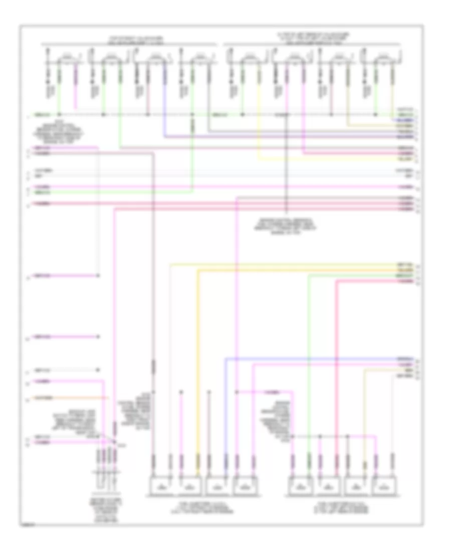
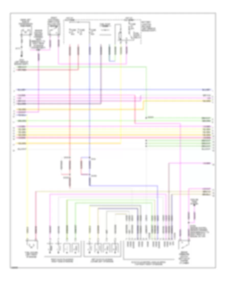
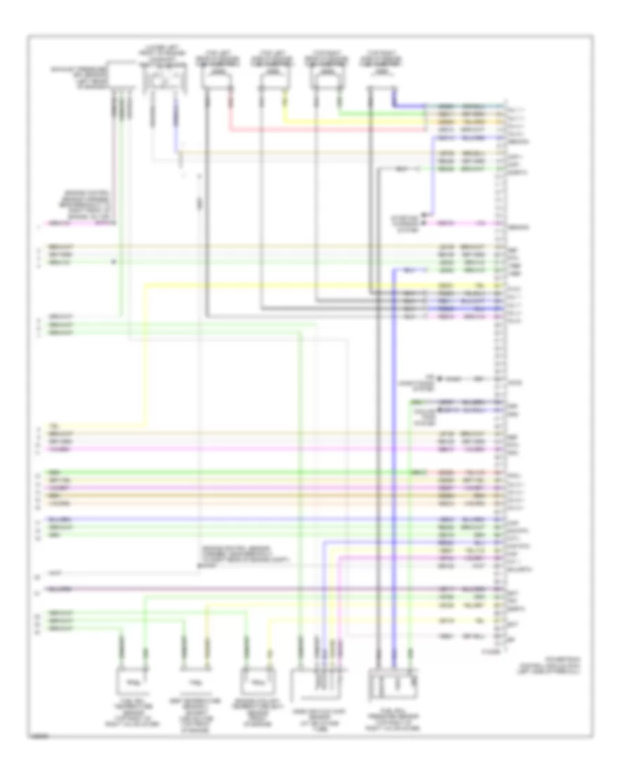
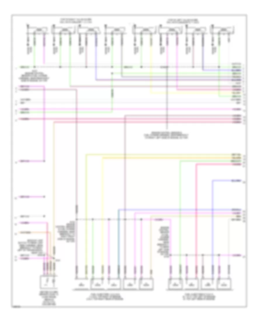
5.4L, Engine Performance Wiring Diagram (4 of 6) for Ford Cab & Chassis F350 Super Duty 2010
List of elements for 5.4L, Engine Performance Wiring Diagram (4 of 6) for Ford Cab & Chassis F350 Super Duty 2010:
- (8: top of left rear of valve cover) (5, 6 & 7: top of left valve cover) coil on plugs (cop) 5, 6, 7 & 8
- (backup lamp switch to rear lamp feed harness, near breakout to front left of transmission, near top) s183
- (engine control sensor & fuel charge harness, near breakout to rear left side of engine, on top)
- (engine control sensor & fuel charge harness, near breakout to rear right of engine, on top) s108
- (top of right valve cover) coil on plugs (cop) 1, 2, 3 & 4
- Fuel injectors 1,2,3 & 4 (1 & 2: top right of engine) (3 & 4: top right rear of engine)
- Fuel injectors 5,6,7 & 8 (5, 6 & 7: top left of engine) (8: top left rear of engine)
- Heated oxygen sensor (ho2s) 12 (wide frame) (at rear of catalytic converter)
- Nca
- Plug spark
- S127 (engine control sensor & fuel charge harness, near breakout to rear right side of engine, on top)
- S132 (engine control sensor & fuel charge harness, near breakout to right front side of engine, on top)
- S135
- S181
- Spark plug
5.4L, Engine Performance Wiring Diagram (5 of 6) for Ford Cab & Chassis F350 Super Duty 2010
List of elements for 5.4L, Engine Performance Wiring Diagram (5 of 6) for Ford Cab & Chassis F350 Super Duty 2010:
- (engine control sensor & fuel charge harness, near breakout to right front of engine, on top)
- (left front of engine) camshaft position (ckp) sensor 2
- (right front of engine) camshaft position (ckp) sensor 1
- (top left rear of engine) knock sensor 2
- Crankshaft position (cmp) sensor (lower right side of engine)
- Cylinder head temperature (rear of block, under intake)
- Fuel rail pressure/ temperature sensor (top left of intake manifold)
- Ignition transformer capacitor 2 (top left front of engine)
- Knock sensor 1 (near rear of intake manifold)
- Nca
- S133 (engine control sensor & fuel charge harness, near breakout to right front of engine, on top)
- S134
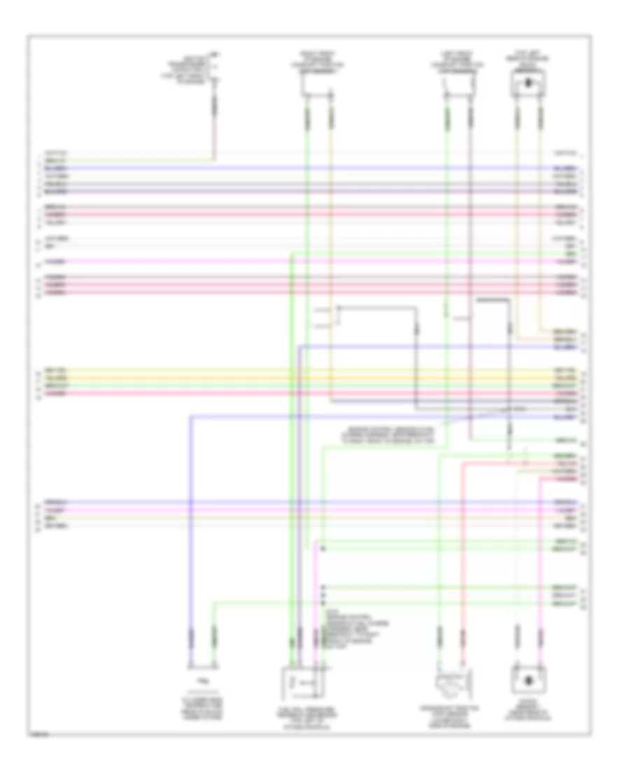
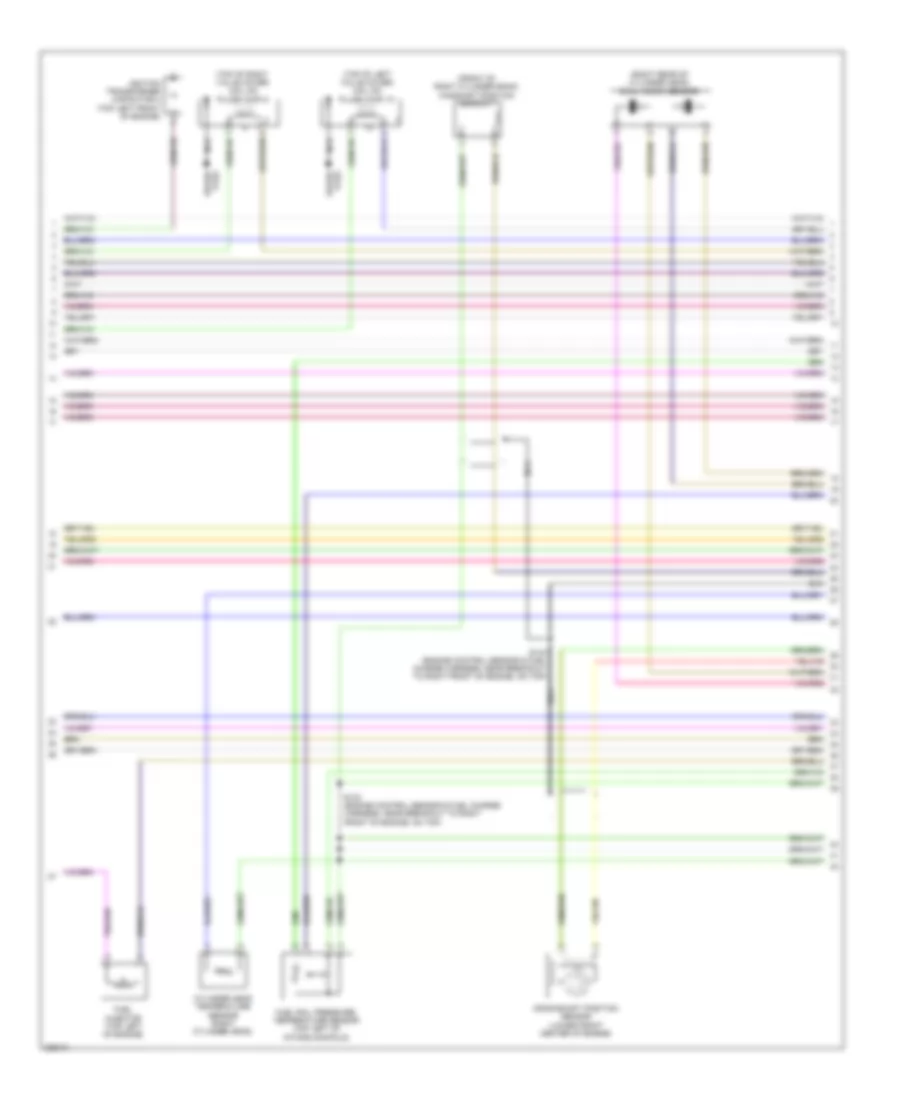
5.4L, Engine Performance Wiring Diagram (6 of 6) for Ford Cab & Chassis F350 Super Duty 2010
List of elements for 5.4L, Engine Performance Wiring Diagram (6 of 6) for Ford Cab & Chassis F350 Super Duty 2010:
- (engine control sensor & fuel charge harness, near breakout to rear left of engine, on back)
- (engine control sensor & fuel charge harness, near breakout to rear left of engine, on top)
- Accr
- Accs
- Assembly)
- Bps
- Brake pressure switch (bottom of master cylinder)
- C175e
- Cd 1a
- Cd 4g
- Cd 6e
- Cd 7c
- Cdc10
- Cdc15
- Ce132
- Ce205
- Ce206
- Ce207
- Ce208
- Ce209
- Ce210
- Ce211
- Ce212
- Ce235
- Ce236
- Ce303
- Ce304
- Ce305
- Ce306
- Ce307
- Ce308
- Ce309
- Ce310
- Ce412
- Ce421
- Ce422
- Ce426
- Ce608
- Ces09
- Ch302
- Ch421
- Cht
- Ckp+
- Ckp-
- Cmp 1
- Cmp 2
- Cop 2d
- Cop 3b
- Cop 5d
- Cop 8h
- De706
- Drain
- Electronic throttle control (etc) motor (throttle body
- Etcref
- Etcrtn
- Evap canister purge valve (right rear of engine compt)
- Evapcp
- Frp
- Frt
- G103 (right rear of engine compt)
- Genli
- Genrc
- Heated oxygen sensor (ho2s) 11 (right exhaust manifold)
- Heated oxygen sensor (ho2s) 21 (left exhaust manifold)
- Ho2s 11
- Ho2s 21
- Htr 11
- Htr 21
- Iat
- Inj 1
- Inj 2
- Inj 3
- Inj 4
- Inj 5
- Inj 6
- Inj 7
- Inj 8
- Injpwrm
- Ks 2+
- Ks 2-
- Ks1+
- Ks1-
- Le423
- Le428
- Maf
- Mafrtn
- Mass air flow/intake air temperature (maf/iat) sensor (left front of engine compt)
- Powertrain control module (pcm) (left side of firewall)
- Re135
- Re320
- Re323
- Re324
- Re405
- Re427
- S107
- S155
- S162
- Sigtne
- Solid state
- Starting/ charging system
- Tacm+
- Tacm-
- Throttle position sensor (tps) (throttle body assembly)
- Tps1 ns
- Tps2 ps
- Variable camshaft timing (vct) solenoid 2 (left front top of engine)
- Variable camshaft timing (vct) solenoid1 (right top front of engine)
- Vct 1
- Vct 2
- Ve706
- Ve707
- Ve711
- Ve712
- Ve727
- Ve728
- Ve735
- Ve737
- Ve740
- Ve801
- Ve802
- Ve807
- Ve818
- Ve819
- Vref-e
6.4L DIESEL
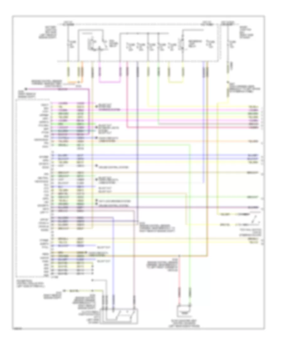
6.4L Diesel, Engine Performance Wiring Diagram (1 of 6) for Ford Cab & Chassis F350 Super Duty 2010
List of elements for 6.4L Diesel, Engine Performance Wiring Diagram (1 of 6) for Ford Cab & Chassis F350 Super Duty 2010:
- (right rear of engine compt) g103
- A/c clutch relay
- A/c clutch switch
- Accr
- Air conditioning system
- Anti-lock brakes system
- App 1
- App 2
- App 2 vref
- Battery junction box (bjb) (left rear of engine compt)
- Bcp il
- Bcp sw
- Bpp
- Bps
- C1232b
- Case gnd
- Cbb71
- Cbb76
- Cca10
- Cca15
- Ccb06
- Cdc12
- Cdc35
- Cdc38
- Cdc47
- Cdc48
- Ce140
- Ce237
- Ce326
- Ce904
- Ce911
- Ce912
- Ce913
- Ce914
- Ce925
- Ces09
- Cet21
- Ch302
- Clutch pedal position switch (m/t) (left side of dash)
- Cmc25
- Computer data lines system
- Cpp bt
- Cpp tt
- Crank
- Cruise control system
- Cto
- Dpf
- Egt 11
- Egt 12
- Egt 13
- Fpm
- Fuse 10a
- Fuse 20a
- Fuse 50a
- Fuse 5a
- G103 (right rear of engine compt)
- G106 (right rear of engine compt)
- Gd113
- Gd164
- Gencom
- Genmon
- Hot at all times
- Hot in run or start
- Hs can +
- Hs can -
- Isp-r
- Kapwr
- Le136
- Le137
- Le434
- Not used
- Pba
- Pcm power relay
- Pcmrc
- Powertrain control module (pcm) (left side of firewall)
- Pto
- Pto gnd
- Pto ind
- Pto rpm
- Pto vref
- Pwrgnd
- Re136
- Re137
- Re327
- Res08
- Reversing lamp relay
- S101
- S102
- S117
- S123
- S162
- S208 (main harness, near breakout to right side of hvac housing)
- Sbb36
- Sccs
- Sccs rtn
- Sigrtn
- Smc
- Smr/start
- Starting/charging system
- Tracs
- Tracsil
- Transmissions system
- Vdb04
- Vdb05
- Ve225
- Ve701
- Ve702
- Ve746
- Ve747
- Ve748
- Ve749
- Ve822
- Ve823
- Ves10
- Vmv05
- Vpwr
- Vref
- Vso
- Vss
- Wfs
6.4L Diesel, Engine Performance Wiring Diagram (2 of 6) for Ford Cab & Chassis F350 Super Duty 2010
List of elements for 6.4L Diesel, Engine Performance Wiring Diagram (2 of 6) for Ford Cab & Chassis F350 Super Duty 2010:
- (inside of left frame rail) water in fuel sensor
- (left side of dash) brake pedal position switch
- (left side of dash) park brake switch
- (main harness, behind right side of dash, right of radio opening)
- C2280a
- C2280b
- C2280c
- Computer data lines system
- Fuel pump module
- Fuel sender 1
- Fuel sender 2
- Fuel sender rtn 2
- Fuel tank select
- Fuel tank selector switch
- Fuel tank selector valve (left rear of cab)
- Fuel tank sensor
- Fuse 10a
- G203 (center of dash)
- G300 (super cab: left side of dash) (except super cab: left "a" pillar)
- Hot at all times
- Hot in run or acc
- Instrument cluster (ic)
- Micro
- Ms can +
- Ms can -
- Narrow frame
- Primary
- S106 (engine control sensor harness, near breakout to left front of frame)
- S116 (engine control sensor harness, near breakout to left front corner of vehicle)
- S235
- S2439
- S245
- S246 (main harness, behind right side of dash, right of radio opening)
- S304
- S326
- Secondary
- Secondary fuel tank sensor
- Sense
- Smart junction box (right side of dash)
- W/ dual fuel tank
- W/o dual fuel tank
- Wide frame
6.4L Diesel, Engine Performance Wiring Diagram (3 of 6) for Ford Cab & Chassis F350 Super Duty 2010
List of elements for 6.4L Diesel, Engine Performance Wiring Diagram (3 of 6) for Ford Cab & Chassis F350 Super Duty 2010:
- (engine control sensor harness, near breakout to right rear of engine compartment) s107
- (near left side of transmission) fuel pump
- (right kick panel) inertia fuel shutoff (ifs) switch
- Battery junction box (bjb) (left rear of engine compt)
- Brake pressure switch (bottom of master cylinder)
- C1273a
- C1273b
- Cbb12
- Ce243
- Ce244
- Ce245
- Ce246
- Ce247
- Ce248
- Ce251
- Ce252
- Ce513
- Ce514
- Cooling fans system
- Fuel cooler (left front of engine)
- Fuel pump diode
- Fuel pump relay
- Fuse 20a
- Fuse 50a
- Fuse 5a
- G104 (left rear of engine compt)
- Glow plug control module (gpcm) (top right front of engine)
- Gpc
- Gpd
- Hot at all times
- Kapwr
- Left glow plug bank (lower left of engine)
- Right glow plug bank (right side of engine)
- S1000
- S1009 (engine control sensor harness, near breakout to right front of engine, on top)
- S1010
- S103
- S113
- S124
- Sbb27
- Sbb47
- Vpwr
6.4L Diesel, Engine Performance Wiring Diagram (4 of 6) for Ford Cab & Chassis F350 Super Duty 2010
List of elements for 6.4L Diesel, Engine Performance Wiring Diagram (4 of 6) for Ford Cab & Chassis F350 Super Duty 2010:
- (accelerator pedal support) accelerator pedal position sensor
- (except
- (not used)
- (right exhaust)
- (right side frame rail)
- Acp sw
- Air conditioning system
- C1232e
- Ce250
- Ce315
- Ce514
- Cec11
- Ch425
- Ckp +
- Ckp -
- Cooling fans
- Crankshaft position sensor
- Diesel particulate filter pressure sensor
- Egrt1
- Egrvp
- Exhaust gas temperature sensor 1
- Exhaust gas temperature sensor 2
- Exhaust gas temperature sensor 3
- Fcc
- Fcv
- Fcv
- Fuel injector 2 (top left of engine)
- Fuel injector 3 (top right of engine)
- Fuel injector 5 (top right rear of engine)
- Fuel injector 8 (left rear of engine)
- Gpd
- High sulfur)
- Iat 2
- Imrc
- Inj 2 -
- Inj 3 -
- Inj 5 -
- Inj 8 -
- Powertrain control module (pcm) (left side of firewall)
- Re135
- Re206
- Re207
- Re209
- Re212
- Red
- S146
- S408 (tail lamps harness, near breakout to left middle of frame)
- Sig
- System
- Vbpwr
- Ve711
- Ve721
- Ve722
- Ve740
- Vec03
- Vec10
6.4L Diesel, Engine Performance Wiring Diagram (5 of 6) for Ford Cab & Chassis F350 Super Duty 2010
List of elements for 6.4L Diesel, Engine Performance Wiring Diagram (5 of 6) for Ford Cab & Chassis F350 Super Duty 2010:
- (engine control sensor harness, near breakout to front right side of engine, on top)
- (engine control sensor harness, near breakout to right front of engine, on top)
- (engine control sensor harness, near breakout to right rear of engine compt)
- (engine control sensor harness, near breakout to right rear of engine compt) s1007
- (except
- (intake tube assembly) intake air temperature 2 (iat2) sensor
- (right side of engine) manifold absolute pressure (map) sensor
- (top front of engine)
- C1906a
- C1906b
- Computer data lines system
- Egr temperature sensor 1 (top front of engine)
- Egr throttle plate valve (front of engine, on top)
- Egr valve actuator
- Engine oil temperature (eot) sensor (top right of engine)
- G103 (right rear of engine compt)
- High pressure fuel pump (rear of intake manifold)
- High sulfur)
- Pressure
- Red
- S1002 (engine control sensor harness, near breakout to right rear of engine compt)
- S1005
- S1006 (engine control sensor harness, near breakout to right rear of engine compt)
- S1013
- S114
- Turbo charger actuator (top left side of engine)
- Volume
6.4L Diesel, Engine Performance Wiring Diagram (6 of 6) for Ford Cab & Chassis F350 Super Duty 2010
List of elements for 6.4L Diesel, Engine Performance Wiring Diagram (6 of 6) for Ford Cab & Chassis F350 Super Duty 2010:
- (engine control sensor harness, near breakout to right front of engine, on top) s1012
- (engine control sensor harness, near breakout to right rear of engine compt)
- (lower left front of engine) camshaft position sensor
- (top left rear of engine) fuel injector 6
- (top left side of engine) fuel injector 4
- (top right rear of engine) fuel injector 7
- (top right side of engine) fuel injector 1
- Accs
- Air conditioning system
- C1232e
- Cdc10
- Cdc15
- Ce205
- Ce206
- Ce207
- Ce208
- Ce209
- Ce210
- Ce211
- Ce212
- Ce316
- Ce321
- Ce328
- Ch421
- Cmp +
- Cmp -
- Cooling fans system
- De135
- Ect
- Egr temperature sensor 2 (except high sulfur) (top front of engine)
- Egrt2
- Engine coolant temperature (ect) sensor (front of engine)
- Eot
- Exhaust pressure (ep) sensor (left rear of engine)
- Fpcv
- Frp
- Frt
- Fuel rail pressure sensor (top right of right valve cover)
- Fuel rail temperature sensor (top right of right valve cover)
- Fvcv
- Gd119
- Ge513
- Gencom
- Genmon
- Gnd
- Gpc
- Iat 1
- Imtv
- Inj 1 +
- Inj 1 -
- Inj 2 +
- Inj 3 +
- Inj 4 +
- Inj 4 -
- Inj 5 +
- Inj 6 +
- Inj 6 -
- Inj 7 +
- Inj 7 -
- Inj 8 +
- Le139
- Le423
- Lr139
- Maf
- Maf rtn
- Map
- Mass air flow (maf) sensor (at air intake tube)
- Powertrain control module (pcm) (left side of firewall)
- Re139
- Re205
- Re208
- Re210
- Re211
- Re230
- Re405
- Re406
- Re429
- Red
- Ref
- Rtn
- S1001
- Shldrtn
- Sig
- Sig rtn
- Sigrtn
- Starting/ charging system
- Ve607
- Ve706
- Ve716
- Ve717
- Ve726
- Ve727
- Ve728
- Ve740
- Ve803
- Ve921
- Vref
6.8L
6.8L, Engine Performance Wiring Diagram (1 of 6) for Ford Cab & Chassis F350 Super Duty 2010
List of elements for 6.8L, Engine Performance Wiring Diagram (1 of 6) for Ford Cab & Chassis F350 Super Duty 2010:
- (engine control sensor harness, near battery junction box)
- (engine control sensor harness, near breakout to right rear of engine compt)
- (left side of dash)
- Anti-lock brakes system
- App1
- App2
- App3
- Appref
- Apprtn
- Battery junction box (bjb) (left rear of engine compt)
- Bpp
- C175b
- C2280b
- Canv
- Cat15
- Cbb71
- Cbb76
- Ccb08
- Cdb08
- Cdc12
- Ce114
- Ce237
- Ce326
- Ce903
- Ce904
- Ce912
- Ce913
- Ce914
- Ce924
- Cet21
- Cls05
- Cls28
- Clutch pedal position switch (m/t)
- Computer data lines system
- Cpp bt
- Cpp tt
- Cruise control system
- Cto
- Etcref
- Etcrtn
- Evap canister vent control solenoid (left rear side of frame)
- Fpc
- Fpm
- Ftpref
- Ftpt
- Fuse 10a
- Fuse 15a
- Fuse 20a
- Fuse 30a
- Fuse 5a
- G103 (right rear of engine compt)
- G106 (right rear of engine compt)
- Gd113
- Gd164
- Gnd
- Hot at all times
- Hot in run or start
- Hscan bus+
- Hscan bus-
- Isp r
- Kapwr
- Le136
- Le137
- Le230
- Nca
- Neutral
- Of steering wheel)
- Park
- Pcm power relay
- Pcmrc
- Peps
- Powertrain control module (pcm) (left side of firewall)
- Pto
- Pto rpm
- Ptoil
- Ptoir
- Re136
- Re137
- Re407
- Res08
- Reversing lamp relay
- Rlc
- S102 (engine control sensor harness, near breakout to right rear of engine compt)
- S154
- S158 (engine control sensor harness, near breakout to left front corner of vehicle)
- S162
- Sbb36
- Sccs
- Sccsrtn
- Sigrtn
- Smart junction box (right side of dash)
- Smc
- Tcs
- Tow haul switch (top of steering column)
- Vdb04
- Vdb05
- Ve225
- Ve518
- Ve701
- Ve702
- Ve703
- Ve745
- Ve822
- Ve922
- Ves10
- Vmc05
- Vpwr1-a
- Vpwr1-b
- Vsc
- Vsout
6.8L, Engine Performance Wiring Diagram (2 of 6) for Ford Cab & Chassis F350 Super Duty 2010
List of elements for 6.8L, Engine Performance Wiring Diagram (2 of 6) for Ford Cab & Chassis F350 Super Duty 2010:
- (accelerator pedal support) accelerator pedal position sensor
- (engine control sensor harness, near battery junction box) s156
- (engine control sensor harness, near breakout to left front of frame)
- (left rear of engine compt)
- (tail lamps harness, in breakout to left rear of frame)
- A/c clutch relay
- A/c compressor clutch field coil (a/c compressor)
- A/c compressor cycling switch (right rear of engine compt)
- A/c high pressure switch (right side of engine compt)
- Battery junction box (bjb) (left rear of engine compt)
- Ce515
- Ce911
- Computer data lines system
- Fpc
- Fpm
- Fppwr
- Fprtn
- Fuel pump diode
- Fuel pump driver module (left rear frame rail)
- Fuel pump module
- Fuel pump relay
- Fuel sender 1
- Fuel sender rtn 1
- Fuel tank pressure (ftp) sensor (above left side of rear axle)
- Fuse 20a
- Fuse 5a
- G108
- G108 (left rear of engine compt)
- G400 (left rear of frame)
- Gd117
- Hot at all times
- Hot in run or start
- Hs can +
- Hs can -
- Inertia fuel shutoff (ifs) switch (right kick panel)
- Instrument cluster (ic)
- Le230
- Narrow frame
- Nca
- Pwrgrd
- Re407
- Re515
- Rmc32
- S101
- S115
- S120
- S123
- S128 (engine control sensor harness, in breakout to master cylinder)
- S401
- Ve225
- Ve518
- Ve922
- Vmc11
- Vpwr
- Wide frame
6.8L, Engine Performance Wiring Diagram (3 of 6) for Ford Cab & Chassis F350 Super Duty 2010
List of elements for 6.8L, Engine Performance Wiring Diagram (3 of 6) for Ford Cab & Chassis F350 Super Duty 2010:
- (backup lamp switch to rear lamp feed harness, near breakout to front left of transmission, near top) s194
- (left rear of engine compt) battery junction box (bjb)
- (left rear of engine compt) g108
- A/c clutch diode
- Anti-lock brakes system
- C175t
- Cca10
- Cca15
- Cdc35
- Cdc38
- Ce233
- Ce234
- Cet05
- Cet06
- Cet07
- Cet08
- Cet09
- Cet22
- Cet25
- Cet49
- Cet50
- Crank
- Heated oxygen sensor (ho2s) 22 (wide frame) (left side of transmission)
- Ho2s 12
- Ho2s 22
- Htr 12
- Htr 22
- Ignition transformer capacitor 1 (top right front of engine)
- Iss
- Le111
- Lpc
- Oss
- Output shaft speed (oss) sensor (top of transmission extension housing)
- Pc-a
- Powertrain control module (pcm) (left side of firewall)
- Re406
- Ret04
- Ret24
- S115
- S196
- Sig rtn
- Sigrtnt
- Smr/start
- Speed sensor assembly (top left side of transmission)
- Sspc a
- Sspc b
- Sspc c
- Sspc d
- Sspc e
- Sspc-a
- Sspc-b
- Sspc-c
- Sspc-d
- Sspc-e
- Starting/ charging system
- Tcc
- Tft
- Torqshift transmission
- Tr p
- Tr-p
- Tracs
- Tracsil
- Tspc
- Tss
- Vbpwr
- Ve730
- Ve733
- Ve744
- Vet27
- Vet33
6.8L, Engine Performance Wiring Diagram (4 of 6) for Ford Cab & Chassis F350 Super Duty 2010
List of elements for 6.8L, Engine Performance Wiring Diagram (4 of 6) for Ford Cab & Chassis F350 Super Duty 2010:
- (backup lamp switch to rear lamp feed harness, near breakout to front left of transmission, near top) s183
- (engine control sensor & fuel charge harness, near breakout to front left side of engine, on top)
- (engine control sensor & fuel charge harness, near breakout to rear left side of engine, on top) s136
- (rear of catalytic converter)
- (top of left valve cover) coil on plugs (cop) 6, 7, 8 & 9
- (top of right valve cover) coil on plugs (cop) 1, 2, 3 & 4
- Fuel injectors 1,2,3,4 & 5 (1,2 & 5: top right of engine) (3 & 4: top right rear of engine)
- Fuel injectors 6,7,8 & 10 (6, 7 & 10: top left of engine) (8: top left rear of engine)
- Heated oxygen sensor (ho2s) 12 (wide frame)
- Nca
- Plug spark
- S127 (engine control sensor & fuel charge harness, near rear right side of engine, on top)
- S132 (engine control sensor & fuel charge harness, near breakout to right front side of engine, on top)
- S135
- S181
- Spark plug
6.8L, Engine Performance Wiring Diagram (5 of 6) for Ford Cab & Chassis F350 Super Duty 2010
List of elements for 6.8L, Engine Performance Wiring Diagram (5 of 6) for Ford Cab & Chassis F350 Super Duty 2010:
- (front of right cylinder bank) camshaft position sensor 1
- (right rear of cylinder head) dual knock sensor
- (top of left valve cover) coil on plugs (cop) 10
- (top of right valve cover) coil on plugs (cop) 5
- Crankshaft position sensor (lower front center of engine)
- Cylinder head temperature sensor (right cylinder head)
- Fuel injector (top left of engine)
- Fuel rail pressure/ temperature sensor (top left of intake manifold)
- Ignition transformer capacitor 2 (top left front of engine)
- Nca
- S133 (engine control sensor & fuel charge harness, near breakout to right front of engine, on top)
- S134 (engine control sensor & fuel charge harness, near breakout to right front of engine, on top)
- Spark plug
6.8L, Engine Performance Wiring Diagram (6 of 6) for Ford Cab & Chassis F350 Super Duty 2010
List of elements for 6.8L, Engine Performance Wiring Diagram (6 of 6) for Ford Cab & Chassis F350 Super Duty 2010:
- (engine control sensor & fuel charge harness, near breakout to rear left of engine, on back)
- (engine control sensor & fuel charge harness, near breakout to rear left of engine, on top)
- Accr
- Accs
- Bps
- Brake pressure switch (bottom of master cylinder)
- C175e
- Cdc10
- Cdc15
- Ce132
- Ce205
- Ce206
- Ce207
- Ce208
- Ce209
- Ce210
- Ce211
- Ce212
- Ce213
- Ce214
- Ce235
- Ce236
- Ce303
- Ce304
- Ce305
- Ce306
- Ce307
- Ce308
- Ce309
- Ce310
- Ce311
- Ce312
- Ce316
- Ce412
- Ce426
- Ce608
- Ces09
- Ch302
- Ch421
- Cht
- Ckpn
- Ckpp
- Cmp 1
- Cop10d
- Cop1a
- Cop2e
- Cop3g
- Cop4i
- Cop5d
- Cop6b
- Cop7f
- Cop8h
- Cop9j
- De706
- Drain
- Electronic throttle control (etc) motor (throttle body
- Etcref1
- Etcrtn
- Evap canister purge valve (right rear of engine compt)
- Evapcp
- Frp
- Frt
- G103 (right rear of engine compt)
- Genli
- Genrc
- Gnd
- Heated oxygen sensor (ho2s) 11 (right exhaust manifold)
- Heated oxygen sensor (ho2s) 21 (left exhaust manifold)
- Ho2s 11
- Ho2s 21
- Htr 11
- Htr 21
- Iat
- Imtv
- Inj 1
- Inj 10
- Inj 2
- Inj 3
- Inj 4
- Inj 5
- Inj 6
- Inj 7
- Inj 8
- Inj 9
- Injpwrm
- Intake manifold tuning valve (imtv) (top right of engine)
- Ks 1+
- Ks 1-
- Ks2+
- Ks2-
- Le423
- Le428
- Maf
- Mafrtn
- Mass air flow (maf) sensor (left front of engine compt)
- Powertrain control module (pcm) (left side of firewall)
- Re135
- Re320
- Re323
- Re324
- Re405
- Re427
- S107
- S114
- S155
- Sigtne
- Solid state
- Starting/ charging system
- Tacm n
- Tacm+
- Throttle position sensor (tps) (top center of engine)
- Tps1 ns
- Tps2 ps
- Ve706
- Ve711
- Ve712
- Ve727
- Ve728
- Ve735
- Ve737
- Ve740
- Ve801
- Ve802
- Ve807
- Ve818
- Ve819
- Vpwr
- Vref-e