ENGINE PERFORMANCE
4.9L
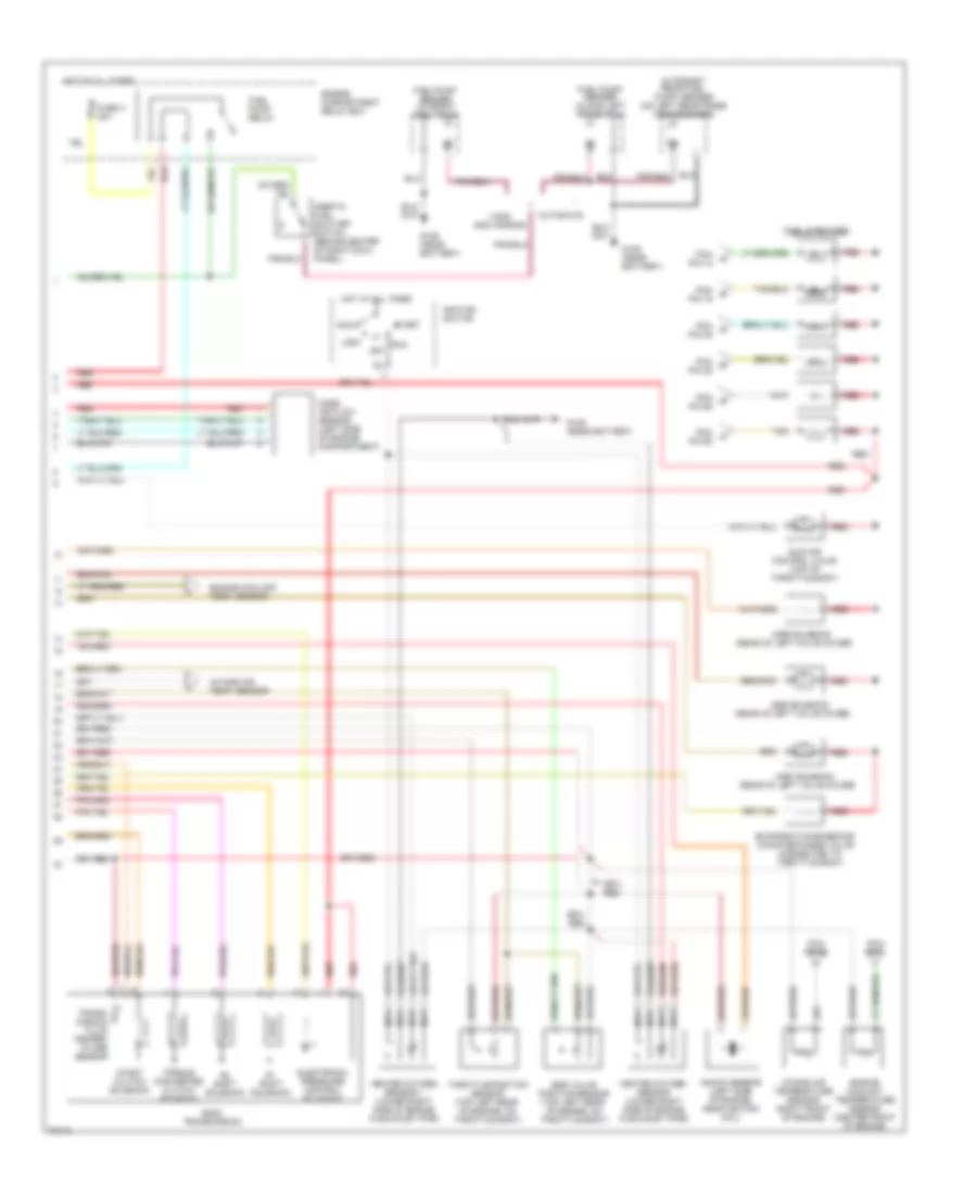
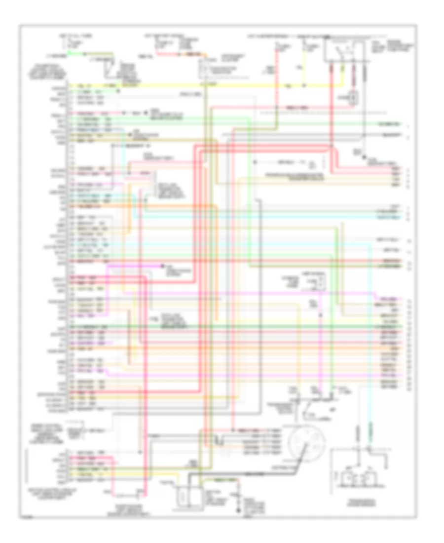
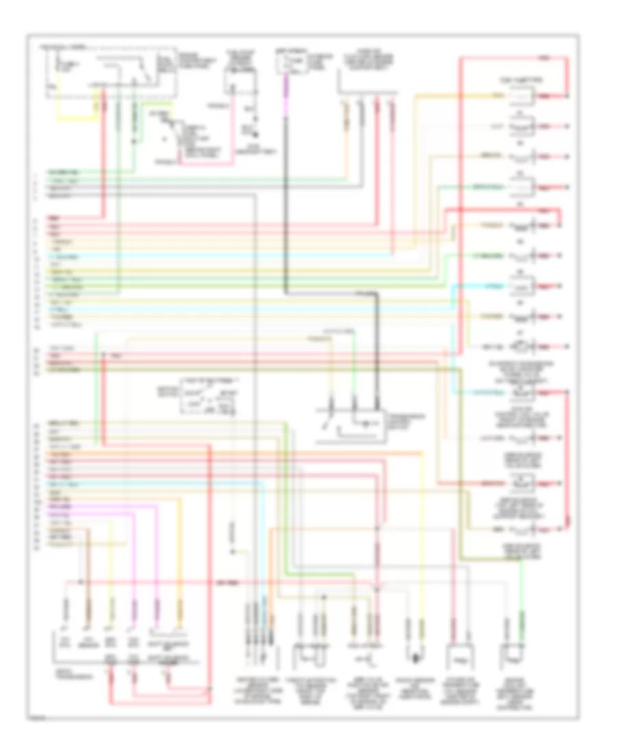
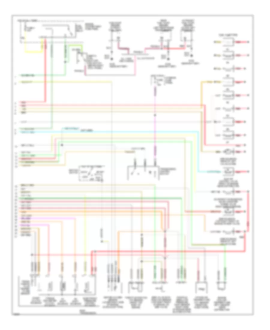
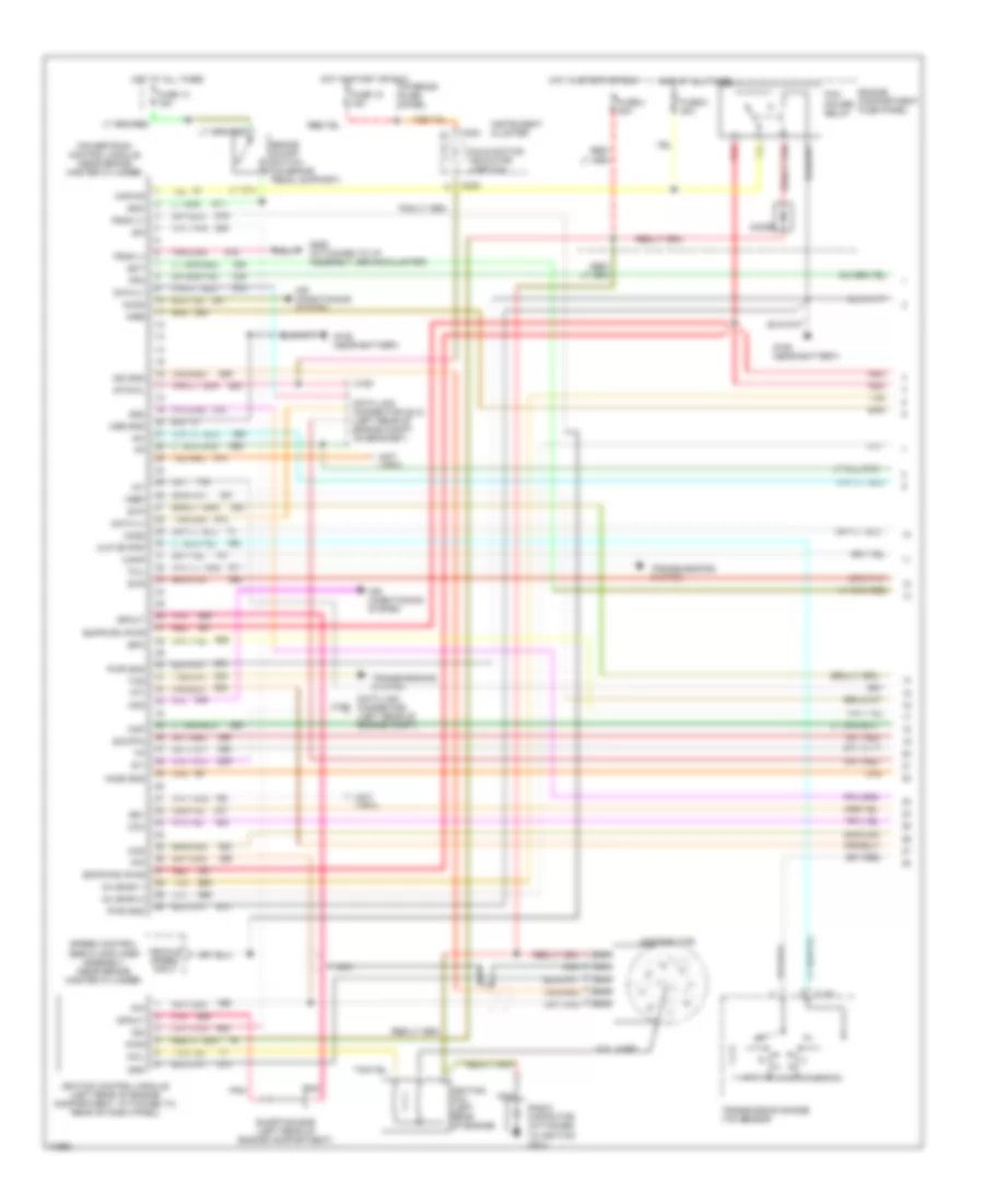
4.9L, Engine Performance Wiring Diagrams, California (1 of 2) for Ford Club Wagon E150 1995

List of elements for 4.9L, Engine Performance Wiring Diagrams, California (1 of 2) for Ford Club Wagon E150 1995:
- A/c system
- Accs
- Air conditioning (a/c) system
- Airb
- Aird
- Boo
- Brake on/off switch (top left side of brake/clutch pedal support)
- C162
- C163
- C233
- Ccs
- Ckp
- Coil
- Coil wire
- Cse gnd
- Data link connector
- Data link connector (left front corner of engine compt)
- Diode
- Distributor
- Ect
- Engine compartment fuse box
- Epc
- Epcpwr/vpwr
- Evap
- Evp
- Evr
- Fpm
- Fuel inj 1
- Fuel inj 2
- Fuel inj 3
- Fuel inj 4
- Fuel inj 5
- Fuel inj 6
- Fuel injector 5
- Fuel injector 6
- Fuel injs. 2 & 1
- Fuse 1 15a
- Fuse 18 15a
- Fuse i 20a
- Fuse panel
- Fuse u 30a
- G104 (rear of left fender apron)
- G106 (near battery)
- G206 (attached to i/p, behind cluster)
- Gnd
- H02s (1)
- Ho2s (2)
- Hot at all times
- Hot in start or run
- Iac
- Iat
- Idm
- Ign gnd
- Ignition coil (left front of engine)
- Ignition control module (left rear of engine compartment on fender apron)
- Instrument cluster
- Kapwr
- Maf
- Malfunction indicator
- Nca
- Pcm pin 32
- Pcm pin 41
- Pcm power relay
- Pip
- Pnk
- Powertrain control module (left side of safety wall)
- Programmable speedometer/ odometer module
- Pwr
- Pwr gnd
- Radio capacitor (near ignition coil)
- Red
- Shorting bar (near ignition control module)
- Sig rtn
- Spout
- Ss1
- Ss2
- Starting system
- Sto/mil
- Tan
- Tcc
- Tcil
- Tcs
- Tft
- Tr or pnp
- Transmission control switch
- Transmission range sensor
- Transmission switch
- Vehicle speed output
- Vip data link
- Vip data link (+)
- Vip data link (-)
- Vpwr
- Vref
- Vss (+)
- Vss (-)
- W/ c6
- W/ e4od
- Wac relay
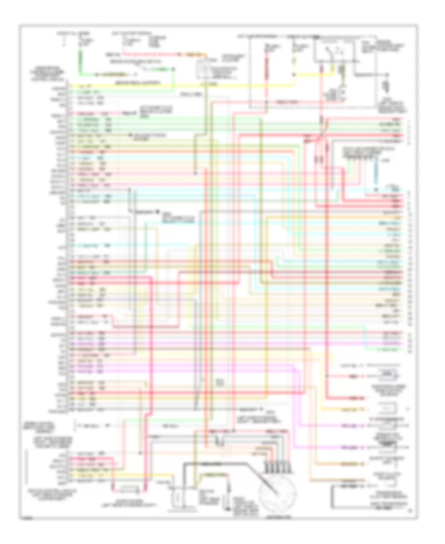
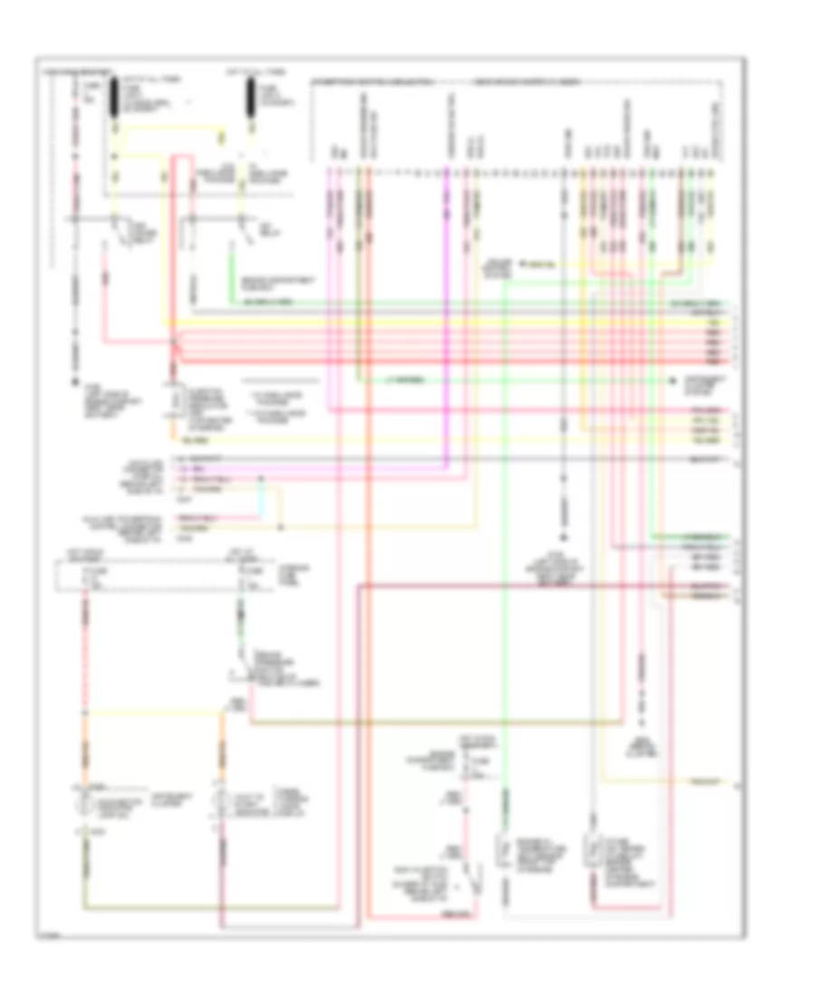
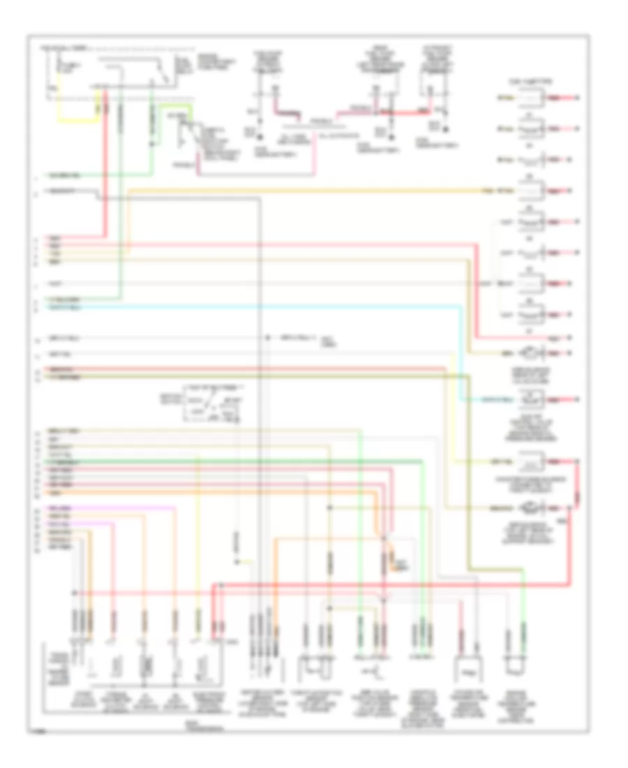
4.9L, Engine Performance Wiring Diagrams, California (2 of 2) for Ford Club Wagon E150 1995
List of elements for 4.9L, Engine Performance Wiring Diagrams, California (2 of 2) for Ford Club Wagon E150 1995:
- #1 shift solenoid
- #2 shift solenoid
- (connected to throttle body)
- (rear of left valve cover)
- Acc
- Airb solenoid
- Aird solenoid
- Coast clutch solenoid
- Cutaways
- E40d transmission
- Egr solenoid
- Egr valve position sensor (top left rear of engine, on throttle body)
- Electronic pressure control solenoid
- Engine compartment relay box
- Engine coolant temp. sensor
- Engine coolant temperature sensor (center front of engine)
- Evaporative emissions canister purge valve
- Fuel injectors
- Fuel pump relay
- Fuel pump/ sender (along left frame rail)
- Fuel/pump sender (in front fuel tank)
- Fuse h 30a
- G106 (near battery)
- Heated oxygen sensor (lower right side of engine in exhaust pipe)
- Heated oxygen sensor 1 (lower right side of engine in exhaust pipe)
- Hot at all times
- Idle air control valve (top of throttle body)
- Ignition switch
- In-transit rear fuel pump/ sender (on left rear frame crossmember)
- Inertia fuel shut-off switch (behind center of right cowl panel)
- Intake air temp. sensor
- Intake air temperature sensor (right front of engine)
- Knock sensor (left side of engine, near ignition coil)
- Lock
- Mass air flow sensor (left side of engine compartment)
- Nca
- Off
- Pcm a
- Pcm b
- Pcm d
- Pcm e
- Pcm g
- Pcm h
- Pcm pin 25
- Pcm pin 7
- Pin 12
- Pin 15
- Pin 35
- Pin 39
- Pin 58
- Pin 59
- Red
- Run
- Start
- Tan
- Throttle position sensor (top left rear of engine, on throttle body)
- Torque converter clutch solenoid
- Trans- mission fluid temper- ature sensor
- Vans and wagons
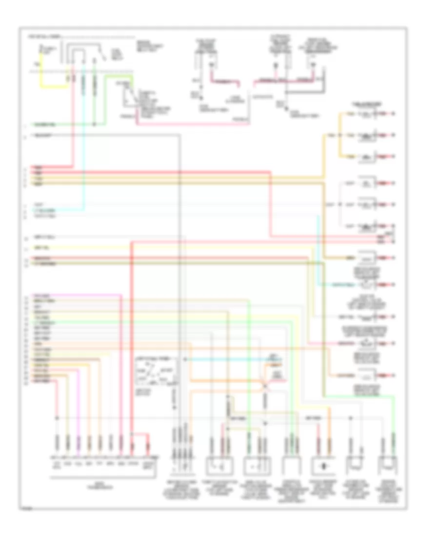
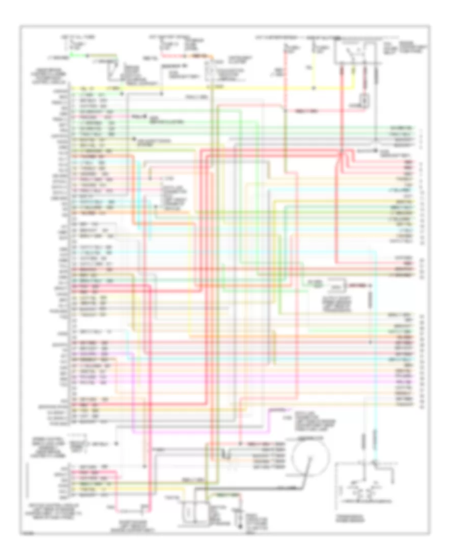
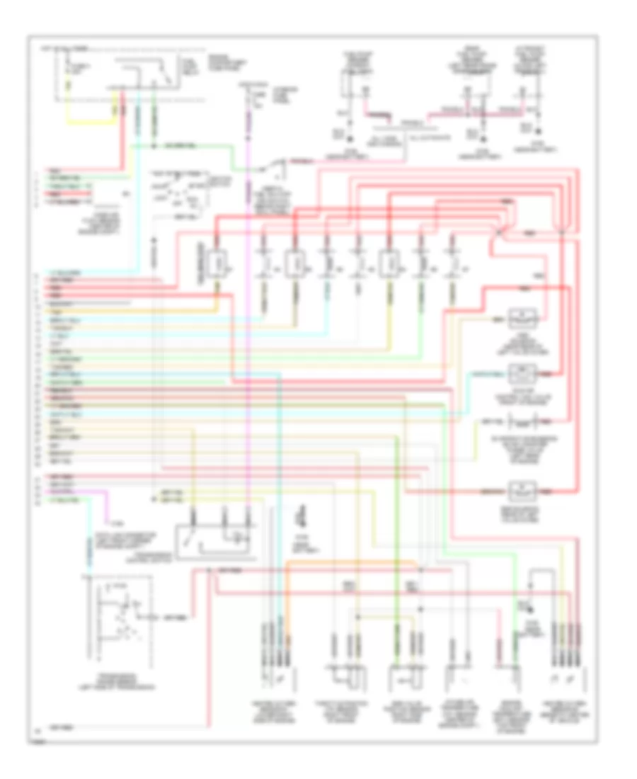
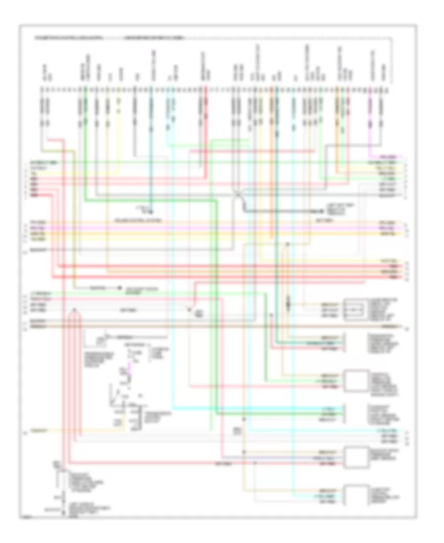
4.9L, Engine Performance Wiring Diagrams, Except California (1 of 2) for Ford Club Wagon E150 1995
List of elements for 4.9L, Engine Performance Wiring Diagrams, Except California (1 of 2) for Ford Club Wagon E150 1995:
- Accs
- Acd
- Air conditioning system
- Airb
- Aird
- Boo
- Brake on/off switch (behind steering column)
- C162
- C163
- C233
- Ccs
- Coil
- Coil wire
- Cse gnd
- Data (+)
- Data (-)
- Data link connector (left side of engine compt)
- Diode
- Distributor
- Ect
- Engine compartment fuse panel
- Epc
- Epcpwr/vpwr
- Evap
- Evp
- Evr
- Fpm
- Fuse 1 15a
- Fuse 15a
- Fuse 18 15a
- Fuse c 30a
- Fuse u 30a
- G106 (near battery)
- G206 (attached to i/p, behind cluster)
- Gnd
- Ho2s
- Ho2s gnd
- Hot at all times
- Hot in run
- Hot in start or run
- Iac
- Iat
- Idm
- Ign gnd
- Ignition coil (left front of engine)
- Ignition control module (left rear of engine compartment)
- Inj bank 1
- Inj bank 2
- Instrument cluster
- Interior fuse panel
- Kapwr
- Malfunction indicator
- Map
- Mlp or pnp
- Nca
- Pcm power relay
- Pip
- Pnk
- Powertrain control module (left side of brake master cylinder)
- Programmable speedometer/ odometer module
- Psom (+)
- Psom (-)
- Pwr
- Pwr gnd
- Radio capacitor (attached to ignition coil)
- Red
- Shorting bar (left rear of engine compartment)
- Sig rtn
- Speed control/ servo amplifier assembly (near brake master cylinder)
- Spout
- Ss1
- Ss2
- Sti
- Sto/mil
- Tan
- Tcc
- Tcil
- Tcs
- Tft
- Transmission control switch
- Transmission range sensor
- Vehicle speed input
- Vpwr
- Vref
- Vs out
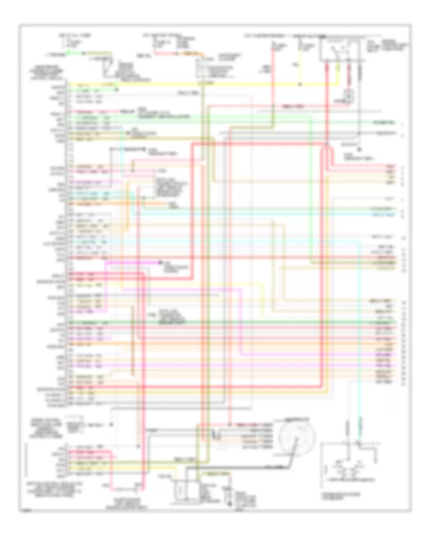
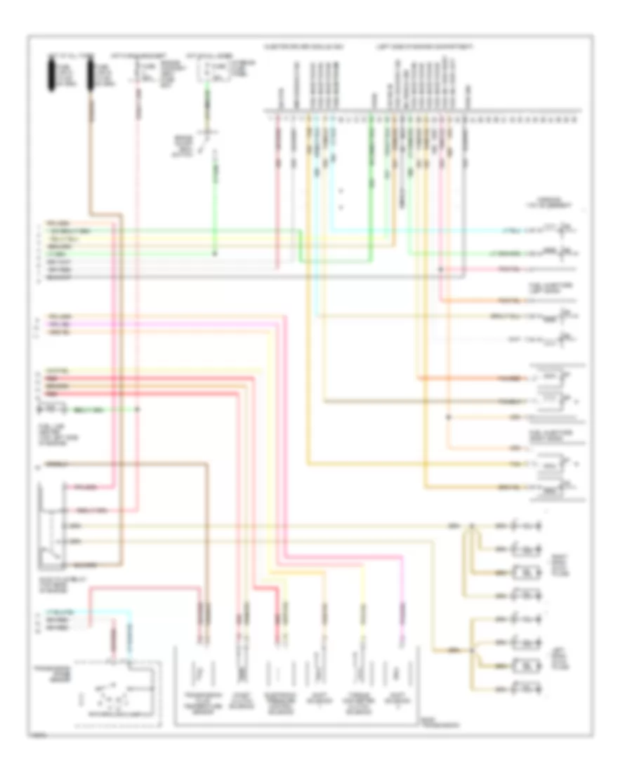
4.9L, Engine Performance Wiring Diagrams, Except California (2 of 2) for Ford Club Wagon E150 1995
List of elements for 4.9L, Engine Performance Wiring Diagrams, Except California (2 of 2) for Ford Club Wagon E150 1995:
- (not used)
- Acc
- Airb solenoid (rear of left valve cover)
- Aird solenoid (rear of left valve cover)
- C303
- Ccs
- Cutaways
- E40d transmission
- Egr solenoid (rear of left valve cover)
- Egr valve position sensor (top of egr valve, near throttle body)
- Engine compartment relay box
- Engine coolant temperature sensor (top front of engine)
- Epc
- Evaporative emissions canister purge valve (left rear of engine)
- Fuel injectors
- Fuel pump relay
- Fuel/pump sender (in front fuel tank)
- Fuse h 30a
- G106 (near battery)
- Heated oxygen sensor (lower right side of engine, mounted to exhaust pipe)
- Hot at all times
- Idle air control valve (left side of engine, on throttle body)
- Ignition switch
- In-transit fuel pump/ sender (along left frame rail)
- Inertia fuel shut-off switch (behind center of right cowl panel)
- Intake air temperature sensor (top left side of engine)
- Knock sensor (left side of engine, near ignition coil)
- Lock
- Manifold absolute pressure sensor (right side of engine compartment)
- Nca
- Off
- Rear fuel pump/ sender (on left rear frame crossmember)
- Red
- Run
- Ss1
- Ss2
- Start
- Tan
- Tcc
- Tft
- Tft rtn
- Throttle position sensor (top left side of engine)
- Vans & wagons
- Vpwr
- Vpwr (epc)
5.0L
5.0L, Engine Performance Wiring Diagrams (1 of 2) for Ford Club Wagon E150 1995
List of elements for 5.0L, Engine Performance Wiring Diagrams (1 of 2) for Ford Club Wagon E150 1995:
- (near brake master cylinder) powertrain control module
- Accs
- Air conditioning system
- Airb
- Aird
- Boo
- Brake on/off switch (on brake pedal support)
- C162
- C163
- C233
- Coil
- Coil wire
- Cse gnd
- Data (+)
- Data (-)
- Data link connector (dlc) (left front corner of vehicle)
- Data link connector (left side of engine compartment near park/turn lamp)
- Diode
- Distributor
- Ect
- Engine compartment fuse panel
- Epc
- Epcpwr/vpwr
- Evp
- Evr
- Fpm
- Fuse 1 15a
- Fuse 18 15a
- Fuse c 30a
- Fuse u 30a
- G106 (near battery)
- G206 (behind cluster)
- Gnd
- Ho2s
- Hot at all times
- Hot in start or run
- Iac
- Iat
- Idm
- Ign gnd
- Ignition coil (left rear of engine)
- Ignition control module (left rear of engine compartment, attached to rear of dash panel)
- Inj 3
- Inj 4
- Inj 5
- Inj 6
- Inj 7
- Inj 8
- Inj bank 1
- Inj bank 2
- Instrument cluster
- Interior fuse panel
- Kapwr
- Maf
- Maf rtn
- Malfunction indicator lamp (mil)
- Mlp
- Nca
- Oss
- Output shaft speed sensor (left rear of transmission)
- Pcm power relay
- Pip
- Pnk
- Psom (+)
- Psom (-)
- Pwr
- Pwr gnd
- Radio capacitor (attached to ignition coil)
- Red
- Shorting bar (left rear of engine compartment)
- Sig rtn
- Speed control servo amplifier assembly (near brake master cylinder)
- Spout
- Ss1
- Ss2
- Sti
- Sto/mil
- Tan
- Tan/red
- Tcc
- Tcil
- Tcs
- Tft
- Transmission range sensor
- Vehicle speed input
- Vpwr
- Vref
5.0L, Engine Performance Wiring Diagrams (2 of 2) for Ford Club Wagon E150 1995
List of elements for 5.0L, Engine Performance Wiring Diagrams (2 of 2) for Ford Club Wagon E150 1995:
- (near battery)
- 4r70w transmission
- Acc
- Airb solenoid (rear of left valve cover)
- Aird solenoid (rear of left valve cover)
- Egr solenoid (top left rear of engine on coil support bracket)
- Egr valve position (evap) sensor (top right front of engine, on egr valve)
- Engine compartment fuse panel
- Engine coolant temperature (ect) sensor (near distributor)
- Epc pwr
- Epc rtn
- Evaporative emissions (evap) canister purge valve (on throttle body)
- Fuel injectors
- Fuel pump relay
- Fuel/pump sender (in front fuel tank)
- Fuse 15a
- Fuse h 30a
- G106
- Heated oxygen sensor (lower right side of engine, on exhaust pipe)
- Hot at all times
- Hot in run
- Idle air control (iac) valve (front of engine near distributor)
- Ignition switch
- Inertia fuel shut-off (ifs) (behind right cowl panel)
- Intake air temperature (iat) sensor (center of engine compt)
- Interior fuse panel
- Knock sensor (ks) (near fuel injector #4)
- Lock
- Mass air flow (maf) sensor (center of engine compartment)
- Nca
- Off
- Red
- Run
- Shift solenoid power
- Shift solenoid ret
- Start
- Tan
- Tan/red
- Tcc pwr
- Tcc rtn
- Tft rtn
- Tft sensor
- Throttle position (tp) sensor (front top right of engine)
- Transmission control switch
5.8L
5.8L, Engine Performance Wiring Diagrams, California (1 of 2) for Ford Club Wagon E150 1995
List of elements for 5.8L, Engine Performance Wiring Diagrams, California (1 of 2) for Ford Club Wagon E150 1995:
- #1 shift solenoid
- #2 shift solenoid
- (attached to i/p, behind cluster) g206
- (brake pedal support)
- (left side of engine compt., near battery)
- (left side of engine compt., near brake master cylinder)
- (near brake master cylinder) powertrain control module
- Accs
- Air conditioning system
- Aird
- Boo
- Brake on/off (boo) switch
- C163
- C233
- Canp
- Ccs
- Coast clutch solenoid
- Coil
- Coil wire
- Cse gnd
- Data (+)
- Data (-)
- Data link connector (dlc) (left front corner of engine compt.)
- Distributor
- E40d transmission
- Ect
- Electronic pres- sure control solenoid
- Engine compartment fuse panel
- Epc
- Evp
- Evr
- Fpm
- Fuse 1 15a
- Fuse 18 15a
- Fuse c 30a
- Fuse u 30a
- G106
- G206 (attached to i/p, behind cluster)
- Gnd
- Ho2s (l)
- Ho2s (r)
- Hot at all times
- Hot in start or run
- Iac
- Iat
- Idm
- Idm (fto)
- Ign gnd
- Ignition coil (left rear of engine)
- Ignition control module (left rear of engine compartment)
- Inj 1
- Inj 2
- Inj 3
- Inj 4
- Inj 5
- Inj 6
- Inj 7
- Inj 8
- Instrument cluster
- Interior fuse panel
- Kapwr
- Maf
- Maf rtn
- Malfunction indicator lamp (mil)
- Mlp
- Nca
- Pcm power diode
- Pcm power relay
- Pip
- Pnk
- Psom (+)
- Psom (-)
- Pwr
- Pwr gnd
- Radio capacitor (left side of engine, near ignition coil)
- Red
- Shorting bar (left rear of engine compt.)
- Sig rtn
- Speed control servo/amplifier assembly
- Spout
- Ss1
- Ss2
- Sti
- Sto/mil
- Tan
- Tan/red
- Tcc
- Tcil
- Tcs
- Tfi
- Torque con- verter clutch solenoid
- Transmission fluid temp sensor
- Vpwr
- Vref
5.8L, Engine Performance Wiring Diagrams, California (2 of 2) for Ford Club Wagon E150 1995
List of elements for 5.8L, Engine Performance Wiring Diagrams, California (2 of 2) for Ford Club Wagon E150 1995:
- (near battery)
- Acc
- Aird solenoid (near rear of left valve cover)
- All cutaways
- All vans and wagons
- C162
- Data link connector (left front corner of engine compt.)
- Egr solenoid (rear of left valve cover)
- Egr valve position sensor (right side of engine)
- Engine compartment fuse panel
- Engine coolant temperature (ect) sensor (top front of engine)
- Evaporative emissions (evap) canister purge valve (left rear of engine)
- Fuel injectors
- Fuel pump relay
- Fuel/pump sender (in front fuel tank)
- Fuse 15a
- Fuse h 30a
- G106
- G106 (near battery)
- Heated oxygen sensor #1 (lower right side of engine)
- Heated oxygen sensor #2 (beneath center of vehicle)
- Hot at all times
- Hot in run
- Idle air control (iac) valve (front of engine)
- Ignition switch
- In-transit fuel pump/ sender (along left frame rail)
- Inertia fuel shutoff (ifs) switch (behind right cowl panel)
- Intake air temperature (iat) sensor (center of engine compt.)
- Interior fuse panel
- Lock
- Mass air flow sensor (center of engine compt.)
- Nca
- Off
- Rear fuel pump/ sender (left rear frame crossmember)
- Red
- Run
- Start
- Tan
- Tan/red
- Tcil
- Throttle position (tp) sensor (right front of engine)
- Transmission control switch
- Transmission range sensor (left side of transmission)
5.8L, Engine Performance Wiring Diagrams, Except California (1 of 2) for Ford Club Wagon E150 1995
List of elements for 5.8L, Engine Performance Wiring Diagrams, Except California (1 of 2) for Ford Club Wagon E150 1995:
- (near brake master cylinder) powertrain control module
- (not used)
- Accs
- Acd
- Air conditioning system
- Airb
- Aird
- Boo
- Brake on/off switch (on brake pedal support)
- C162
- C163
- C233
- Canp
- Ccc
- Ccs
- Coil
- Coil wire
- Cse gnd
- Data (+)
- Data (-)
- Data link connector (dlc) (left rear of engine compt, on bracket)
- Data link connector (left rear of engine compt)
- Diode
- Distributor
- Ecppwr/vpwr
- Ect
- Engine compartment fuse panel
- Epc
- Epcpwr/vpwr
- Evp
- Evr
- Fpm
- Fuse 1 15a
- Fuse 18 15a
- Fuse c 30a
- Fuse u 30a
- G106 (near battery)
- G206 (attached to i/p assembly, behind cluster)
- Gnd
- Ho2s
- Ho2s gnd
- Hot at all times
- Hot in start or run
- Iac
- Iat
- Idm
- Ign gnd
- Ignition coil (left rear of engine)
- Ignition control module (icm) (left rear of engine compartment, attached to rear of dash panel)
- Inj bank 1
- Inj bank 2
- Instrument cluster
- Interior fuse panel
- Kapwr
- Malfunction indicator lamp (mil)
- Map
- Mlp or pnp
- Nca
- Pcm power relay
- Pip
- Pnk
- Psom (+)
- Psom (-)
- Pwr
- Pwr gnd
- Radio capacitor (attached to ignition coil)
- Red
- Shorting bar (left rear of engine compartment)
- Sig rtn
- Speed control servo/amplifier assembly (near brake master cylinder)
- Spout
- Ss1
- Ss2
- Sti
- Sto/mil
- Tan
- Tcil
- Tcs
- Tft
- Transmission range (tr) sensor
- Vehicle speed input
- Vref
5.8L, Engine Performance Wiring Diagrams, Except California (2 of 2) for Ford Club Wagon E150 1995
List of elements for 5.8L, Engine Performance Wiring Diagrams, Except California (2 of 2) for Ford Club Wagon E150 1995:
- #1 shift solenoid
- #2 shift solenoid
- (near battery)
- (not used)
- Acc
- Airb solenoid (rear of left valve cover)
- Aird solenoid (rear of left valve cover)
- All cutaways
- All vans and wagons
- Coast clutch solenoid
- E40d transmission
- Egr solenoid (top right front of engine on egr valve)
- Egr valve (evp) position sensor (top right front of engine, on egr valve)
- Electronic pressure control solenoid
- Engine compartment fuse panel
- Engine coolant temperature (ect) sensor (near distributor)
- Evaporative emissions (evap) canister purge valve (right side of engine)
- Fuel injectors
- Fuel pump relay
- Fuel/pump sender (in front fuel tank)
- Fuse 15a
- Fuse h 30a
- G106
- G106 (near battery)
- Heated oxygen sensor (lower right side of engine, on exhaust pipe)
- Hot at all times
- Hot in run
- Idle air control valve (front of engine near distributor)
- Ignition switch
- In-transit fuel pump/ sender (along left frame rail)
- Inertia fuel shut-off (ifs) switch (behind right cowl panel)
- Intake air temperature (iat) sensor (near fuel injector #6)
- Interior fuse panel
- Lock
- Manifold absolute pressure (map) sensor (right side of engine near blower motor)
- Nca
- Off
- Rear fuel pump/ sender (left rear frame crossmember)
- Red
- Run
- Start
- Tan
- Throttle position (tp) sensor (front top right of engine)
- Torque converter clutch solenoid
- Trans- mission fluid temper- ature sensor
- Transmission control switch
7.3L
7.3L DI Turbo Diesel, Engine Performance Wiring Diagrams (1 of 3) for Ford Club Wagon E150 1995
List of elements for 7.3L DI Turbo Diesel, Engine Performance Wiring Diagrams (1 of 3) for Ford Club Wagon E150 1995:
- "wait to start" indicator
- (near brake master cylinder)
- * w/ ambulance
- ** w/o ambulance
- Auxiliary powertrain control connector (behind left side of i/p)
- Brake press sw
- Brake pressure switch (bottom of master cylinder)
- Brake warning ind
- Bus (+)
- Bus (-)
- C233
- C247
- C248
- Cruise control system
- Data link connector (partial) (behind left side of i/p)
- Diesel warning lamps display
- Ebp
- Engine compartment fuse box
- Engine oil temperature (eot) sensor (front top of engine)
- Eot
- Fuse 15a
- Fuse u 30a
- G106 (left side of engine compart- ment, near battery)
- G206 (behind cluster)
- Generic scan tool
- Hot at all times
- Hot in run or start
- Iat
- Idle valid sw
- Idle validation switch (closed at idle) (behind left side of i/p)
- Idm relay
- Injection pressure regulator (ipr) (top center of engine)
- Instrument cluster
- Instrument cluster system
- Intake air temper- ature (iat) sensor (center of engine compartment)
- Interior fuse panel
- Malfunction indicator lamp (mil)
- Map
- Mil
- Package
- Pcm power relay
- Powertrain control module (pcm)
- Pwr gnd
- Red
- Speed ctrl gnd
- Ss1
- Ss2
- Tcc
- Tcs
- Tft
- Vss gnd
- W/ ambulance package
- W/o ambulance package
7.3L DI Turbo Diesel, Engine Performance Wiring Diagrams (2 of 3) for Ford Club Wagon E150 1995
List of elements for 7.3L DI Turbo Diesel, Engine Performance Wiring Diagrams (2 of 3) for Ford Club Wagon E150 1995:
- (left side of engine compartment, near battery) g106
- (near brake master cylinder)
- A/c on in
- Accelerator pedal (ap) position sensor (behind left side of i/p)
- Accl pdl pos sens
- Air conditioning system
- Baro
- Barometric pressure (baro) sensor (behind left side of i/p)
- Battery
- Boo
- Cam pos sens
- Camshaft position (cmp) sensor (front center of engine)
- Ccs
- Cid sig
- Cmp rtn
- Cruise control system
- Epc
- Epr
- Exhaust back pressure (ebp) sensor
- Exhaust pressure regulator (epr) (top center of engine)
- Fuel delivery sig
- Fuse 15a
- Glow plug ctrl
- Hot in run
- Icp
- Idm enable out
- Idm sig in
- Injection control pressure (icp) sensor
- Interior fuse panel
- Ipr
- Kapwr
- Manifold absolute pressure (map) sensor (right side of engine compt)
- Nca
- Powertrain control module (pcm)
- Programmable speedometer/ odometer module
- Pwr gnd
- Red
- Sig rtn
- Speed ctrl gnd
- Tcil
- Tcs
- Transmission control switch
- Vpwr
- Vref
- Vss
- Vss out
- Wait to start out
7.3L DI Turbo Diesel, Engine Performance Wiring Diagrams (3 of 3) for Ford Club Wagon E150 1995
List of elements for 7.3L DI Turbo Diesel, Engine Performance Wiring Diagrams (3 of 3) for Ford Club Wagon E150 1995:
- (left side of engine compartment)
- Brake on/off (boo) switch
- Cid sig in
- Coast clutch solenoid
- E4od transmission
- Electronic pressure control solenoid
- Engine compart- ment fuse box
- Fuel delivery sig
- Fuel inj feed left
- Fuel inj feed right
- Fuel injector #1
- Fuel injector #1 fuel injector #8
- Fuel injector #2
- Fuel injector #3
- Fuel injector #4
- Fuel injector #5
- Fuel injector #6
- Fuel injector #7
- Fuel injectors (left bank)
- Fuel injectors (right bank)
- Fuel line heater (top left side of engine)
- Fuse 15a
- Fuse u 30a
- Glow plug relay (top rear of engine)
- Hot at all times
- Hot in run or start
- Idm feedback sig
- Inj shield gnd
- Injector driver module (idm)
- Interior fuse panel
- Left bank glow plugs
- Nca
- Pwr gnd
- Red
- Right bank glow plugs
- Shift solenoid
- Sig rtn
- Tan
- Tan/red
- Torque converter clutch solenoid
- Transmission fluid temperature sensor
- Transmission range sensor
- Vpwr
- Warning: 115v dc present
7.5L
7.5L, Engine Performance Wiring Diagrams (1 of 2) for Ford Club Wagon E150 1995
List of elements for 7.5L, Engine Performance Wiring Diagrams (1 of 2) for Ford Club Wagon E150 1995:
- (not used)
- Accs
- Acd
- Air conditioning system
- Airb
- Boo
- Brake on/off switch (on brake pedal support)
- C139
- C162
- C163
- C233
- Canp
- Ccc
- Ccs
- Coil
- Coil wire
- Cse gnd
- Data (+)
- Data (-)
- Data link connector (dlc) (left rear of engine compt, on bracket)
- Data link connector (left rear of engine compt)
- Diode
- Distributor
- Ecppwr/vpwr
- Ect
- Engine compartment fuse panel
- Epc
- Epcpwr/vpwr
- Evp
- Evr
- Fpm
- Fuse 13 15a
- Fuse 18 15a
- Fuse c 30a
- Fuse u 30a
- G106 (near battery)
- G206 (attached to i/p assembly, behind cluster)
- Gnd
- Ho2s
- Ho2s gnd
- Hot at all times
- Hot in start or run
- Iac
- Iat
- Idm
- Ign gnd
- Ignition coil (left rear of engine)
- Ignition control module (left rear of engine compartment, attached to rear of dash panel)
- Inj bank 1
- Inj bank 2
- Instrument cluster
- Interior fuse panel
- Kapwr
- Malfunction indicator lamp (mil)
- Map
- Mlp or pnp
- Nca
- Pcm power relay
- Pip
- Pnk
- Powertrain control module (near brake master cylinder)
- Psom (+)
- Psom (-)
- Pwr
- Pwr gnd
- Radio capacitor (attached to ignition coil)
- Red
- Shorting bar (left rear of engine compartment)
- Sig rtn
- Speed control servo amplifier assembly (near brake master cylinder)
- Spout
- Ss1
- Ss2
- Sti
- Sto/mil
- Tan
- Tcil
- Tcs
- Tft
- Transmission range (tr) sensor
- Transmissions system
- Vehicle speed input
- Vref
7.5L, Engine Performance Wiring Diagrams (2 of 2) for Ford Club Wagon E150 1995
List of elements for 7.5L, Engine Performance Wiring Diagrams (2 of 2) for Ford Club Wagon E150 1995:
- #1 shift solenoid
- #2 shift solenoid
- (not used)
- Acc
- Airb soleniod (rear of left valve cover)
- All cutaways
- All vans and wagons
- C303
- Canister purge solenoid (connected to throttle body)
- Coast clutch solenoid
- E40d transmission
- Egr solenoid (top left rear of engine, on coil support bracket)
- Egr valve position sensor (top of egr valve, near throttle body)
- Electronic pressure control solenoid
- Engine compartment fuse panel
- Engine coolant temperature sensor (near distributor)
- Fuel injectors
- Fuel pump relay
- Fuel/pump sender (in front fuel tank)
- Fuse h 30a
- G106 (near battery)
- Heated oxygen sensor (lower right side of engine, on exhaust pipe)
- Hot at all times
- Idle air control valve (top rear of engine near oil pressure sender)
- Ignition switch
- In-transit fuel pump/ sender (along left frame rail)
- Inertia fuel shut-off switch (behind right cowl panel)
- Intake air temperature sensor (near fuel injector #6)
- Lock
- Manifold absolute pressure sensor (right side of engine, near blower motor)
- Nca
- Off
- Rear fuel pump/ sender (left rear frame crossmember)
- Red
- Run
- Start
- Tan
- Throttle position sensor (top left side of engine)
- Torque converter clutch solenoid
- Trans- mission oil temper- ature sensor