ENGINE PERFORMANCE
2.0L
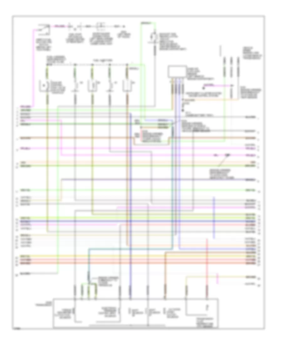
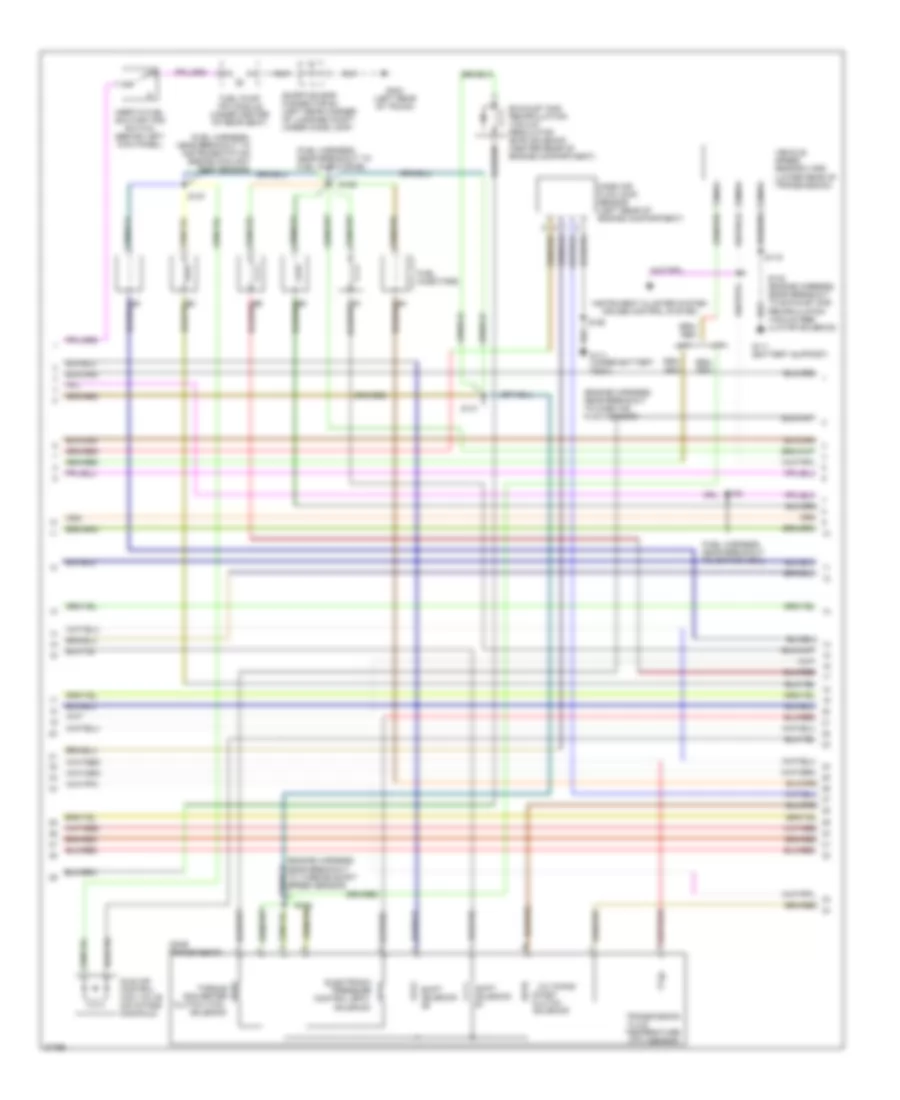
2.0L, Engine Performance Wiring Diagrams (1 of 4) for Ford Contour SE 1997

List of elements for 2.0L, Engine Performance Wiring Diagrams (1 of 4) for Ford Contour SE 1997:
- (behind power
- (engine harness, left side of engine compartment, near strut tower)
- (fuse box harness, on engine compartment fuse box)
- (under battery tray)
- 14s
- 15a
- 20a
- 91s
- A/t only
- Acc
- Air conditioning system
- Brake on/off (boo) switch (near top of brake pedal)
- C201
- C205
- C262
- C288
- Check engine ind.
- Cooling fans system
- Cps return
- Cps signal
- Data link conn +
- Data link conn -
- Data link connector #1 (left side of i/p)
- Data link power
- Engine compartment fuse box
- Evaporative emission (evap) canister purge valve (right rear of engine compartment)
- Evr solenoid
- Fuel pump monitor
- Fuel pump monitor (near left front strut, on fuel pump monitor)
- Fuel pump relay
- Fuse 13
- Fuse 14
- Fuse 24
- Fuse 4
- Fuse 9
- G106 (behind left headlamp)
- G111
- G123
- G203 (right kick panel)
- Gearshift lever unit (under center console)
- Ground
- Hi press cutoff
- Hi speed fan rel
- Hos2 #12 signal
- Hot at all times
- Ignition coil #1
- Ignition coil #2
- Ignition relay
- Ignition switch
- Instrument cluster
- Instrument interface module (left side of i/p)
- Intake air temp
- Interior fuse panel
- Lo speed fan rel
- Lock
- Maf return
- Main fuse 80a
- Nca
- Off
- P/s press sw
- Pcm output
- Pcm power relay
- Power distribution
- Powertrain control module (pcm) (behind power steering reservoir)
- Red
- Run
- S107
- S108
- S158
- S161
- S166
- S203 (fuse box harness, under left side of i/p, above fuse box)
- Sens sig return
- Shift sol #1
- Shift solenoid #2
- Shorting bar connector #1 (below i/p, left side of steering column)
- Start
- Tach
- Tachometer
- Temp sens
- Trans cntrl sw
- Trans temp
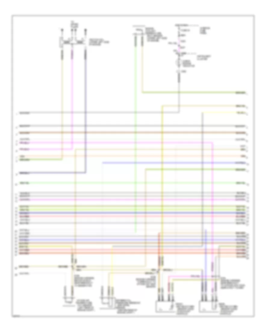
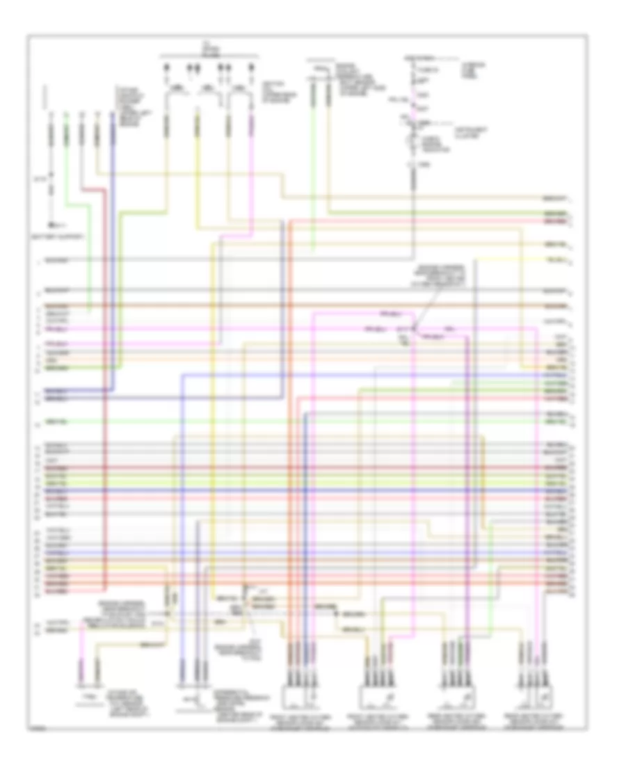
2.0L, Engine Performance Wiring Diagrams (2 of 4) for Ford Contour SE 1997
List of elements for 2.0L, Engine Performance Wiring Diagrams (2 of 4) for Ford Contour SE 1997:
- (engine harness, in breakout to to cd4e transaxle)
- (engine harness, near breakout to 42-pin conn, near strut tower)
- (fuel harness, near breakout to fuel inj #5) s129
- 3-2 timing/
- Cd4e transmission
- Clutch (tcc)
- Coast clutch
- Control (epc)
- Converter
- Electronic
- Exhaust gas recirculation vacuum regulator (evr) solenoid (center rear of engine compartment)
- Fluid
- Fuel injectors
- Fuel pump (fp) module (under center of rear seat)
- G111 (under battery tray)
- G404 (left rear of trunk)
- Idle air control (iac) valve (on intake manifold)
- Inertia fuel shutoff (ifs) switch (behind left kick panel)
- Instrument cluster system cruise control system
- Mass air flow (maf) sensor (left rear of engine compartment)
- Nca
- Near breakout to egr vacuum regulator sol)
- Pressure
- S133
- S153
- S154 (engine harness, near end of shield, toward breakout to vehicle speed sensor)
- S157 (engine harness, near breakout to intake air temp sensor)
- Shift
- Shorting bar connector #4 (left rear corner of luggage compt, under comb lamp)
- Solenoid
- Temperature (tft) sensor
- Torque
- Transmission
- Vehicle speed sensor (vss) (lower rear of transmission)
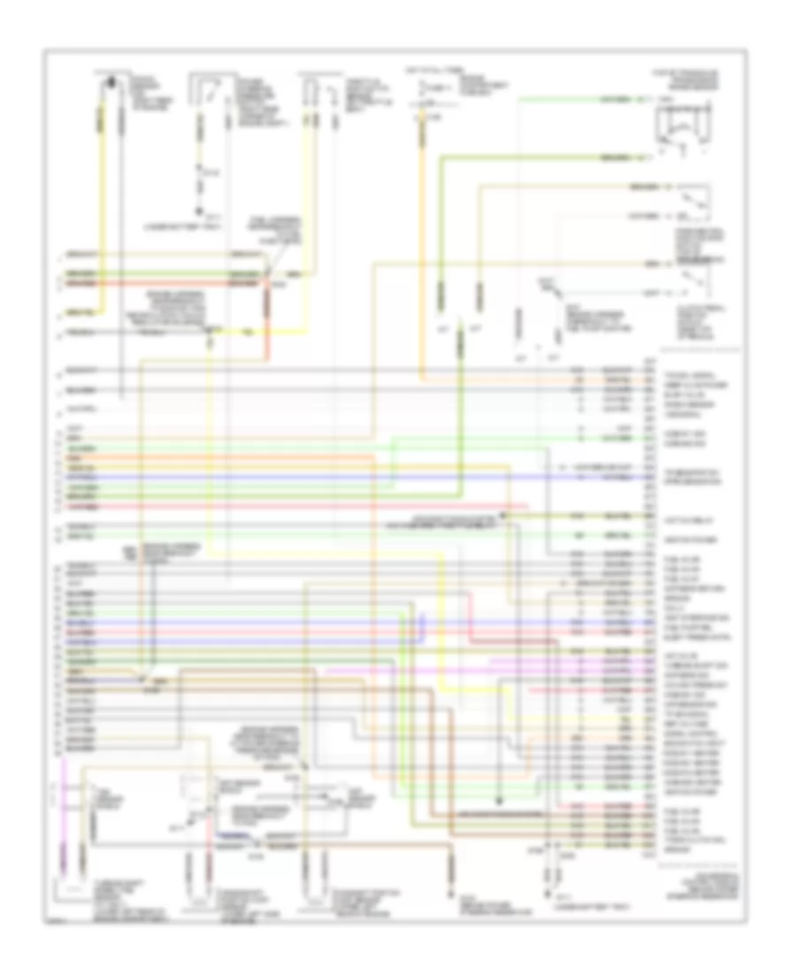
2.0L, Engine Performance Wiring Diagrams (3 of 4) for Ford Contour SE 1997
List of elements for 2.0L, Engine Performance Wiring Diagrams (3 of 4) for Ford Contour SE 1997:
- (center rear of
- (in exhaust
- (left rear of
- (upper left side
- 7.5a
- C262
- C283
- C290
- Check engine indicator
- Coolant
- Differential
- Egr (dpfe)
- Engine
- Engine compt.)
- Front
- Fuse 30
- Heated oxygen sensor (ho2s)
- Hot in run
- Ignition coil
- Instrument cluster
- Intake air
- Interior fuse panel
- Manifold)
- Nca
- Of engine)
- Pressure feedback
- Rear
- S156 (engine harness in breakout to intake air temp sensor)
- S164 (engine harness, near breakout to 42-pin black conn, near strut tower)
- S237
- Sensor
- Temperature (ect) sensor
- Temperature (iat) sensor
- To spark plugs
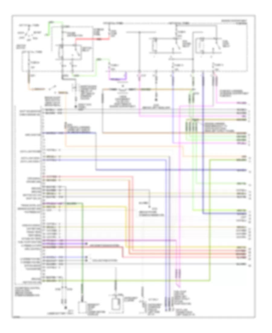
2.0L, Engine Performance Wiring Diagrams (4 of 4) for Ford Contour SE 1997
List of elements for 2.0L, Engine Performance Wiring Diagrams (4 of 4) for Ford Contour SE 1997:
- (a/t: near breakout to power steering pressure sensor) m/t: near breakout to pcm)
- (engine harness, near breakout to egr vacuum regulator sol)
- (engine harness, near breakout to pcm)
- (fuel harness, near breakout to fuel inj #3)
- (top of transaxle) transmission range sensor
- 29s
- 91s
- A/c high press sw
- A/t
- Air conditioning system
- Air conditioning system (a/c wide open throttle relay)
- Boo switch input
- Camshaft positon (cmp) sensor (upper left rear of engine)
- Ckp sensor shield
- Clutch pedal position switch (near top of pedals)
- Cmp sens return
- Cmp sens sig
- Cmp sensor shield
- Crankshaft position (ckp) sensor (lower left side of engine)
- Dpfe sensor sig
- Elect press cntrl
- Engine compartment fuse box
- Evap valve
- Fuel inj #1
- Fuel inj #2
- Fuel inj #3
- Fuel inj #4
- Fuel pump rel
- Fuse 11
- G111 (under battery tray)
- G123 (behind power steering reservoir)
- Ground
- Ho2s #11 heater
- Ho2s #11 sig
- Ho2s #12 heater
- Hot at all times
- Iac valve
- Ignition power
- Inst interface sig
- Keep alive power
- Knock sensor
- Knock sensor (ks) (right rear of engine)
- M/t
- Maf sensor sig
- Park/neutral position (pnp) switch (top of transmission)
- Power steering pressure sensor (on power steering line)
- Powertrain control module (behind power steering reservoir)
- Ref voltage
- S128
- S147 (engine harness, in breakout to fuel pump monitor)
- S148
- S149 (engine harness, near breakout to power steering pressure sensor)
- S150
- S158
- S162 (engine harness, near breakout to pcm)
- S163
- S166
- Signal control
- Tcc sol signal
- Throttle position (tp) sensor (on throttle body)
- Timing clutch sol
- Tp sig signal
- Tr sens/pnp sw
- Turbine shaft sig
- Turbine shaft speed (tss) sensor (a/t only) (lower left rear of engine compartment)
- Vss signal
- Wot a/c relay
2.5L
2.5L, Engine Performance Wiring Diagrams (1 of 4) for Ford Contour SE 1997
List of elements for 2.5L, Engine Performance Wiring Diagrams (1 of 4) for Ford Contour SE 1997:
- (behind power
- (engine harness, near breakout to 42-pin black conn, near left strut tower)
- (fuse box harness, on engine compartment fuse box)
- (right kick panel) g203
- (under battery tray)
- 14s
- 15a
- 20a
- 91s
- A/t only
- Acc
- Air conditioning system
- Brake on/off (boo) switch (near top of brake pedal)
- C201
- C205
- C262
- C288
- Check engine ind.
- Cooling fans system
- Cps return
- Cps signal
- Data link conn +
- Data link conn -
- Data link connector #1 (left side of i/p)
- Data link power
- Engine compartment fuse box
- Evr solenoid
- Fuel pump monitor
- Fuel pump monitor (near left front strut, on fuel pump monitor)
- Fuel pump relay
- Fuse 13
- Fuse 14
- Fuse 24
- Fuse 4
- Fuse 9
- G106 (behind left headlamp)
- G111
- G123
- Gearshift lever unit (under center console)
- Ground
- Hi press cutoff
- Hi speed fan rel
- Hos2 #12 signal
- Hot at all times
- Ignition coil #1
- Ignition coil #2
- Ignition relay
- Ignition switch
- Imrc control
- Imrc monitor
- Instrument cluster
- Instrument interface module (left side of i/p)
- Intake air temp
- Interior fuse panel
- Lo speed fan rel
- Lock
- Maf return
- Main fuse 80a
- Nca
- Off
- P/s press sw
- Pcm output
- Pcm power relay
- Power distribution
- Powertrain control module (pcm) (behind power steering reservoir)
- Red
- Run
- S158
- S161
- S166
- S203 (fuse box harness, under left side of i/p, above fuse box)
- Sensor sig return
- Shift sol #1
- Shift solenoid #2
- Shorting bar connector #1 (below i/p, left side of steering column)
- Start
- Tach
- Tachometer
- Temp sens
- Trans cntrl sw
- Trans temp
- Vapor management valve (vmv) (right rear of engine compartment)
2.5L, Engine Performance Wiring Diagrams (2 of 4) for Ford Contour SE 1997
List of elements for 2.5L, Engine Performance Wiring Diagrams (2 of 4) for Ford Contour SE 1997:
- (engine harness, near breakout to mass air flow sensor)
- (fuel harness, near breakout to fuel injector #5)
- (fuel harness, near breakout to ignition coil)
- 3-2 timing/
- A/t
- Cd4e
- Clutch (tcc)
- Coast clutch
- Control (epc)
- Converter
- Electronic
- Exhaust gas recirculation vacuum regulator (evr) solenoid (center rear of engine compartment)
- Fluid
- Fuel injectors
- Fuel pump (fp) module (under center of rear seat)
- G111 (battery support)
- G111 (under battery tray)
- G404 (left rear of trunk)
- Idle air control (iac) valve (on intake manifold)
- Inertia fuel shutoff (ifs) switch (behind left kick panel)
- Instrument cluster system cruise control system
- M/t
- Mass air flow (maf) sensor (left rear of engine compartment)
- Nca
- Pressure
- Recirculation vacuum reg- ulator solenoid)
- S119
- S127
- S129
- S133
- S141
- S158
- Shift
- Shorting bar connector #4 (left rear corner of luggage compt, under comb lamp)
- Solenoid
- Temperature (tft) sensor
- Torque
- Transmission
- Vehicle speed sensor (vss) (lower rear of transmission)
2.5L, Engine Performance Wiring Diagrams (3 of 4) for Ford Contour SE 1997
List of elements for 2.5L, Engine Performance Wiring Diagrams (3 of 4) for Ford Contour SE 1997:
- (battery support)
- (center rear of
- (engine harness, near breakout to exhaust gas recirculation vacuum regulator solenoid)
- (engine harness, near breakout to front heated oxygen sensor #11)
- (left rear of
- (upper left side
- 7.5a
- C262
- C283
- C290
- Check engine indicator
- Coolant
- Differential
- Egr (dpfe)
- Engine
- Engine compt.)
- Front heated oxygen sensor (ho2s) #11 (in exhaust manifold)
- Front heated oxygen sensor (ho2s) #21 (in exhaust manifold)
- Fuse 30
- G111
- Hot in run
- Ignition coil (upper rear of engine)
- Instrument cluster
- Intake air
- Intake manifold runner (imrc) (upper left rear of engine)
- Interior fuse panel
- M/t
- Nca
- Of engine)
- Pressure feedback
- Rear heated oxygen sensor (ho2s) #12 (in exhaust manifold)
- Rear heated oxygen sensor (ho2s) #22 (in exhaust manifold)
- S117
- S119
- S137 (engine harness, near breakout to pcm)
- S144
- S237
- Sensor
- Temperature (ect) sensor
- Temperature (iat) sensor
- To spark plugs
2.5L, Engine Performance Wiring Diagrams (4 of 4) for Ford Contour SE 1997
List of elements for 2.5L, Engine Performance Wiring Diagrams (4 of 4) for Ford Contour SE 1997:
- (engine harness, near breakout to exhaust gas recirculation vacuum regulator solenoid) s143
- (engine harness, near breakout to pcm)
- (engine harness, near breakout to: a/t-power steering pressure sensor,
- (fuel harness, near breakout to fuel injector #2)
- (top of transaxle) transmission range sensor
- (under battery tray)
- 29s
- 91s
- A/c high press sw
- A/t
- Air conditioning system
- Air conditioning system (a/c wide open throttle relay)
- Boo switch input
- Camshaft positon (cmp) sensor (upper left rear of engine)
- Ckp sensor shield
- Clutch pedal position switch (near top of pedals)
- Cmp sens return
- Cmp sens sig
- Cmp sensor shield
- Coil c
- Crankshaft position (ckp) sensor (lower left side of engine)
- Dpfe sensor sig
- Elect press cntrl
- Engine compartment fuse box
- Evap valve
- Fuel inj #1
- Fuel inj #2
- Fuel inj #3
- Fuel inj #4
- Fuel inj #5
- Fuel inj #6
- Fuel pump rel
- Fuse 11
- G111
- G123 (behind power steering reservoir)
- Ground
- Ho2s #11 heater
- Ho2s #11 sig
- Ho2s #12 heater
- Ho2s #21 heater
- Ho2s #21 sig
- Ho2s #22 heater
- Ho2s #22 sig
- Hot at all times
- Iac valve
- Ignition power
- Inst interface sig
- Keep alive power
- Knock sensor
- Knock sensor (ks) (right rear of engine)
- M/t
- M/t-pcm)
- Maf sensor sig
- Park/neutral position (pnp) switch (top of transmission)
- Power steering pressure switch (right rear corner of engine compt.)
- Powertrain control module (behind power steering reservoir)
- Ref voltage
- S111
- S112
- S119
- S128
- S138
- S147 (engine harness, in breakout to fuel pump monitor)
- S158
- S162
- S163
- S166
- S168
- Signal control
- Tcc sol signal
- Throttle position (tp) sensor (on throttle body)
- Timing clutch sol
- Tp sig signal
- Tr sens/pnp sw
- Turbine shaft sig
- Turbine shaft speed (tss) sensor (a/t only) (lower left rear of engine compartment)
- Vss signal
- Wot a/c relay