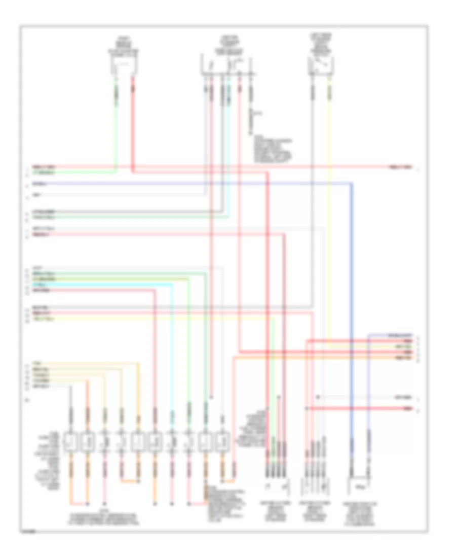
ENGINE PERFORMANCE
5.4L
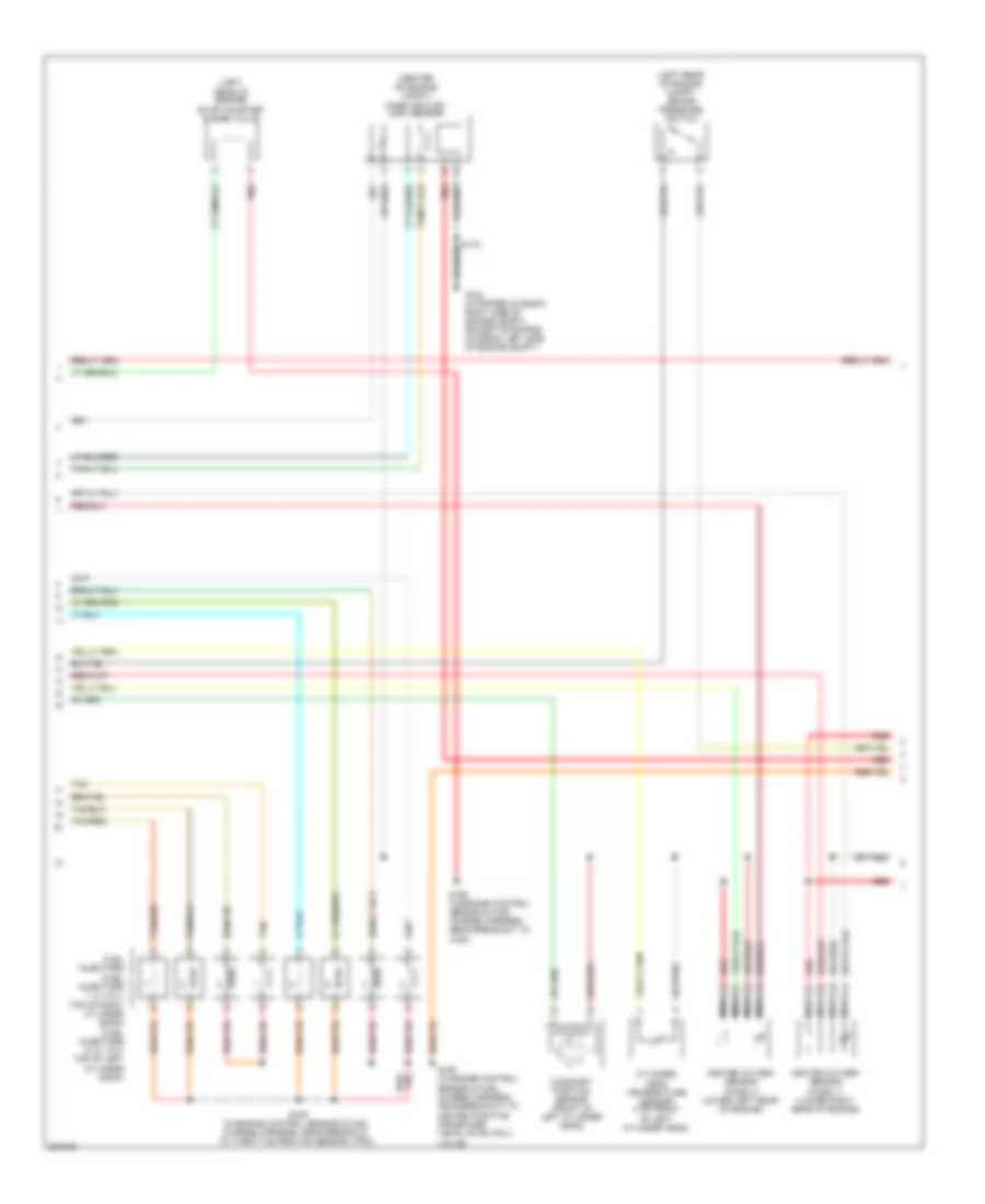
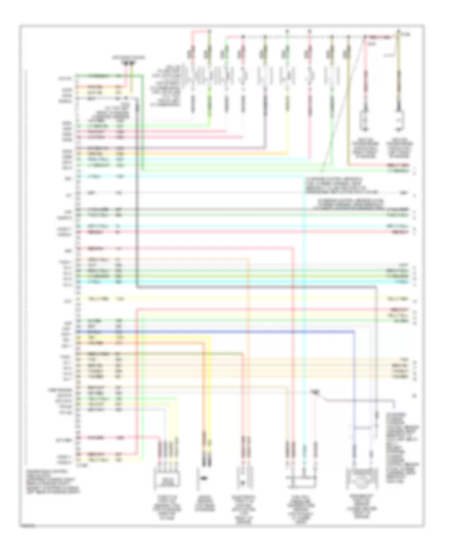
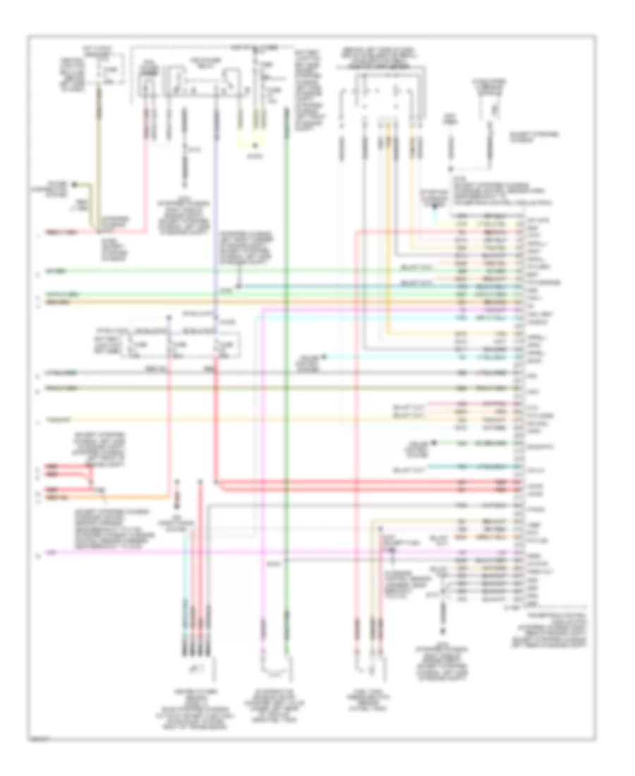
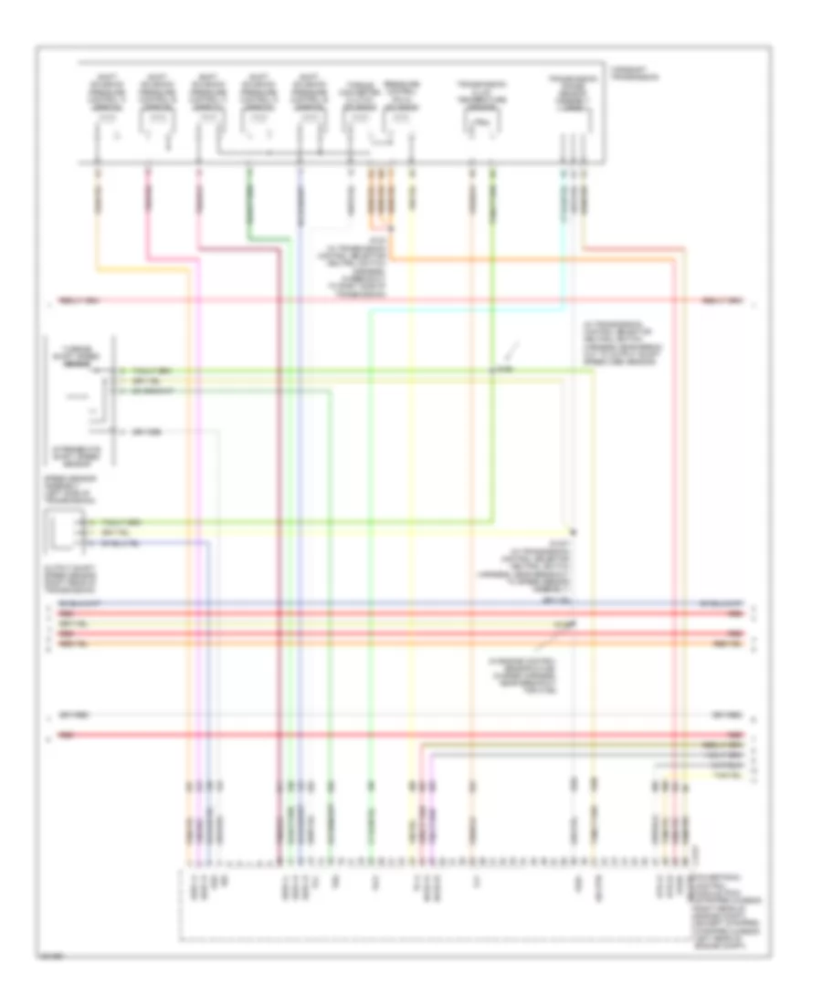
5.4L, Engine Performance Wiring Diagram, with Torqshift (1 of 5) for Ford Cutaway E250 2008

List of elements for 5.4L, Engine Performance Wiring Diagram, with Torqshift (1 of 5) for Ford Cutaway E250 2008:
- (in engine control sensor & fuel charge harness, near breakout to heated positive crankcase ventilation (pcv) valve)
- (in engine control sensor & fuel charge harness, near breakout to throttle position sensor (tps))
- (stripped chassis: in engine control sensor harness, near breakout to auxiliary relay box 1) (except stripped chassis: in engine control sensor & fuel charge harness, near breakout for c192)
- Accr
- Accs
- Air conditioning system
- Bpp
- C175e
- Cd1a
- Cd2d
- Cd3b
- Cd4g
- Cd5f
- Cd6e
- Cd7c
- Cd8h
- Cht
- Ckp +
- Ckp -
- Cmp
- Coil on plugs (cop) (coil on plugs 1, 2, 3, & 4: top of right cylinder bank) (coil on plugs 5, 6, 7 & 8: top of left cylinder bank)
- Crankshaft position sensor (lower center front of engine)
- Electronic throttle control (etc) motor (top front of engine)
- Etc ref
- Etc rtn
- Frp
- Frt
- Fuel rail pressure/ temperature sensor (top of right cylinder head)
- Ho2s-11
- Ho2s-21
- Iat
- Ignition transformer capacitor 1 (left front of engine)
- Ignition transformer capacitor 2 (right front of engine)
- Inj 1
- Inj 2
- Inj 3
- Inj 4
- Inj 5
- Inj 6
- Inj 7
- Inj 8
- Knock sensor (top rear of engine)
- Ks1 +
- Ks1 -
- Maf
- Mafrtn
- Nca
- Powertrain control module (pcm) (stripped chassis: right rear of engine compt) (except stripped chassis: left rear of engine compt)
- Red/pnk
- S103 (at top left front of engine, in engine harness)
- S136
- S156
- S161
- Shield
- Sig rtn
- Solid state
- Tacm +
- Tacm -
- Tan
- Tan/red
- Throttle position sensor (tps) (top of engine, near air intake)
- Tp1-ns
- Tp2-ns
- Vmv-cc
- Vref engine
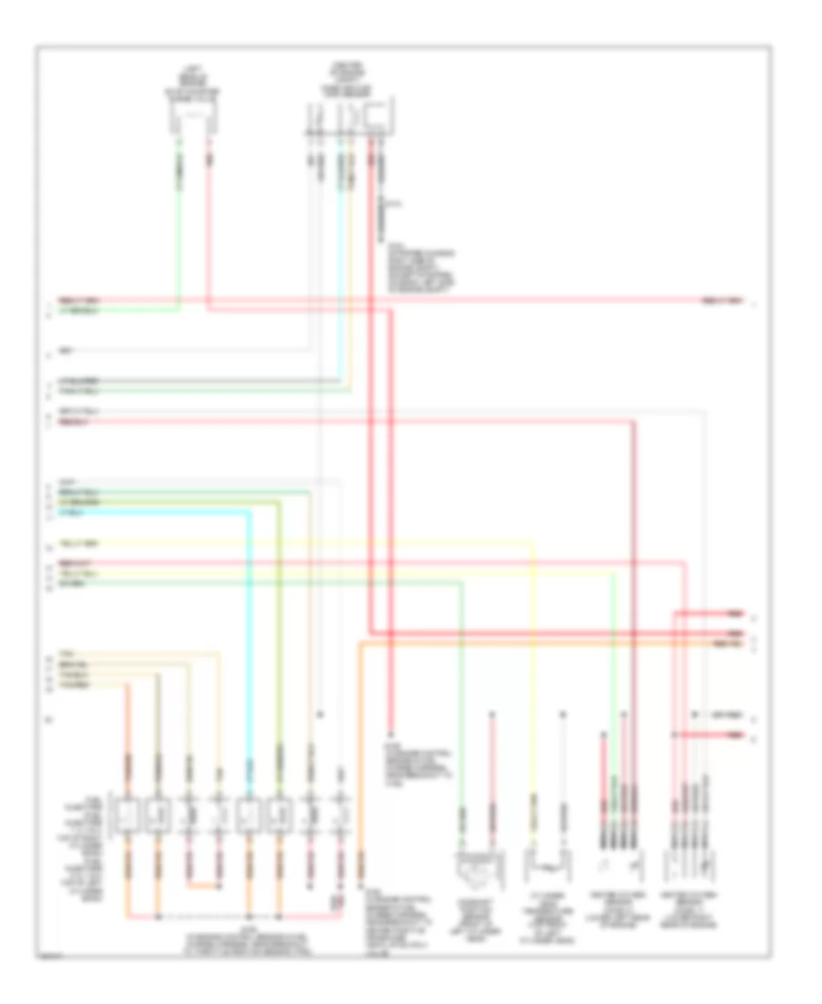
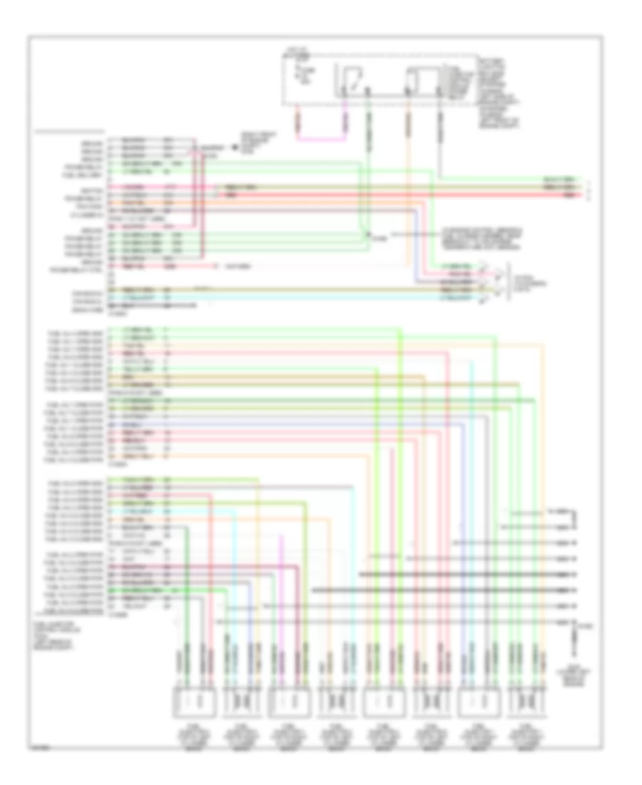
5.4L, Engine Performance Wiring Diagram, with Torqshift (2 of 5) for Ford Cutaway E250 2008
List of elements for 5.4L, Engine Performance Wiring Diagram, with Torqshift (2 of 5) for Ford Cutaway E250 2008:
- (center of engine compt) mass air flow (maf) sensor
- (left rear of engine compt) brake pressure switch
- (left rear of engine) evap canister purge valve
- Camshaft position sensor (front of left cylinder head)
- Cylinder- head temperature sensor (top front of left cylinder head)
- Fuel injectors (fuel injectors 1, 2, 3 & 4: top of right cylinder bank) (fuel injectors 5, 6, 7 & 8: top of left cylinder bank)
- G104 (stripped chassis: right side of engine compt) (except stripped chassis: left side of engine compt)
- Heated oxygen sensor (ho2s) 11 (lower right rear of engine)
- Heated oxygen sensor (ho2s) 21 (lower left rear of engine)
- Nca
- Red
- S155 (in engine control sensor & fuel charge harness, near breakout to throttle position sensor (tps))
- S159 (in engine control sensor & fuel charge harness, near breakout to c192)
- S160 (in engine control sensor & fuel charge harness, near breakout to heated positive crankcase ventilation (pcv) valve)
- Tan
- Tan/red
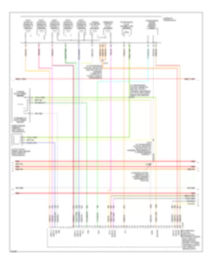
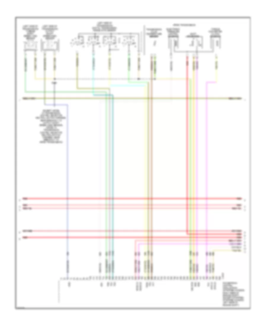
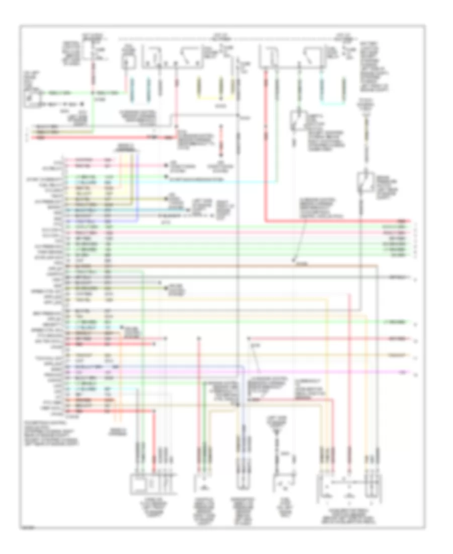
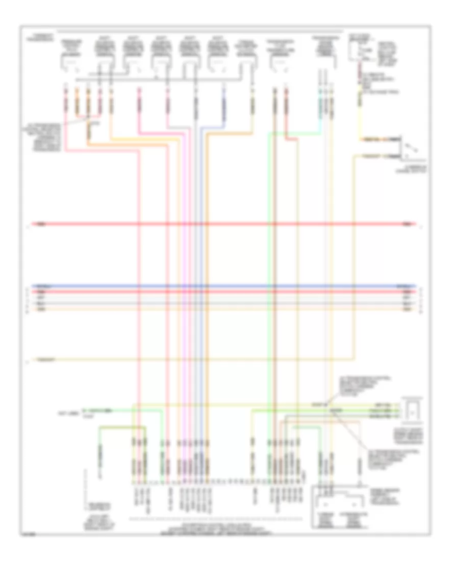
5.4L, Engine Performance Wiring Diagram, with Torqshift (3 of 5) for Ford Cutaway E250 2008
List of elements for 5.4L, Engine Performance Wiring Diagram, with Torqshift (3 of 5) for Ford Cutaway E250 2008:
- (in engine control sensor & fuel charge harness, near breakout for c192)
- (in transmission control selector neutral switch harness, in breakout to right side of transmission)
- (in transmission control selector neutral switch harness, near break- out to output shaft speed (oss) sensor) s198
- C175t
- Control module (pcm) (stripped chassis: right rear of engine compt) (except stripped stripped chassis: left rear of engine compt)
- Ho2s-12
- Ho2s-22
- Htr-12
- Htr-22
- Intermediate shaft speed sensor
- Iss
- Oss
- Output shaft speed (oss) sensor (right rear of transmission)
- Pc-a
- Powertrain sig rtn
- Pressure control (pc-a) solenoid
- Red
- S1037 (in transmission control selector neutral switch harness, near breakout to speed sensor assembly)
- S123
- S139
- Shift solenoid pressure control a (sspc-a)
- Shift solenoid pressure control b (sspc-b)
- Shift solenoid pressure control c (sspc-c)
- Shift solenoid pressure control d (sspc-d)
- Shift solenoid pressure control e (sspc-e)
- Sig rtn
- Speed sensor assembly (left side of transmission)
- Sspc-a
- Sspc-b
- Sspc-c
- Sspc-d
- Sspc-e
- Tcc
- Tft
- Torqshift transmission
- Torque converter clutch solenoid
- Tr-p
- Transmission fluid temperature sensor
- Transmission range sensor assembly (tr-p)
- Tss
- Turbine shaft speed sensor
- Vpwr
- Vref
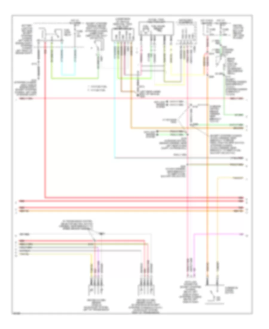
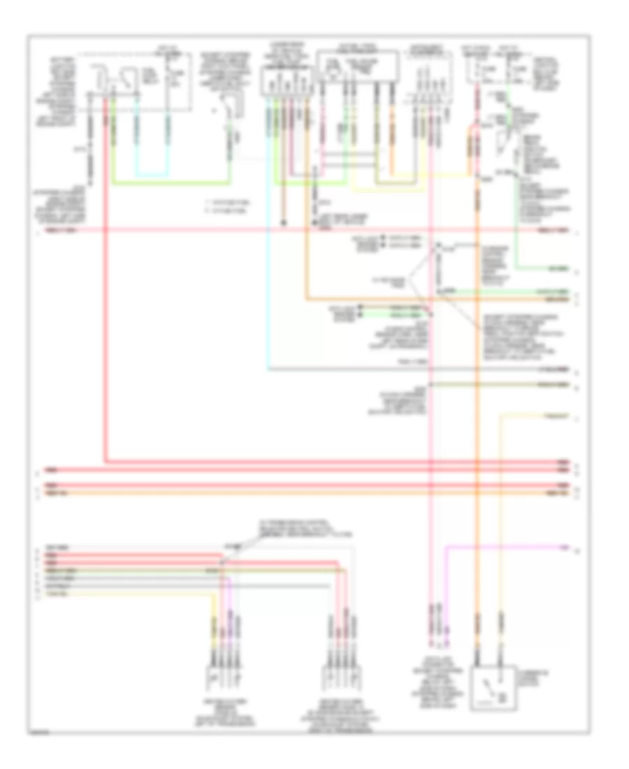
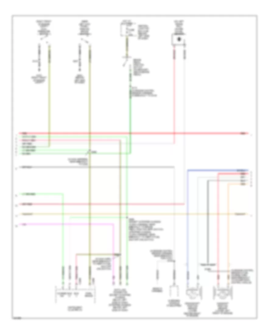
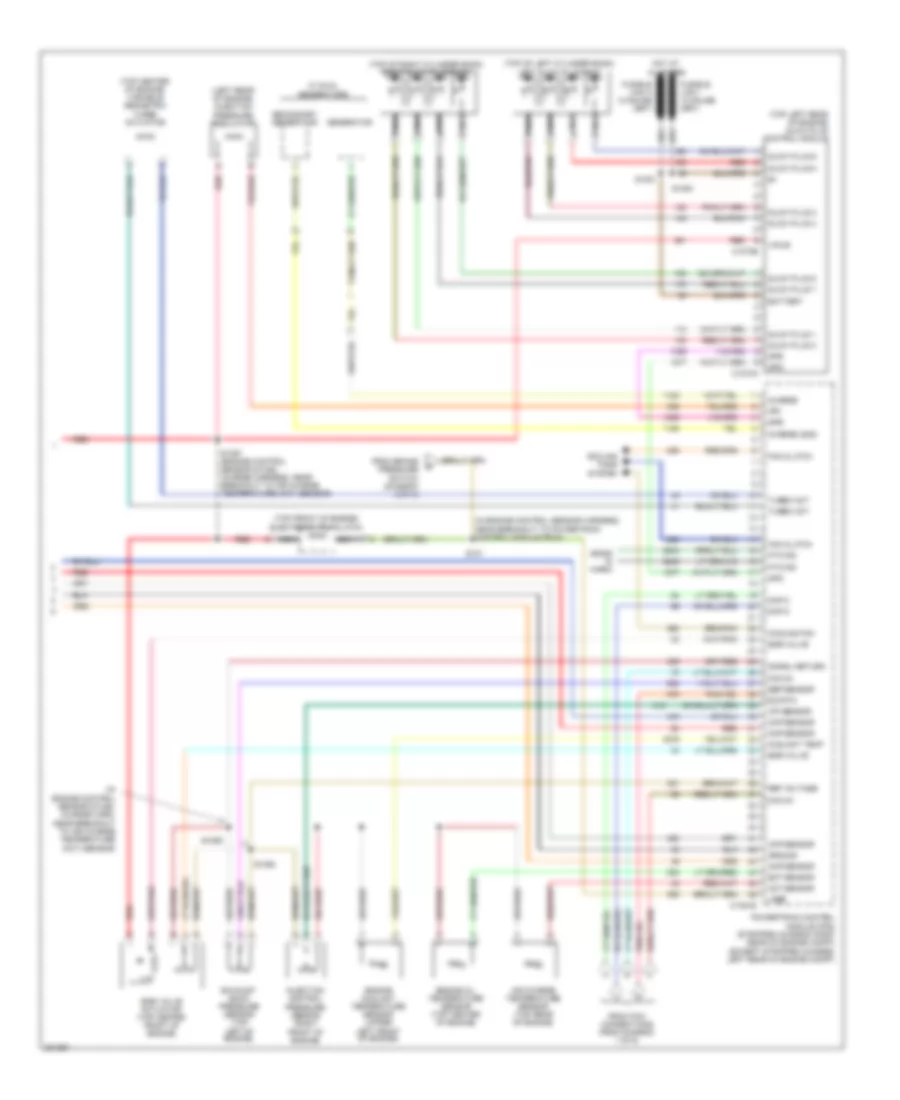
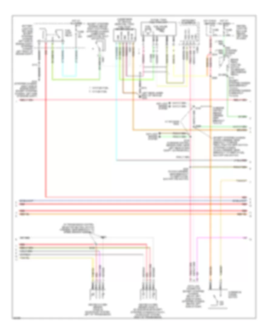
5.4L, Engine Performance Wiring Diagram, with Torqshift (4 of 5) for Ford Cutaway E250 2008
List of elements for 5.4L, Engine Performance Wiring Diagram, with Torqshift (4 of 5) for Ford Cutaway E250 2008:
- (except stripped chassis: behind right kick panel) (stripped chassis: under dash) inertia fuel shut- off switch
- (except stripped chassis: in main harness, near breakout to brake pedal position (bpp) switch) (stripped chassis: in main harness, near breakout to inertia fuel shutoff (ifs) switch)
- (in engine control sensor harness, near breakout to c110)
- (in fuel tank) fuel tank unit
- (in transmission control selector neutral switch harness, near breakout to speed sensor assembly)
- (left rear under- body of vehicle) g300
- (under rear of vehicle, near fuel tank) fuel pump driver module
- Anti-lock brakes system
- Battery junction box (bjb) (except stripped chassis: left side of engine compt) (stripped chassis: left front of engine compt)
- Brake pedal position switch (on bracket, above brake pedal)
- Can +
- Can -
- Central junction box (cjb) (behind left side of dash)
- Chassis only)
- Data link connector (except stripped chassis: below left side of dash) (stripped chassis: behind left side of dash)
- Fp pwr
- Fp rtn
- Fpm
- Fuel gauge sensor
- Fuel lvl +
- Fuel lvl -
- Fuel pump
- Fuel pump relay
- Fuse 10a
- Fuse 15a
- Fuse 20a
- G104 (stripped chassis: right side of engine compt) (except stripped chassis: left side of engine compt)
- Gnd
- Heated oxygen sensor (ho2s) 12 (e-150/e-250/e-350 except stripped chassis/cutaway) (on exhaust system, right of transmission)
- Heated oxygen sensor (ho2s) 22 (on exhaust system, left of transmission)
- Hot at all times
- Hot in run or start
- Ifs in
- Instrument cluster (ic)
- Nca
- O/d off
- Overdrive cancel switch
- Red
- S100
- S102
- S146
- S148 (in engine control sensor harness, near left rear of eng compt, on frame rail)
- S172
- S174 (except stripped chassis: near breakout to g101) (stripped chassis: in breakout to c219)
- S216
- S228 (in main harness, near breakout to inertia fuel shutoff (ifs) switch)
- S260
- S269
- S312
- W/ advance trac
- W/ flex fuel
- W/o flex fuel
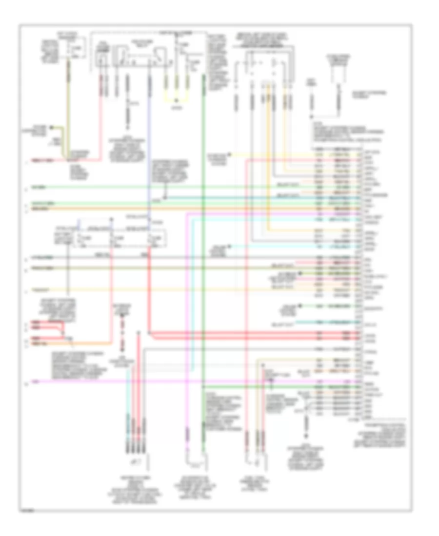
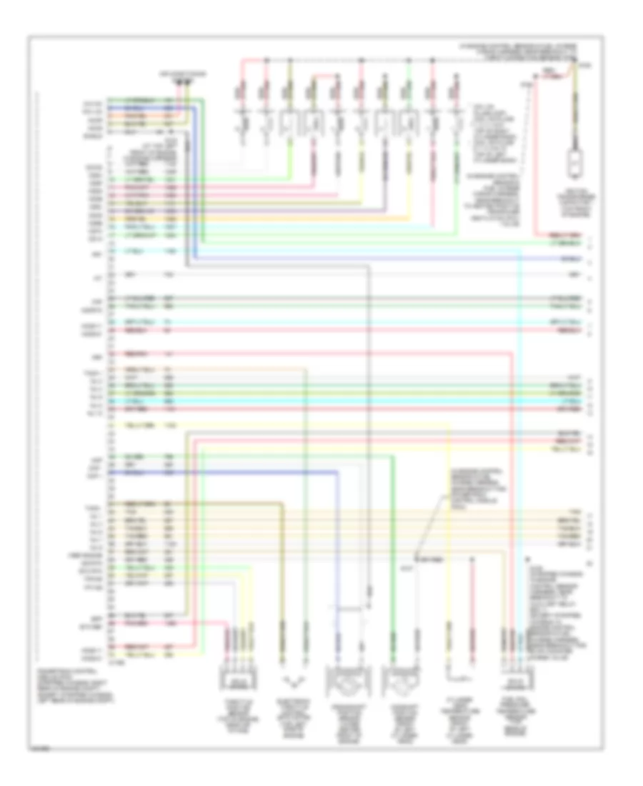
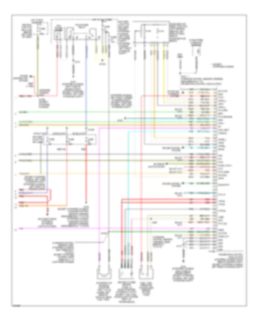
5.4L, Engine Performance Wiring Diagram, with Torqshift (5 of 5) for Ford Cutaway E250 2008
List of elements for 5.4L, Engine Performance Wiring Diagram, with Torqshift (5 of 5) for Ford Cutaway E250 2008:
- (behind left side of dash, above accelerator pedal) accelerator pedal position (app) sensor
- (except stripped chassis: in engine control sensor harness, near breakout to c140) (stripped chassis: in engine control sensor harness, near breakout to c219)
- (except stripped chassis: left side of engine compt) (stripped chassis: left front of engine compt)
- (if equipped) overhead console
- (in engine control sensor harness, near breakout to c110)
- (not used)
- (stripped chassis) s127
- (stripped chassis: left front corner of engine compt) (except stripped chassis: left side of engine compt)
- 4x4 lo
- Aft std
- Air conditioning system
- App1
- App2
- App3
- Appa_+
- Appa_-
- Appb_+
- Appb_-
- Battery junction box (bjb)
- Battery junction box (bjb) (except stripped chassis: left side of engine compt) (stripped chassis: left front of engine compt)
- Bpp
- C175b
- Can +
- Can -
- Can vent
- Central junction box (cjb) (behind left side of dash)
- Cruise control system
- Cto
- Evaporative emission (evap) canister vent valve (under left rear of vehicle, near fuel tank)
- Except stripped chassis
- Exterior lights system
- Feps
- Fpm
- Ftpt
- Fuel tank pressure (ftp) sensor (in fuel tank)
- Fuse 10a
- Fuse 15a
- Fuse 20a
- Fuse 30a
- Fuse 5a
- G100
- G104 (stripped chassis: right side of engine compt) (except stripped chassis: left side of engine compt)
- Gnd
- Heated oxygen sensor (ho2s) 12 (e-350 stripped chassis/ cutaway except flex fuel) (on exhaust system, right of transmission)
- Ho2s-23
- Hot at all times
- Hot in run or start
- Htr-23
- Ka pwr
- Nca
- Od cncl
- P/n
- Park out
- Pcm power diode
- Pcm power relay
- Power distribution system
- Powertrain control module (pcm) (stripped chassis: right rear of engine compt) (except stripped chassis: left rear of engine compt)
- Pto engage
- Pto ind
- Pto mode
- Pto rpm
- Red
- Red/pnk
- Rtn
- Rvrs lp rly
- S1021 (in engine control sensor harn, stripped chassis: neat breakout to g101) except stripped chassis: near breakout to customer access)
- S1033
- S1035
- S1065 (except stripped chassis)
- S135 (except stripped chassis) (in engine control sensor harness, near breakout to powertrain control module (pcm))
- S142
- S157 (except flex fuel)
- S172
- Sccs
- Sccs rtn
- Smr
- Starting/ charging system
- Tan
- Vpwr
- Vref
5.4L, Engine Performance Wiring Diagram, without Torqshift (1 of 5) for Ford Cutaway E250 2008
List of elements for 5.4L, Engine Performance Wiring Diagram, without Torqshift (1 of 5) for Ford Cutaway E250 2008:
- (in engine control sensor & fuel charge harness, near breakout to heated positive crankcase ventilation (pcv) valve)
- (in engine control sensor & fuel charge harness, near breakout to throttle position sensor (tps))
- (stripped chassis: in engine control sensor harness, near breakout to auxiliary relay box 1) (except stripped chassis: in engine control sensor & fuel charge harness, near breakout for c192)
- Accr
- Accs
- Air conditioning system
- C175e
- Cd1a
- Cd2d
- Cd3b
- Cd4g
- Cd5f
- Cd6e
- Cd7c
- Cd8h
- Cht
- Ckp +
- Ckp -
- Cmp
- Coil on plugs (cop) (coil on plugs 1, 2, 3, & 4: top of right cylinder bank) (coil on plugs 5, 6, 7 & 8: top of left cylinder bank)
- Crankshaft position sensor (lower center front of engine)
- Electronic throttle control (etc) motor (top front of engine)
- Etc ref
- Etc rtn
- Frp
- Frt
- Fuel rail pressure/ temperature sensor (top of right cylinder head)
- Ho2s-11
- Ho2s-21
- Iat
- Ignition transformer capacitor 1 (left front of engine)
- Ignition transformer capacitor 2 (right front of engine)
- Inj 1
- Inj 2
- Inj 3
- Inj 4
- Inj 5
- Inj 6
- Inj 7
- Inj 8
- Knock sensor (top rear of engine)
- Ks1 +
- Ks1 -
- Maf
- Mafrtn
- Nca
- Powertrain control module (pcm) (stripped chassis: right rear of engine compt) (except stripped chassis: left rear of engine compt)
- Red/pnk
- S103 (at top left front of engine, in engine harness)
- S136
- S156
- S161
- Shield
- Sig rtn
- Solid state
- Tacm +
- Tacm -
- Tan
- Tan/red
- Throttle position sensor (tps) (top of engine, near air intake)
- Tp1-ns
- Tp2-ns
- Vmv-cc
- Vref engine
5.4L, Engine Performance Wiring Diagram, without Torqshift (2 of 5) for Ford Cutaway E250 2008
List of elements for 5.4L, Engine Performance Wiring Diagram, without Torqshift (2 of 5) for Ford Cutaway E250 2008:
- (center of engine compt) mass air flow (maf) sensor
- (left rear of engine) evap canister purge valve
- Camshaft position sensor (front of left cylinder head)
- Cylinder- head temperature sensor (top front of left cylinder head)
- Fuel injectors (fuel injectors 1, 2, 3 & 4: top of right cylinder bank) (fuel injectors 5, 6, 7 & 8: top of left cylinder bank)
- G104 (stripped chassis: right side of engine compt) (except stripped chassis: left side of engine compt)
- Heated oxygen sensor (ho2s) 11 (lower right rear of engine)
- Heated oxygen sensor (ho2s) 21 (lower left rear of engine)
- Nca
- Red
- S155 (in engine control sensor & fuel charge harness, near breakout to throttle position sensor (tps))
- S159 (in engine control sensor & fuel charge harness, near breakout to c192)
- S160 (in engine control sensor & fuel charge harness, near breakout to heated positive crankcase ventilation (pcv) valve)
- Tan
- Tan/red
5.4L, Engine Performance Wiring Diagram, without Torqshift (3 of 5) for Ford Cutaway E250 2008
List of elements for 5.4L, Engine Performance Wiring Diagram, without Torqshift (3 of 5) for Ford Cutaway E250 2008:
- (except 4r75e: in transmission control selector neutral switch harness, near breakout to output shaft speed (oss) sensor) (4r75e: in transmission control selector neutral switch harness, near breakout to 4r75e transmission)
- (left side of transmission) digital transmission range (dtr) sensor
- (left side of transmission) output shaft speed (oss) sensor
- (left side of transmission) turbine shaft speed (tss) sensor
- 4r75e transmission
- C175t
- Electronic pressure control solenoid
- Epc
- Ho2s-12
- Ho2s-22
- Htr-12
- Htr-22
- Oss
- Powertrain control module (pcm) (stripped chassis: right rear of engine compt) (except stripped stripped chassis: left rear of engine compt)
- Red
- S198
- Shift solenoids
- Sig rtn
- Ssa
- Ssb
- Tcc
- Tft
- Torque converter clutch solenoid
- Tr1
- Tr2
- Tr3a
- Tr4
- Transmission fluid temperature sensor
- Tss
5.4L, Engine Performance Wiring Diagram, without Torqshift (4 of 5) for Ford Cutaway E250 2008
List of elements for 5.4L, Engine Performance Wiring Diagram, without Torqshift (4 of 5) for Ford Cutaway E250 2008:
- (except stripped chassis: behind right kick panel) (stripped chassis: under dash) inertia fuel shut- off switch
- (except stripped chassis: in main harness, near breakout to brake pedal position (bpp) switch) (stripped chassis: in main harness, near breakout to inertia fuel shutoff (ifs) switch)
- (in engine control sensor harness, near breakout to c110)
- (in fuel tank) fuel tank unit
- (in transmission control selector neutral switch harness, near breakout to c192)
- (left rear under- body of vehicle) g300
- (under rear of vehicle, near fuel tank) fuel pump driver module
- Anti-lock brakes system
- Battery junction box (bjb) (except stripped chassis: left side of engine compt) (stripped chassis: left front of engine compt)
- Brake pedal position switch (on bracket, above brake pedal)
- Can +
- Can -
- Central junction box (cjb) (behind left side of dash)
- Data link connector (except stripped chassis: below left side of dash) (stripped chassis: behind left side of dash)
- Fp pwr
- Fp rtn
- Fpm
- Fuel gauge sensor
- Fuel lvl +
- Fuel lvl -
- Fuel pump
- Fuel pump relay
- Fuse 10a
- Fuse 15a
- Fuse 20a
- G104 (stripped chassis: right side of engine compt) (except stripped chassis: left side of engine compt)
- Gnd
- Heated oxygen sensor (ho2s) 12 (e-150/e-250/e-350 except stripped chassis/cutaway) (on exhaust system, right of transmission)
- Heated oxygen sensor (ho2s) 22 (on exhaust system, left of transmission)
- Hot at all times
- Hot in run or start
- Ifs in
- Instrument cluster (ic)
- Nca
- O/d off
- Only)
- Overdrive cancel switch
- Red
- S100
- S102
- S146
- S148 (in eng control sensor harn, near left rear of eng compt, on frame rail)
- S172
- S174 (except stripped chassis: near breakout to g101) (stripped chassis: in breakout to c219)
- S216
- S228 (in main harness, near breakout to inertia fuel shutoff (ifs) switch)
- S260
- S269
- S312
- W/ advance trac
- W/ flex fuel
- W/o flex fuel
5.4L, Engine Performance Wiring Diagram, without Torqshift (5 of 5) for Ford Cutaway E250 2008
List of elements for 5.4L, Engine Performance Wiring Diagram, without Torqshift (5 of 5) for Ford Cutaway E250 2008:
- (behind left side of dash, above accelerator pedal) accelerator pedal position (app) sensor
- (except stripped chassis: in engine control sensor harness, near breakout to c140) (stripped chassis: in engine control sensor harness, near breakout to c219)
- (except stripped chassis: left side of engine compt) (stripped chassis: left front of engine compt)
- (if equipped) overhead console
- (in engine control sensor harness, near breakout to c110)
- (not used)
- (stripped chassis) s127
- (stripped chassis: left front corner of engine compt) (except stripped chassis: left side of engine compt)
- 4x4 lo
- Aft std
- Air conditioning system
- App1
- App2
- App3
- Appa_+
- Appa_-
- Appb_+
- Appb_-
- Battery junction box (bjb)
- Battery junction box (bjb) (except stripped chassis: left side of engine compt) (stripped chassis: left front of engine compt)
- Bpp
- C175b
- Can +
- Can -
- Can vent
- Central junction box (cjb) (behind left side of dash)
- Cruise control system
- Cto
- Evaporative emission (evap) canister vent valve (under left rear of vehicle, near fuel tank)
- Except stripped chassis
- Feps
- Fpm
- Ftpt
- Fuel tank pressure (ftp) sensor (in fuel tank)
- Fuse 10a
- Fuse 15a
- Fuse 20a
- Fuse 30a
- Fuse 5a
- G100
- G104 (stripped chassis: right side of engine compt) (except stripped chassis: left side of engine compt)
- Gnd
- Heated oxygen sensor (ho2s) 12 (e-350 stripped chassis/ cutaway except flex fuel) (on exhaust system, right of transmission)
- Ho2s-23
- Hot at all times
- Hot in run or start
- Htr-23
- Ka pwr
- Nca
- Od cncl
- Park out
- Pcm power diode
- Pcm power relay
- Power distribution system
- Powertrain control module (pcm) (stripped chassis: right rear of engine compt) (except stripped chassis: left rear of engine compt)
- Pto engage
- Pto ind
- Pto mode
- Pto rpm
- Red
- Red/pnk
- Rtn
- S1021
- S1033
- S1035
- S1065 (except stripped chassis)
- S135 (except stripped chassis) (in engine control sensor harn, near breakout to powertrain control module (pcm))
- S142
- S157 (except flex fuel)
- S172
- Sccs
- Sccs rtn
- Smr
- Starting/ charging system
- Tan
- Vpwr
- Vref
- Vss
6.0L DIESEL
6.0L Diesel, Engine Performance Wiring Diagram (1 of 5) for Ford Cutaway E250 2008
List of elements for 6.0L Diesel, Engine Performance Wiring Diagram (1 of 5) for Ford Cutaway E250 2008:
- (in engine control sensor & fuel charge harness, near breakout to air charge temperature (act) sensor)
- (pins 11-21 not used)
- (pins 9-16 not used)
- (right front of engine compt) g106
- Battery junction box (bjb) (except stripped chassis: left side of engine compt) (stripped chassis: left front of engine compt)
- C1388a
- C1388b
- C1388c
- Can bus 2h
- Can bus 2l
- Cylinder id
- Drain wire
- Fuel delivery
- Fuel inj 1 close gnd
- Fuel inj 1 close pwr
- Fuel inj 1 open gnd
- Fuel inj 1 open pwr
- Fuel inj 2 close gnd
- Fuel inj 2 close pwr
- Fuel inj 2 open gnd
- Fuel inj 2 open pwr
- Fuel inj 3 close gnd
- Fuel inj 3 close pwr
- Fuel inj 3 open gnd
- Fuel inj 3 open pwr
- Fuel inj 4 close gnd
- Fuel inj 4 close pwr
- Fuel inj 4 open gnd
- Fuel inj 4 open pwr
- Fuel inj 5 close gnd
- Fuel inj 5 close pwr
- Fuel inj 5 open gnd
- Fuel inj 5 open pwr
- Fuel inj 6 close gnd
- Fuel inj 6 close pwr
- Fuel inj 6 open gnd
- Fuel inj 6 open pwr
- Fuel inj 7 close gnd
- Fuel inj 7 close pwr
- Fuel inj 7 open gnd
- Fuel inj 7 open pwr
- Fuel inj 8 close gnd
- Fuel inj 8 close pwr
- Fuel inj 8 open gnd
- Fuel inj 8 open pwr
- Fuel injector 1 (top of right cylinder bank)
- Fuel injector 2 (top of left cylinder bank)
- Fuel injector 3 (top of right cylinder bank)
- Fuel injector 4 (top of left cylinder bank)
- Fuel injector 5 (top of right cylinder bank)
- Fuel injector 6 (top of left cylinder bank)
- Fuel injector 7 (top of right cylinder bank)
- Fuel injector 8 (top of left cylinder bank)
- Fuel injector control module (ficm) (left rear of engine compt)
- Fuel injector control module power relay
- Fuse 50a
- G108 (lower left rear of engine)
- Ground
- Hot at all times
- Ignition
- Nca
- Pcm comm
- Power relay
- Power relay ctrl
- Red
- S1060
- S1061
- S1062
- To pcm (to diagram 5 of 5)
6.0L Diesel, Engine Performance Wiring Diagram (2 of 5) for Ford Cutaway E250 2008
List of elements for 6.0L Diesel, Engine Performance Wiring Diagram (2 of 5) for Ford Cutaway E250 2008:
- (ends in harness)
- (in breakout to accelerator pedal position sensor)
- (in engine control sensor harn, in breakout to powertrain ctrl module) s138
- (in engine control sensor harness, near breakout to c1047)
- (in engine control sensor harness, near breakout to powertrain control module (pcm))
- (left side of engine compt) g100
- (left side of engine compt) g101
- (on left frame rail) fuel heater
- (right front of engine compt) g107
- A/c press sw
- A/c relay
- Accelerator pedal position sensor (behind left side of dash, above accelerator pedal)
- Air condi- tioning system
- Air conditioning system
- App1_sig
- App2_sig
- App3_sig
- App_b+
- App_b-
- Baro
- Barometric absolute pressure sensor (behind left end of dash)
- Battery junction box (bjb) (except stripped chassis: left side of engine compt) (stripped chassis: left front of engine compt)
- Bcpsw
- Brake pressure switch (left rear of engine compt)
- Brk press sw
- C1381b
- Central junction box (cjb) (behind left side of dash)
- Cruise control system
- Cto
- Dlc can h
- Dlc can l
- Fpm
- Fuel pump (on left frame rail)
- Fuel pump relay
- Fuel relay
- Fuse 10a
- Fuse 15a
- Fuse 20a
- Fuse 30a
- G101 (left side of engine compt)
- Gen/batt
- Gnd
- Hot at all times
- Hot in run or start
- Iat
- Inertia fuel shutoff switch (except stripped chassis: behind right kick panel) (stripped chassis: under dash)
- Kapwr
- Maf
- Mafrtn
- Manifold absolute pressure sensor (right side of engine compt)
- Map
- Mass air flow sensor (left front of engine compt)
- Nca
- Park brake
- Pcm power diode
- Pcm power relay
- Powertrain control module (pcm) (stripped chassis: right rear of engine compt) (except stripped chassis: left rear of engine compt)
- Prog sig
- Pto
- Pto ground
- Pto rpm
- Pto vref
- Red
- S1021
- S1033
- S1049
- S1065
- S1068
- S136
- S142 (in engine control sensor harness, near breakout to c1019)
- S172
- S404
- Sig trn cowl
- Speed ctrl sw
- Start interrupt
- Starting/charging system
- Stoplamp sw
- Tan
- To s101 (diagram 5 of 5)
- Tow/haul sw
- Tr0-p
- Vpwr
- Vref cowl
- Vss+
- Wif
6.0L Diesel, Engine Performance Wiring Diagram (3 of 5) for Ford Cutaway E250 2008
List of elements for 6.0L Diesel, Engine Performance Wiring Diagram (3 of 5) for Ford Cutaway E250 2008:
- (ends in harness)
- (in engine control sensor & fuel charge harn, near breakout to powertrain control module)
- (in engine control sensor harness, near breakout for c1047) s135
- (in main harn, near breakout to inertia fuel shutoff (ifs) switch)
- (in main harness, near breakout to c238)
- (near left kick panel) parking brake switch
- (on left frame rail) water- in-fuel sensor
- (right front of engine compt) dual pressure switch
- Brake pedal position switch (on bracket, above brake pedal)
- Bus (+)
- Bus (-)
- C220a
- C220b
- Camshaft position sensor (lower left front of engine)
- Central junction box (cjb) (behind left side of dash)
- Charge ind
- Crankshaft position sensor (lower center front of engine)
- Data link connector (except stripped chassis: below left side of dash) (stripped chassis: behind left side of dash)
- Fuse 15a
- G107 (right front of engine compt)
- G203 (behind left end of dash)
- Hot at all times
- Instrument cluster (ic)
- Nca
- Overhead console (if equipped)
- Park brake
- Red
- S1064
- S228
- S268
- S269 (except stripped chassis: in main harness, near breakout to brake pedal position (bpp) switch) (stripped chassis: in main harness, near breakout to inertia fuel shutoff (ifs) switch)
- Sensor harness, in breakout to c219)
6.0L Diesel, Engine Performance Wiring Diagram (4 of 5) for Ford Cutaway E250 2008
List of elements for 6.0L Diesel, Engine Performance Wiring Diagram (4 of 5) for Ford Cutaway E250 2008:
- (in transmission control selector neutral switch harness, in breakout to c1148)
- (in transmission control selector neutral switch harness, in breakout to right side of transmission)
- (not used)
- Auxiliary relay box 1 (right front of engine compt)
- C1047
- C1381t
- Central junction box (cjb) (behind left side of dash)
- Fuse 10a
- Hot in run or start
- Intermediate shaft speed sensor
- Iss sig
- Nca
- Oss sig
- Output shaft speed sensor (right rear of transmission)
- Overdrive cancel switch
- Pc sol pwr
- Pc-a sol
- Powertrain control module (pcm) (stripped chassis: right rear of engine compt) (except stripped chassis: left rear of engine compt)
- Pressure control (pc-a) solenoid
- Red
- Ref volt
- Rev lmp ctrl
- Reversing lamp relay
- S1037
- S123
- S198
- Shift solenoid pressure control a (sspc-a)
- Shift solenoid pressure control b (sspc-b)
- Shift solenoid pressure control c (sspc-c)
- Shift solenoid pressure control d (sspc-d)
- Shift solenoid pressure control e (sspc-e)
- Sig trn
- Speed sensor assembly (left side of transmission)
- Sspc-a crl
- Sspc-b ctrl
- Sspc-c crl
- Sspc-d ctrl
- Sspc-e ctrl
- Tcc sol ctrl
- Tft sens sig
- Torqshift transmission
- Torque converter clutch solenoid
- Tr-p gnd
- Tr-p sig
- Transmission fluid temperature sensor
- Transmission range sensor assembly (tr-p)
- Tss sig
- Turbine shaft speed sensor
6.0L Diesel, Engine Performance Wiring Diagram (5 of 5) for Ford Cutaway E250 2008
List of elements for 6.0L Diesel, Engine Performance Wiring Diagram (5 of 5) for Ford Cutaway E250 2008:
- (ends in harn)
- (in engine control sensor & fuel charge harn, near breakout to air charge temperature (act) sensor)
- (in engine control sensor harness, near breakout to powertrain control module (pcm))
- (left rear of engine) injection pressure regulator
- (top center of engine) variable geometric turbo actuator
- (top front of engine) electronic fan clutch
- (top left rear of engine) glow plug control module
- (top of left cylinder bank) left glow plug bank
- (top of right cylinder bank) right glow plug bank
- Act sensor
- Air charge temperature sensor (top rear of engine)
- Battery
- C1273a
- C1273b
- C1381e
- Can 2h
- Charge
- Charge (2nd)
- Ckp sensor
- Ckp-o
- Cmp sensor
- Cmp-o
- Coolant temp
- Cooling fan
- Cooling fans system
- Ebp sensor
- Egr valve
- Egr valve actuator (top center front of engine)
- Engine coolant temperature sensor (upper left front of engine)
- Engine oil temperature sensor (top center of engine)
- Eot sensor
- Exhaust back pressure sensor (top left of engine)
- Fan clutch
- From brake pressure switch (diagram 2 of 5)
- From ficm connections (from diagram 1 of 5)
- Generator
- Glow plug 1
- Glow plug 2
- Glow plug 3
- Glow plug 4
- Glow plug 5
- Glow plug 6
- Glow plug 7
- Glow plug 8
- Gpd
- Gpe
- Ground
- Hot at all times
- Icp sensor
- Injection control pressure sensor (right front of engine)
- Ipr
- Nca
- Powertrain control module (pcm) (stripped chassis: right rear of engine compt) (except stripped chassis: left rear of engine compt)
- Pto ind
- Red
- Ref voltage
- S101
- S1051
- S1054
- S1057 (engine control sensor & fuel charge harness, near breakout to air charge temperature (act) sensor)
- S1058
- S1059
- Secondary generator
- Sig rtn
- Signal return
- Turbo act
- Vpwr
- Vref
- W/ dual generators
6.8L
6.8L, Engine Performance Wiring Diagram (1 of 5) for Ford Cutaway E250 2008
List of elements for 6.8L, Engine Performance Wiring Diagram (1 of 5) for Ford Cutaway E250 2008:
- (in engine control sensor & fuel charge harness, near breakout for powertrain control module (pcm))
- (in engine control sensor & fuel charge wiring harness, near breakout to heated positive crankcase ventilation (pcv) valve)
- (in engine control sensor & fuel charge wiring harness, near breakout to throttle position sensor (tps))
- Accr
- Accs
- Air conditioning system
- Bpp
- C175e
- Camshaft position sensor (front of left cylinder head)
- Cd10d
- Cd1a
- Cd2d
- Cd3b
- Cd4g
- Cd5f
- Cd6e
- Cd7c
- Cd8h
- Cd9j
- Ckp +
- Ckp -
- Cmp
- Coil on plugs (cop) (coil on plugs 1, 2, 3, 4 & 5: top of right cylinder bank) (coil on plugs 6, 7, 8, 9 & 10: top of left cylinder bank)
- Crankshaft position sensor (lower center front of engine)
- Cylinder head temperature sensor (front of left cylinder head)
- Electronic throttle control (etc) motor (top left side of engine)
- Etc ref
- Etc rtn
- Frp
- Frt
- Fuel rail pressure/ temperature sensor (top rear of engine)
- Ho2s-11
- Ho2s-21
- Iat
- Ignition transformer capacitor 1 (top front of engine)
- Inj 1
- Inj 10
- Inj 2
- Inj 3
- Inj 4
- Inj 5
- Inj 6
- Inj 7
- Inj 8
- Inj 9
- Maf
- Mafrtn
- Nca
- Pcv hc
- Powertrain control module (pcm) (stripped chassis: right rear of engine compt) (except stripped chassis: left rear of engine compt)
- Red/pnk
- S103 (at top left front of engine, in engine harness)
- S137
- S161
- S162
- Shield
- Sig rtn
- Solid state
- Tacm +
- Tacm -
- Tan
- Tan/red
- Throttle position sensor (top of engine, near air intake)
- Tp1-ns
- Tp2-ns
- Vmv-cc
- Vref engine
6.8L, Engine Performance Wiring Diagram (2 of 5) for Ford Cutaway E250 2008
List of elements for 6.8L, Engine Performance Wiring Diagram (2 of 5) for Ford Cutaway E250 2008:
- (center of engine compt) mass air flow (maf) sensor
- (left rear of engine compt) brake pressure switch
- (right rear of engine) evap canister purge valve
- Fuel injectors (fuel injectors 1, 2, 3 ,4 & 5: top of right cylinder bank) (fuel injectors 6, 7, 8, 9 & 10: top of left cylinder bank)
- G104 (stripped chassis: right side of engine compt) (except stripped chassis: left side of engine compt)
- Heated oxygen sensor (ho2s) 11 (right rear of engine)
- Heated oxygen sensor (ho2s) 21 (left rear of engine)
- Heated positive crankcase ventilation (pcv) element (top of right cylinder bank)
- Nca
- Red
- S155 (in engine control sensor & fuel charge harness, near breakout to throttle position sensor (tps))
- S159 (in engine control sensor & fuel charge harn, near breakout to evap canister purge valve)
- Tan
- Tan/red
6.8L, Engine Performance Wiring Diagram (3 of 5) for Ford Cutaway E250 2008
List of elements for 6.8L, Engine Performance Wiring Diagram (3 of 5) for Ford Cutaway E250 2008:
- (in engine control sensor & fuel charge harness, near breakout for c192)
- (in transmission control selector neutral switch harness, near break- out to output shaft speed (oss) sensor)
- C175t
- Control module (pcm) (stripped chassis: right rear of engine compt) (except stripped stripped chassis: left rear of engine compt)
- Ho2s-12
- Ho2s-22
- Htr-12
- Htr-22
- Intermediate shaft speed sensor
- Iss
- Oss
- Output shaft speed sensor (right rear of transmission)
- Pc-a
- Powertrain sig rtn
- Pressure control (pc-a) solenoid
- Red
- S1037 (in transmission control selector neutral switch harness, near breakout to speed sensor assembly)
- S123 (in transmission control selector neutral switch harness, in breakout to right side of transmission)
- S139
- S198
- Shift solenoid pressure control a (sspc-a)
- Shift solenoid pressure control b (sspc-b)
- Shift solenoid pressure control c (sspc-c)
- Shift solenoid pressure control d (sspc-d)
- Shift solenoid pressure control e (sspc-e)
- Sig rtn
- Speed sensor assembly (left side of transmission)
- Sspc-a
- Sspc-b
- Sspc-c
- Sspc-d
- Sspc-e
- Tcc
- Tft
- Torqshift transmission
- Torque converter clutch solenoid
- Tr-p
- Transmission fluid temperature sensor
- Transmission range sensor assembly (tr-p)
- Tss
- Turbine shaft speed sensor
- Vpwr
- Vref
6.8L, Engine Performance Wiring Diagram (4 of 5) for Ford Cutaway E250 2008
List of elements for 6.8L, Engine Performance Wiring Diagram (4 of 5) for Ford Cutaway E250 2008:
- (except stripped chassis: behind right kick panel) (stripped chassis: under dash) inertia fuel shut- off switch
- (except stripped chassis: in main harness, near breakout to brake pedal position (bpp) switch) (stripped chassis: in main harness, near breakout to inertia fuel shutoff (ifs) switch)
- (in engine control sensor harness, near breakout to c110)
- (in fuel tank) fuel tank unit
- (in transmission control selector neutral switch harness, near breakout to speed sensor assembly)
- (left rear under- body of vehicle) g300
- (under rear of vehicle, near fuel tank) fuel pump driver module
- Anti-lock brakes system
- Battery junction box (bjb) (except stripped chassis: left side of engine compt) (stripped chassis: left front of engine compt)
- Brake pedal position switch (on bracket, above brake pedal)
- Can +
- Can -
- Central junction box (cjb) (behind left side of dash)
- Chassis only)
- Data link connector (except stripped chassis: below left side of dash) (stripped chassis: behind left side of dash)
- Fp pwr
- Fp rtn
- Fpm
- Fuel gauge sensor
- Fuel lvl +
- Fuel lvl -
- Fuel pump
- Fuel pump relay
- Fuse 10a
- Fuse 15a
- Fuse 20a
- G104 (stripped chassis: right side of engine compt) (except stripped chassis: left side of engine compt)
- Gnd
- Heated oxygen sensor (ho2s) 12 (e-150/e-250/e-350 except stripped chassis/cutaway) (on exhaust system, right of transmission)
- Heated oxygen sensor (ho2s) 22 (on exhaust system, left of transmission)
- Hot at all times
- Hot in run or start
- Ifs in
- Instrument cluster (ic)
- Nca
- O/d off
- Overdrive cancel switch
- Red
- S100
- S102
- S146
- S148 (in engine control sensor harn, near left rear of eng compt, on frame rail)
- S172
- S174 (except stripped chassis: near breakout to g101) (stripped chassis: in breakout to c219)
- S216
- S228 (in main harness, near breakout to inertia fuel shutoff (ifs) switch)
- S260
- S269
- S312
- W/ advance trac
- W/ flex fuel
- W/o flex fuel
6.8L, Engine Performance Wiring Diagram (5 of 5) for Ford Cutaway E250 2008
List of elements for 6.8L, Engine Performance Wiring Diagram (5 of 5) for Ford Cutaway E250 2008:
- (except stripped chassis: left side of engine compt) (stripped chassis: left front of engine compt)
- (if equipped) overhead console
- (in engine control sensor harn, stripped chassis: neat breakout to g101) except stripped chassis: near breakout to customer access)
- (in engine control sensor harness, near breakout to c110)
- (not used)
- (stripped chassis) s127
- (stripped chassis: left front corner of engine compt) (except stripped chassis: left side of engine compt)
- (under left rear of vehicle, near fuel tank)
- 4x4 lo
- Accelerator pedal position (app) sensor (behind left side of dash, above accelerator pedal)
- Aft std
- Air conditioning system & exterior lights systems
- App1
- App2
- App3
- Appa_+
- Appa_-
- Appb_+
- Appb_-
- Battery junction box (bjb)
- Battery junction box (bjb) (except stripped chassis: left side of engine compt) (stripped chassis: left front of engine compt)
- Bpp
- C175b
- Can +
- Can -
- Can vent
- Central junction box (cjb) (behind left side of dash)
- Cruise control system
- Cto
- Evaporative emission canister vent valve
- Except
- Exterior lights system
- Feps
- Fpm
- Ftpt
- Fuel tank pressure transducer sensor (in fuel tank)
- Fuse 10a
- Fuse 15a
- Fuse 20a
- Fuse 30a
- Fuse 5a
- G100
- G104 (stripped chassis: right side of engine compt) (except stripped chassis: left side of engine compt)
- Gnd
- Heated oxygen sensor (ho2s) 12 (e-350 stripped chassis/cutaway except flex fuel) (on exhaust system, right of transmission)
- Ho2s-23
- Hot at all times
- Hot in run or start
- Htr-23
- Ka pwr
- Nca
- Od cncl
- P/n
- Park out
- Pcm power diode
- Pcm power relay
- Power distribution system
- Powertrain control module (pcm) (stripped chassis: right rear of engine compt) (except stripped chassis: left rear of engine compt)
- Pto engage
- Pto ind
- Pto mode
- Pto rpm
- Red
- Red/pnk
- Rtn
- Rvrs lp rly
- S1021
- S1033
- S1035
- S1065 (except stripped chassis)
- S135 (in engine control sensor harness, near breakout to powertrain control module (pcm))
- S142 (except stripped chassis: in engine control sensor harness, near breakout to c140) (stripped chassis: in engine control sensor harness, near breakout to c219)
- S157
- S172
- Sccs
- Sccs rtn
- Smr
- Starting/ charging system
- Stripped chassis
- Tan
- Vpwr
- Vref
- Vss