ENGINE PERFORMANCE
5.4L
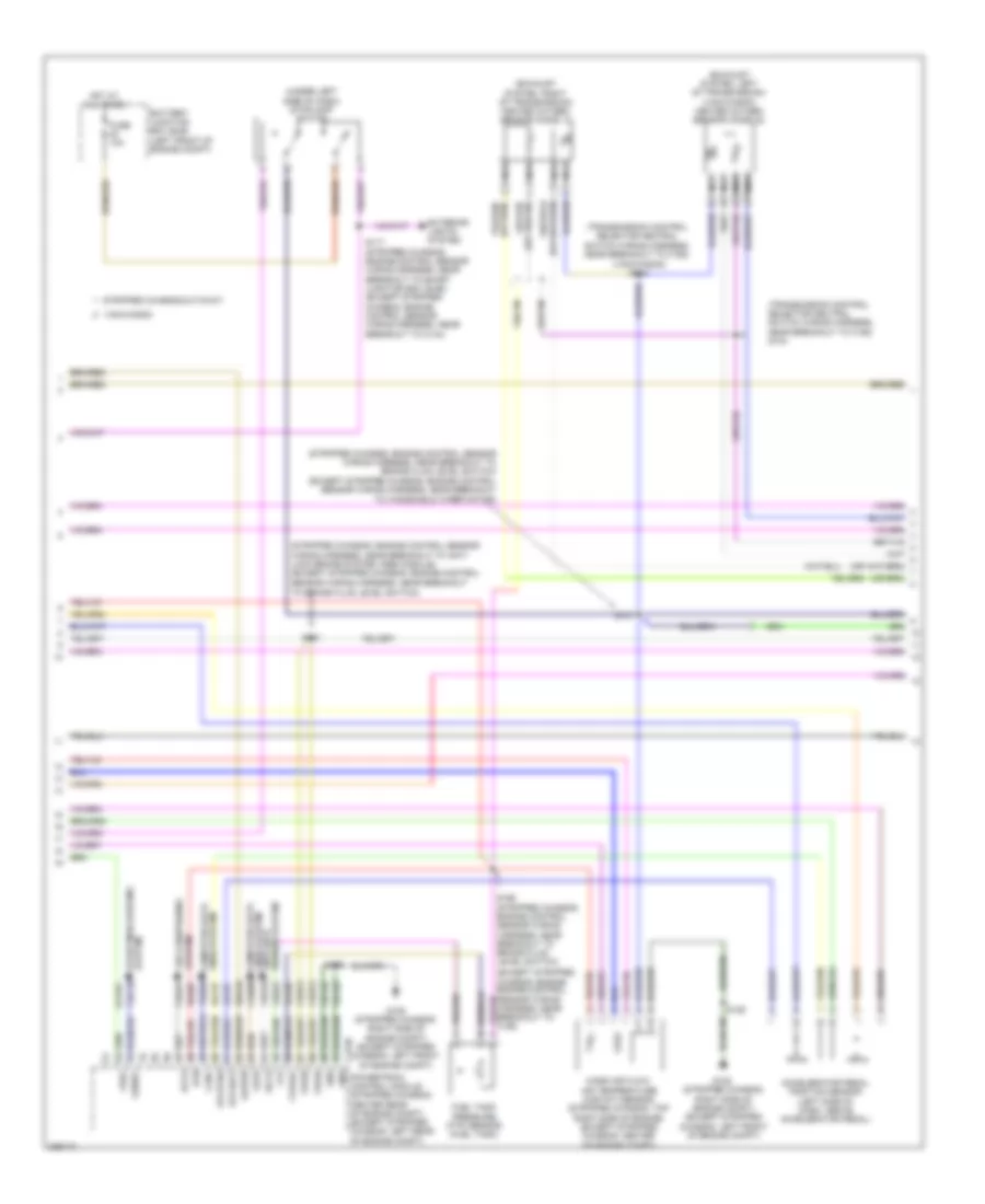
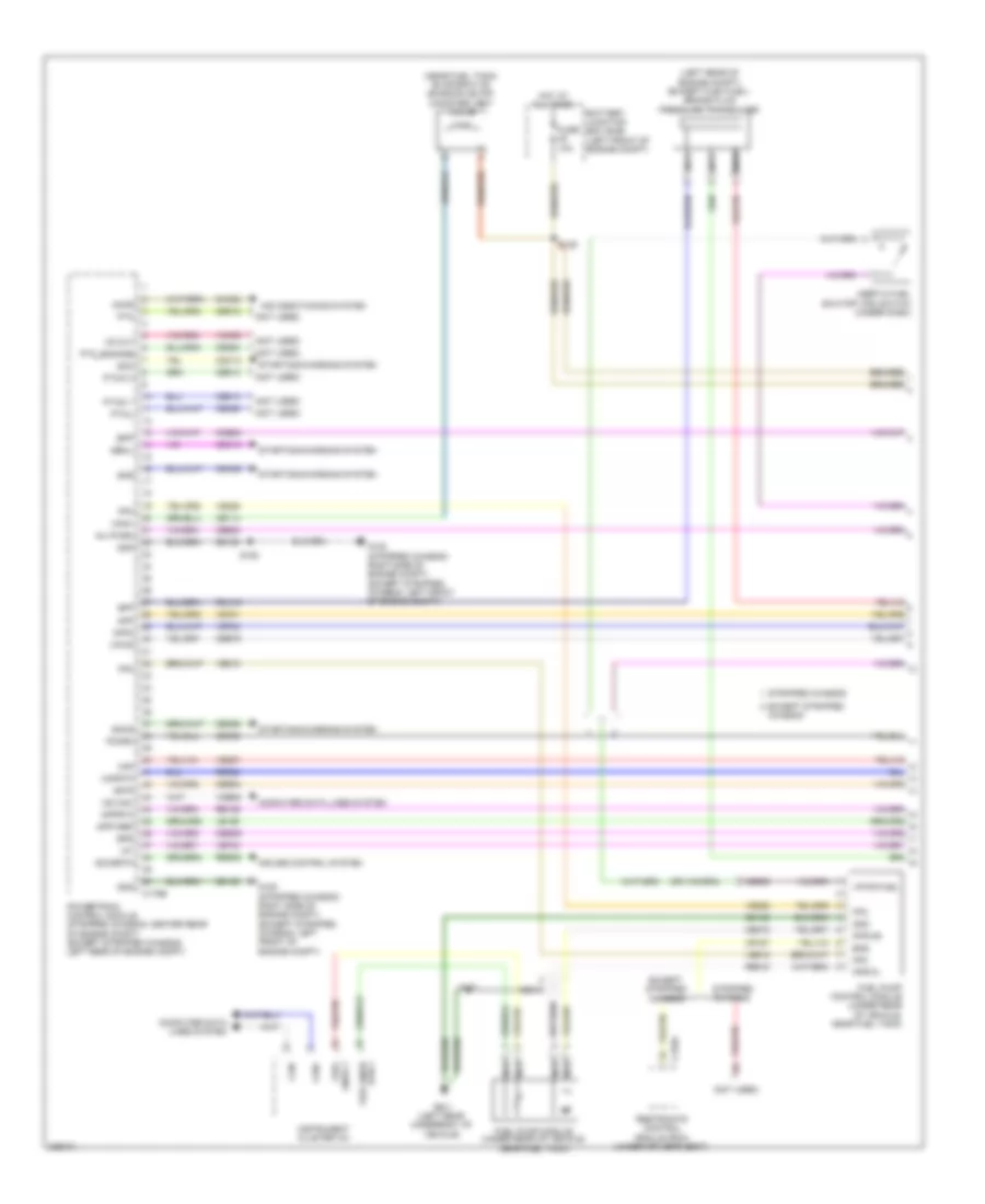
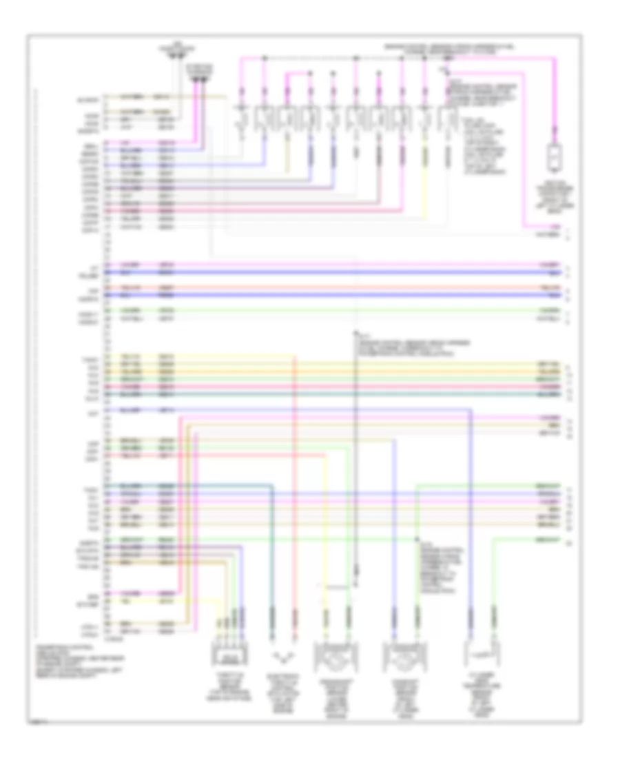
5.4L, Engine Performance Wiring Diagram, with Torqshift (1 of 5) for Ford Cutaway E250 2010

List of elements for 5.4L, Engine Performance Wiring Diagram, with Torqshift (1 of 5) for Ford Cutaway E250 2010:
- (left rear of engine compt) (except flex fuel) brake fluid pressure transducer
- (near fuel tank) evaporative emission (evap) canister vent valve
- (not used)
- Accr
- Air conditioning system
- App
- App2
- Apprtn
- Appvref
- Battery junction box (bjb) (left front of engine compt)
- Bfp
- Bpp
- Bps
- C175b
- C310a
- Can+
- Can-
- Canv
- Cbb54
- Cbb75
- Ccb08
- Cdc12
- Cdc15
- Cdc35
- Ce114
- Ce302
- Ce326
- Ce336
- Ce515
- Ce608
- Ce912
- Ce913
- Ce914
- Ce924
- Ces09
- Ch302
- Computer data lines system
- Cr167
- Cruise control system
- Ens
- Except stripped chassis
- Fpc
- Fpm
- Fppwr
- Fprtn
- Fuel pump driver module (under rear of vehicle, near fuel tank)
- Fuel pump module (under rear of vehicle, near fuel tank)
- Fuel sndr 1
- Fuel sndr rtn
- Fuse 10a
- G105 (stripped chassis: right side of engine compt) (except stripped chassis: left front of engine compt)
- G401 (left rear underbody of vehicle)
- Gd120
- Gd128
- Genli
- Gnd
- Hot at all times
- Hs can-
- Iat
- Inertia fuel shutoff (ifs) switch (under dash)
- Inj pwrm
- Instrument cluster (ic)
- Isp-r
- Le136
- Maf
- Mafrtn
- Nca
- Pcmrc
- Powertrain control module (stripped chassis: center rear of engine compt) (except stripped chassis: left rear of engine compt)
- Ptioc 1
- Pto
- Ptoengage
- Ptoic 2
- Ptoil
- Rca16
- Re136
- Re320
- Re515
- Res08
- Restraints control module (rcm) (under driver's seat)
- S125
- S129
- S407
- Sccsrtn
- Smc
- Smcs
- Smr
- Starting/charging system
- Stripped chassis
- Vdb05
- Ve225
- Ve518
- Ve701
- Ve702
- Ve740
- Ve807
- Vmc05
- Vpwr
- Vpwr fuel
- Vs out
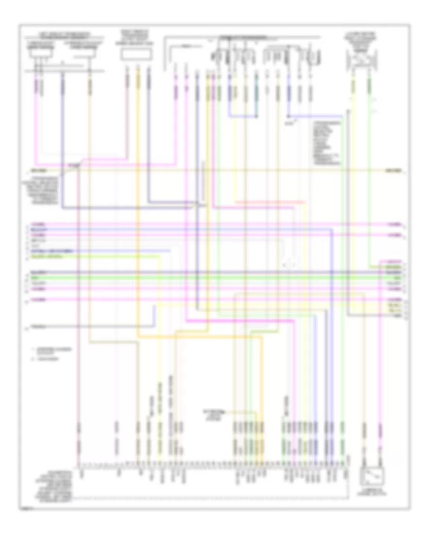
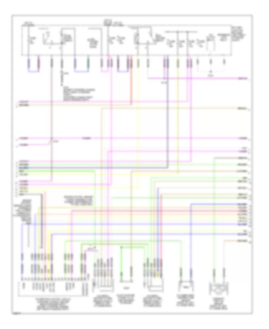
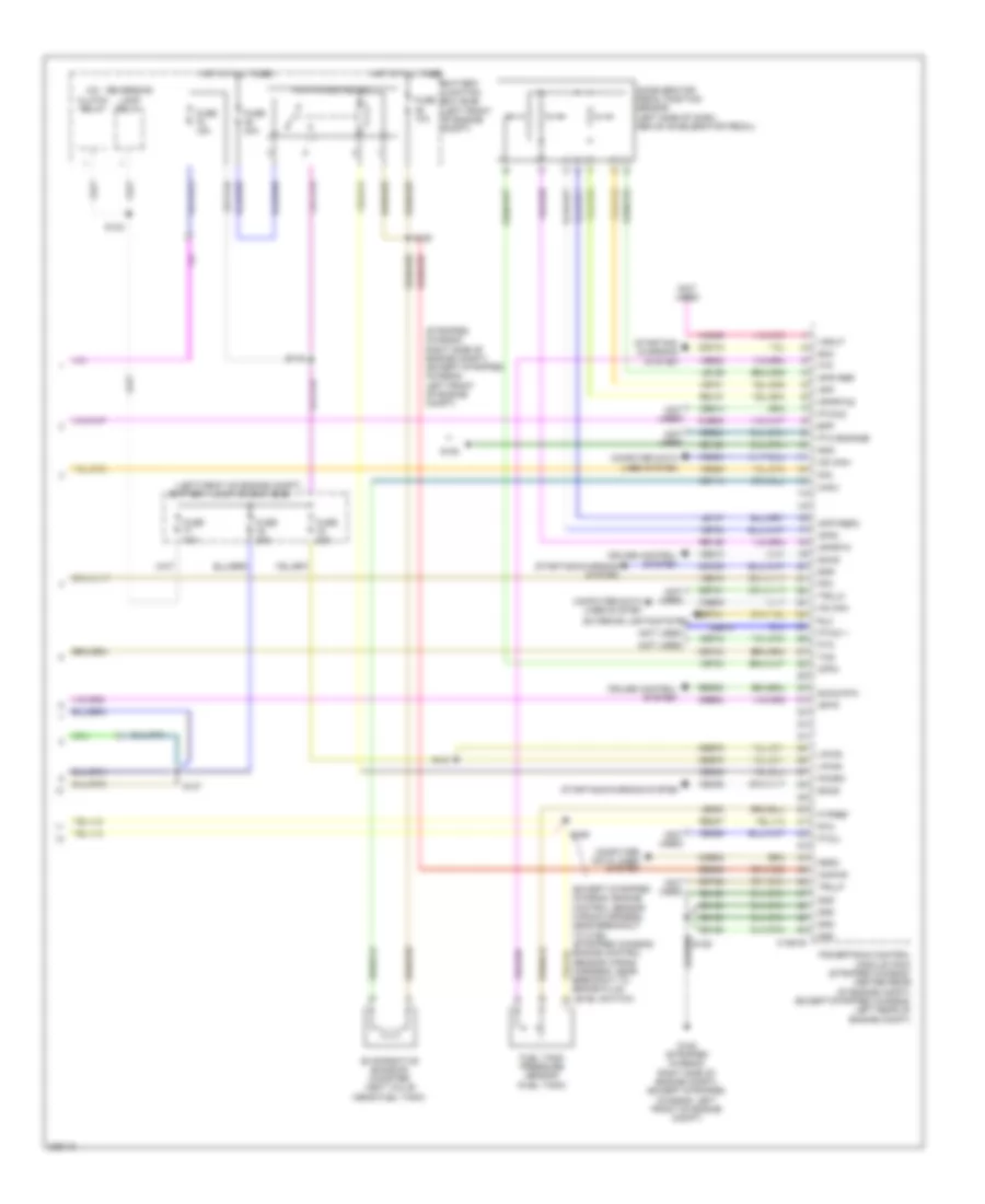
5.4L, Engine Performance Wiring Diagram, with Torqshift (2 of 5) for Ford Cutaway E250 2010
List of elements for 5.4L, Engine Performance Wiring Diagram, with Torqshift (2 of 5) for Ford Cutaway E250 2010:
- (except stripped
- (exhaust system, left of transmission) (van/wagon) heated oxygen sensor (ho2s) 22
- (exhaust system, right of transmission) heated oxygen sensor (ho2s) 12
- (stripped chassis: engine control sensor wiring harness, near breakout to anti- lock brake system (abs) module) (except stripped chassis: engine control
- (stripped chassis: engine control sensor wiring harness, near breakout to brake fluid level switch) (except stripped chassis: engine control
- (transmission control selector neutral switch wiring harness, near breakout to c192)
- (transmission control selector neutral switch wiring harness, near breakout to c192) s104
- (under left side of dash) stoplamp switch
- (van/wagon) s103
- Accelerator pedal position sensor (left side of dash, above accelerator pedal)
- Accs
- Anti-lock brakes system
- Battery junction box (bjb) (left front of engine compt)
- C175b
- Can+
- Cbb75
- Cdb08
- Cdc10
- Ch421
- Etcref3
- Etcrtn3
- Exterior lights system
- Feps
- Ftp
- Ftpref
- Fuel tank pressure (ftp) sensor (fuel tank)
- Fuse 10a
- G105 (stripped chassis: right side of engine compt) (except stripped chassis: left front of engine compt)
- Gd120
- Genrc
- Gnd
- Hot at all times
- Kapwr
- Lca16
- Le137
- Le230
- Lines system computer data
- Mass air flow/ air temperature (maf/iat) sensor (stripped chassis: top right side of engine) (except stripped chassis: center of engine compt)
- Nca
- Powertrain control module (stripped chassis: center rear of engine compt) (except stripped chassis: left rear of engine compt)
- Re137
- Re407
- Rtn
- S117 (stripped chassis: engine control sensor wiring harness, near breakout to smart junction box (sjb)) (except stripped chassis: engine control sensor wiring harness, near breakout to c144)
- S125
- S131
- S137
- S156 (stripped chassis: engine control sensor wiring harness, near breakout to brake fluid level switch)
- Sbb46
- Sccs
- Sensor wiring harness, near breakout to brake fluid level switch)
- Sensor wiring harness, near breakout to windshield wiper motor)
- Stripped chassis/cutaway
- System air conditioning
- System starting/charging
- Van/wagon
- Vdb04
- Ve922
- Ves10
- Vpwr
- Vref
5.4L, Engine Performance Wiring Diagram, with Torqshift (3 of 5) for Ford Cutaway E250 2010
List of elements for 5.4L, Engine Performance Wiring Diagram, with Torqshift (3 of 5) for Ford Cutaway E250 2010:
- (left side of transmission) speed sensor assembly
- (lower center front of engine) crankshaft position sensor
- (not used)
- (or ce239)
- (or ve745)
- (right rear of transmission) output shaft speed sensor (oss)
- (stripped chassis: center rear of engine compt) (except stripped chassis: left rear of engine compt)
- (transmission control selector neutral switch wiring harness, near breakout to torqshift transmission)
- C175t
- Ce223
- Ce234
- Cet05
- Cet06
- Cet07
- Cet08
- Cet09
- Cet21
- Cet22
- Cet25
- Cet34
- Cet41
- Cet50
- Cet51
- Cutaway
- Exterior
- Ho2s-12
- Ho2s-22
- Htr-12
- Htr-22
- Intermediate shaft speed sensor
- Iss
- Le111
- Lights system
- Nca
- Od cncl
- Oss
- Overdrive cancel switch
- Pc-a
- Powertrain control module
- Re406
- Ret04
- Ret24
- Rlc
- S100
- S101
- S102
- Sigrtn
- Sspc a
- Sspc b
- Sspc c
- Sspc d
- Sspc e
- Sspc-a
- Sspc-b
- Sspc-c
- Sspc-d
- Sspc-e
- Stripped chassis/
- Tcc
- Tft
- Torqshift transmission
- Tr gnd
- Tr-p
- Tro_n
- Tro_p
- Tspc
- Tss
- Turbine shaft speed sensor
- Van/wagon
- Ve731
- Ve733
- Ve744
- Vet27
- Vet32
- Vet33
- Vref
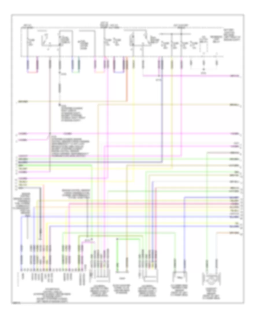
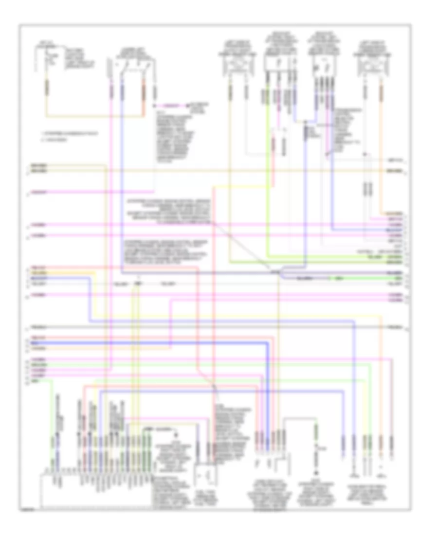
5.4L, Engine Performance Wiring Diagram, with Torqshift (4 of 5) for Ford Cutaway E250 2010
List of elements for 5.4L, Engine Performance Wiring Diagram, with Torqshift (4 of 5) for Ford Cutaway E250 2010:
- (engine control sensor wiring harness & fuel charge, in breakout to crankshaft position sensor) s178
- (engine control sensor wiring harness & fuel charge, near breakout to fuel injector 8)
- A/c clutch relay
- Battery junction box (bjb) (left front of engine compt)
- C175e
- Camshaft position sensor (front of left cylinder head)
- Ce235
- Ce236
- Ce303
- Ce304
- Ce305
- Ce308
- Ce309
- Ce426
- Ckp+
- Cop1a
- Cop2d
- Cop3b
- Cop6e
- Cop7c
- Cylinder head temperature sensor (front of left cylinder head)
- De135
- Etc ref
- Etc rtn
- Evap canister purge valve (center rear of engine)
- Fuel power motor diode
- Fuel pump relay
- Fuse 10a
- Fuse 20a
- Fuse 40a
- G100 (stripped chassis: right side of of engine compt) (except stripped chassis: right front of engine compt)
- Hot at all times
- Hot in run or start
- Hot in start or run
- Le134
- Nca
- Pcm power relay
- Powertrain control module (stripped chassis: center rear of engine compt) (except stripped chassis: left rear of engine compt)
- Re134
- Re405
- Red
- Reversing lamp relay
- S108
- S116
- S124
- S130 (stripped chassis: engine control sensor wiring harness, near breakout to anti-lock brake system (abs) module) (except stripped chassis: engine control sensor wiring harness, near breakout to brake fluid level switch)
- S174
- Shdrtn
- Sigrtn
- Tacm-
- Universal heated oxygen sensor (ho2s) 11 (rear of right cylinder bank)
- Universal heated oxygen sensor (ho2s) 21 (rear of left cylinder bank)
- Uo2shtr11
- Uo2shtr21
- Ve711
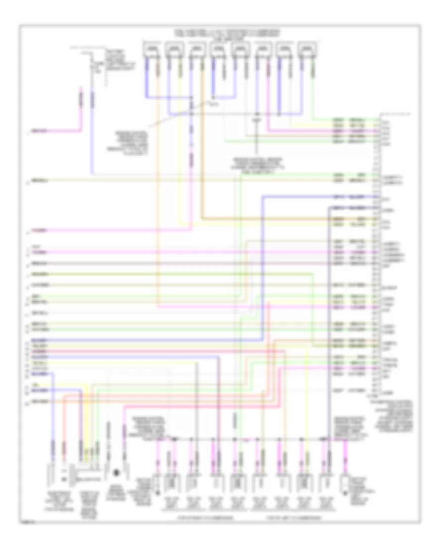
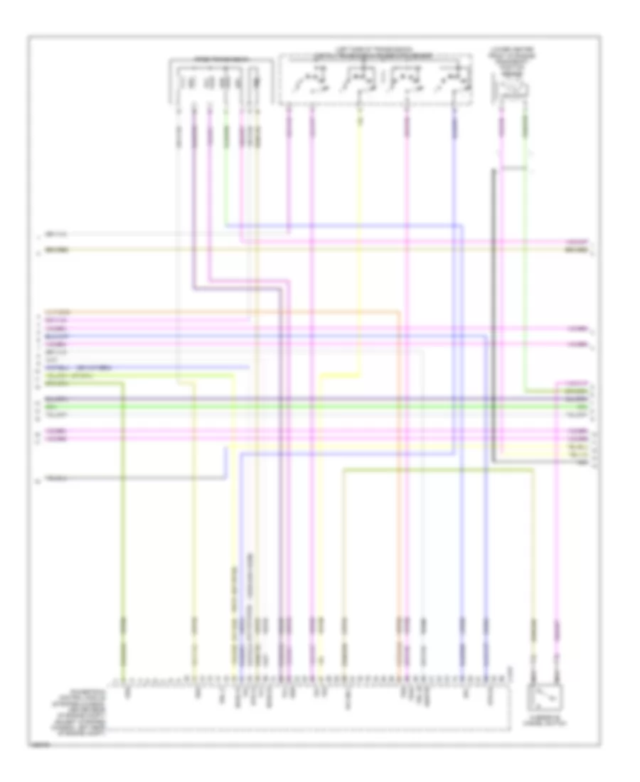
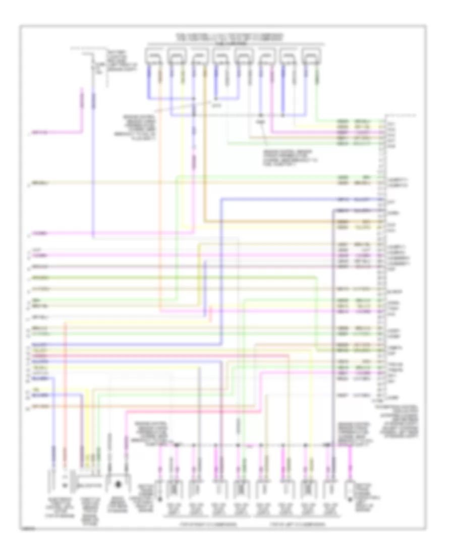
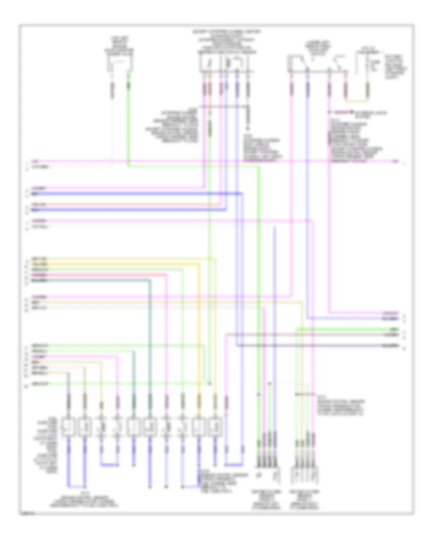
5.4L, Engine Performance Wiring Diagram, with Torqshift (5 of 5) for Ford Cutaway E250 2010
List of elements for 5.4L, Engine Performance Wiring Diagram, with Torqshift (5 of 5) for Ford Cutaway E250 2010:
- (engine control sensor wiring harness & fuel charge, near breakout to coil on
- (engine control sensor wiring harness & fuel charge, near breakout to coil on plug (cop) 7)
- (engine control sensor wiring harness & fuel charge, near breakout to fuel injector 1)
- (engine control sensor wiring harness & fuel charge, near breakout to fuel injector 2)
- (fuel injectors 1, 2, 3 & 4: top of right cylinder bank) (fuel injectors 5, 6, 7 & 8: top of left cylinder bank) fuel injectors
- (top of left cylinder bank)
- (top of right cylinder bank)
- Battery junction box (bjb) (left front of engine compt)
- C175e
- Ce113
- Ce205
- Ce206
- Ce207
- Ce208
- Ce209
- Ce210
- Ce211
- Ce212
- Ce306
- Ce307
- Ce310
- Ce412
- Cht
- Ckp-
- Cmp
- Coil on plug (cop) 1
- Coil on plug (cop) 2
- Coil on plug (cop) 3
- Coil on plug (cop) 4
- Coil on plug (cop) 5
- Coil on plug (cop) 6
- Coil on plug (cop) 7
- Coil on plug (cop) 8
- Cop4g
- Cop5f
- Cop8h
- Electronic throttle control (etc) motor (top of engine)
- Evapcp
- Fuse 15a
- Ignition trans- former capacitor 1 (top right front of engine)
- Ignition trans- former capacitor 2 (left front of engine)
- Inj1
- Inj2
- Inj3
- Inj4
- Inj5
- Inj6
- Inj7
- Inj8
- Knock sensor (top rear of engine)
- Ks1+
- Ks1-
- Le448
- Le449
- Le450
- Le451
- Le452
- Le453
- Nca
- Plug (cop) 7)
- Powertrain control module (pcm) (stripped chassis: center rear of engine compt) (except stripped chassis: left rear of engine compt)
- Re135
- Re323
- Re429
- S170
- S173
- S175
- S177
- Solid state
- Tacm+
- Throttle position sensor (top of engine, near air intake)
- Tps1-ns
- Tps2-ps
- Uo2s11
- Uo2s21
- Uo2sgref11
- Uo2sgref21
- Uo2spc11
- Uo2spct11
- Uo2spct21
- Uo2sps21
- Ve707
- Ve712
- Ve801
- Ve818
- Ve819
- Ve826
- Ve827
- Vrsrtn
5.4L, Engine Performance Wiring Diagram, without Torqshift (1 of 5) for Ford Cutaway E250 2010
List of elements for 5.4L, Engine Performance Wiring Diagram, without Torqshift (1 of 5) for Ford Cutaway E250 2010:
- (left rear of engine compt) (except flex fuel) brake fluid pressure transducer
- (near fuel tank) evaporative emission (evap) canister vent valve
- (not used)
- Accr
- Air conditioning system
- App
- App2
- Apprtn
- Appvref
- Battery junction box (bjb) (left front of engine compt)
- Bfp
- Bpp
- Bps
- C175b
- C310a
- Can+
- Can-
- Canv
- Cbb54
- Cbb75
- Ccb08
- Cdc12
- Cdc15
- Cdc35
- Ce114
- Ce302
- Ce326
- Ce336
- Ce515
- Ce608
- Ce912
- Ce913
- Ce914
- Ce924
- Ces09
- Ch302
- Computer data lines system
- Cr167
- Cruise control system
- Ens
- Except stripped chassis
- Fpc
- Fpm
- Fppwr
- Fprtn
- Fuel
- Fuel pump control module (under rear of vehicle, near fuel tank)
- Fuel pump module (under rear of vehicle, near fuel tank)
- Fuel sndr rtn 1
- Fuse 10a
- G105 (stripped chassis: right side of engine compt) (except stripped chassis: left front of engine compt)
- G401 (left rear underbody of vehicle)
- Gd120
- Gd128
- Genli
- Gnd
- Hot at all times
- Hs can-
- Iat
- Inertia fuel shutoff (ifs) switch (under dash)
- Inj pwrm
- Instrument cluster (ic)
- Isp-r
- Le136
- Maf
- Mafrtn
- Nca
- Pcmrc
- Powertrain control module (stripped chassis: center rear of engine compt) (except stripped chassis: left rear of engine compt)
- Ptioc 1
- Pto
- Ptoic 2
- Ptoil
- Pto_engage
- Rca16
- Re136
- Re320
- Re515
- Res08
- Restraints control module (rcm) (under driver's seat)
- S125
- S129
- S407
- Sccsrtn
- Smc
- Smcs
- Smr
- Sndr 1
- Starting/charging system
- Stripped chassis
- Vdb05
- Ve225
- Ve518
- Ve701
- Ve702
- Ve740
- Ve807
- Vmc05
- Vpwr
- Vpwr fuel
- Vs out
5.4L, Engine Performance Wiring Diagram, without Torqshift (2 of 5) for Ford Cutaway E250 2010
List of elements for 5.4L, Engine Performance Wiring Diagram, without Torqshift (2 of 5) for Ford Cutaway E250 2010:
- (except stripped
- (exhaust system, left of transmission) (van/wagon) heated oxygen sensor (ho2s) 22
- (exhaust system, right of transmission) (van/wagon)
- (left side of transmission) output shaft speed sensor (oss)
- (left side of transmission) turbine shaft speed sensor (oss)
- (stripped chassis: engine control sensor wiring harness, near breakout to anti- lock brake system (abs) module) (except stripped chassis: engine control
- (stripped chassis: engine control sensor wiring harness, near breakout to brake fluid level switch) (except stripped chassis: engine control
- (stripped chassis: right side of engine compt) (except stripped chassis: left front of engine compt)
- (transmission control selector neutral switch wiring harness, near breakout to c192) s104
- (under left side of dash) stoplamp switch
- Accelerator pedal position sensor (left side of dash, above accelerator pedal)
- Accs
- Anti-lock brakes system
- Battery junction box (bjb) (left front of engine compt)
- C175b
- Can+
- Cbb75
- Cdb08
- Cdc10
- Ch421
- Chassis: engine engine control sensor wiring harness, near breakout to c192)
- Etcref3
- Etcrtn3
- Exterior lights system
- Feps
- Ftp
- Ftpref
- Fuel tank pressure (ftp) sensor (fuel tank)
- Fuse 10a
- G105
- G105 (stripped chassis: right side of engine compt) (except stripped chassis: left front of engine compt)
- Gd120
- Genrc
- Gnd
- Gnd powertrain control module (stripped chassis: center rear of engine compt) (except stripped chassis: left rear of engine compt)
- Heated oxygen sensor (ho2s) 12
- Hot at all times
- Kapwr
- Lca16
- Le137
- Le230
- Lines system computer data
- Mass air flow/ air temperature (maf/iat) sensor (stripped chassis: top right side of engine) (except stripped chassis: center of engine compt)
- Nca
- Re137
- Re407
- Rtn
- S117 (stripped chassis: engine control sensor wiring harness, near breakout to smart junction box (sjb)) (except stripped chassis: engine control sensor wiring harness, near breakout to c144)
- S125
- S131
- S137
- S156 (stripped chassis: engine control sensor wiring harness, near breakout to brake fluid level switch)
- Sbb46
- Sccs
- Sensor wiring harness, near breakout to brake fluid level switch)
- Sensor wiring harness, near breakout to windshield wiper motor)
- Stripped chassis/cutaway
- System air conditioning
- System starting/charging
- Van/wagon
- Vdb04
- Ve922
- Ves10
- Vpwr
- Vref
5.4L, Engine Performance Wiring Diagram, without Torqshift (3 of 5) for Ford Cutaway E250 2010
List of elements for 5.4L, Engine Performance Wiring Diagram, without Torqshift (3 of 5) for Ford Cutaway E250 2010:
- (left side of transmission) digital transmission range (dtr) sensor
- (lower center front of engine) crankshaft position sensor
- (or ce239)
- (or ve745)
- (stripped chassis: center rear of engine compt) (except stripped chassis: left rear of engine compt)
- 4r75e transmission
- C175t
- Ce223
- Ce234
- Ce418
- Cet05
- Cet18
- Cet19
- Cet34
- Epc
- Ho2s-12
- Ho2s-22
- Htr-12
- Htr-22
- N r
- Nca
- Od cncl
- Oss
- Overdrive cancel switch
- Powertrain control module
- Re406
- Sigrtn
- Ssa
- Ssb
- Tcc
- Tft
- Tr1
- Tr2
- Tr3a
- Tr4
- Tro_n
- Tro_p
- Tss
- Ve731
- Ve733
- Vet26
- Vet27
- Vet28
- Vet29
- Vet30
- Vet31
- Vet33
5.4L, Engine Performance Wiring Diagram, without Torqshift (4 of 5) for Ford Cutaway E250 2010
List of elements for 5.4L, Engine Performance Wiring Diagram, without Torqshift (4 of 5) for Ford Cutaway E250 2010:
- (engine control sensor wiring harness & fuel charge, in breakout to crankshaft position sensor) s178
- (engine control sensor wiring harness & fuel charge, near breakout to fuel injector 8)
- A/c clutch relay
- Battery junction box (bjb) (left front of engine compt)
- C175e
- Camshaft position sensor (front of left cylinder head)
- Cd6e
- Ce235
- Ce236
- Ce303
- Ce304
- Ce305
- Ce308
- Ce309
- Ce426
- Ckp+
- Cop1a
- Cop2d
- Cop3b
- Cop7c
- Cylinder head temperature sensor (front of left cylinder head)
- De135
- Etc ref
- Etc rtn
- Evap canister purge valve (center rear of engine)
- Fuel power motor diode
- Fuel pump relay
- Fuse 10a
- Fuse 20a
- Fuse 40a
- G100 (except stripped chassis: right front of engine compt) (stripped chassis: right side of engine compt)
- Hot at all times
- Hot in run or start
- Le134
- Pcm power relay
- Powertrain control module (stripped chassis: center rear of engine compt) (except stripped chassis: left rear of engine compt)
- Re134
- Re405
- Red
- Reversing lamp relay
- S108
- S116
- S124
- S130
- S174
- Shdrtn
- Sigrtn
- Tacm-
- Universal heated oxygen sensor (ho2s) 11 (rear of right cylinder bank)
- Universal heated oxygen sensor (ho2s) 21 (rear of left cylinder bank)
- Uo2shtr11
- Uo2shtr21
- Ve711
5.4L, Engine Performance Wiring Diagram, without Torqshift (5 of 5) for Ford Cutaway E250 2010
List of elements for 5.4L, Engine Performance Wiring Diagram, without Torqshift (5 of 5) for Ford Cutaway E250 2010:
- (engine control sensor wiring harness & fuel charge, near breakout to coil on
- (engine control sensor wiring harness & fuel charge, near breakout to coil on plug (cop) 7)
- (engine control sensor wiring harness & fuel charge, near breakout to fuel injector 1)
- (engine control sensor wiring harness & fuel charge, near breakout to fuel injector 2)
- (fuel injectors 1, 2, 3 & 4: top of right cylinder bank) (fuel injectors 5, 6, 7 & 8: top of left cylinder bank) fuel injectors
- (top of left cylinder bank)
- (top of right cylinder bank)
- Battery junction box (bjb) (left front of engine compt)
- C175e
- Ce113
- Ce205
- Ce206
- Ce207
- Ce208
- Ce209
- Ce210
- Ce211
- Ce212
- Ce306
- Ce307
- Ce310
- Ce412
- Cht
- Ckp-
- Cmp
- Coil on plug (cop) 1
- Coil on plug (cop) 2
- Coil on plug (cop) 3
- Coil on plug (cop) 4
- Coil on plug (cop) 5
- Coil on plug (cop) 6
- Coil on plug (cop) 7
- Coil on plug (cop) 8
- Cop4g
- Cop5f
- Cop8h
- Electronic throttle control (etc) motor (top of engine)
- Evapcp
- Fuse 15a
- Ignition trans- former capacitor 1 (top right front of engine)
- Ignition trans- former capacitor 2 (left front of engine)
- Inj1
- Inj2
- Inj3
- Inj4
- Inj5
- Inj6
- Inj7
- Inj8
- Knock sensor (top rear of engine)
- Ks1+
- Ks1-
- Le448
- Le449
- Le450
- Le451
- Le452
- Le453
- Nca
- Plug (cop) 7)
- Powertrain control module (pcm) (stripped chassis: center rear of engine compt) (except stripped chassis: left rear of engine compt)
- Re135
- Re323
- Re429
- S170
- S173
- S175
- S177
- Solid state
- Tacm+
- Throttle position sensor (top of engine, near air intake)
- Tps1-ns
- Tps2-ps
- Uo2s11
- Uo2s21
- Uo2sgref11
- Uo2sgref21
- Uo2spc11
- Uo2spc21
- Uo2spct11
- Uo2spct21
- Ve707
- Ve712
- Ve801
- Ve818
- Ve819
- Ve826
- Ve827
- Vrsrtn
6.0L DIESEL
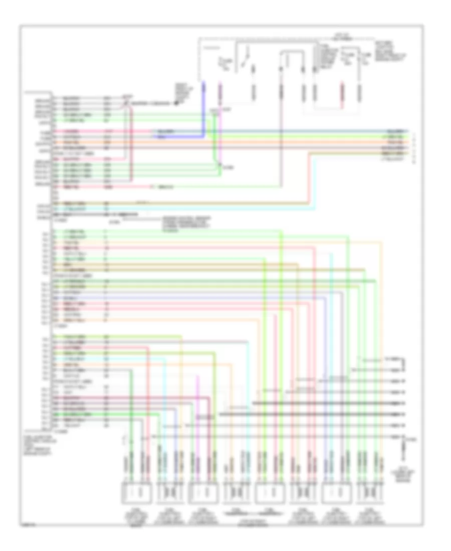
6.0L Diesel, Engine Performance Wiring Diagram (1 of 5) for Ford Cutaway E250 2010
List of elements for 6.0L Diesel, Engine Performance Wiring Diagram (1 of 5) for Ford Cutaway E250 2010:
- (engine control sensor wiring harness & fuel charge, near breakout to g108)
- (pins 11-21 not used)
- (pins 9-16 not used)
- (right front of engine compt) g106
- (top of right cylinder bank)
- Battery junction box (bjb) (right front of engine compt)
- C1388a
- C1388b
- C1388c
- Can 2h
- Ckp-o
- Cmp-o
- Fuel injector 1 (top of right cylinder bank)
- Fuel injector 2
- Fuel injector 3 (top of right cylinder bank)
- Fuel injector 4
- Fuel injector 5 (top of left cylinder bank)
- Fuel injector 6 (top of left cylinder bank)
- Fuel injector 7 (top of left cylinder bank)
- Fuel injector 8 (top of left cylinder bank)
- Fuel injector control module (ficm) (left rear of engine compt)
- Fuel injector control module power relay
- Fuse
- Fuse 10a
- Fuse 15a
- Fuse 50a
- G110 (lower left rear of engine)
- Ground
- Ground pcm rly
- Hot at all times
- Inj +
- Inj -
- Nca
- Pcm rly
- S1060
- S1061
- S1062
- S1063
- Shield
- Sig rtn
6.0L Diesel, Engine Performance Wiring Diagram (2 of 5) for Ford Cutaway E250 2010
List of elements for 6.0L Diesel, Engine Performance Wiring Diagram (2 of 5) for Ford Cutaway E250 2010:
- (engine control sensor wiring harness, near breakout to brake fluid level switch) s156
- (engine control sensor wiring harness, near breakout to windshield wiper motor)
- (left frame rail) fuel heater
- (not used)
- Accr
- Accs
- Acpsw
- Air conditioning system
- App
- App2
- App3
- Apprtn
- Appvref
- Baro
- Barometric absolute pressure (baro) sensor (left end of dash)
- Battery junction box (bjb) (right front of engine compt)
- Bcpsw
- Bpp
- Brk press sw
- C1381b
- Can+
- Can-
- Cbb55
- Cbb75
- Ccb08
- Cdb08
- Cdc09
- Cdc12
- Ce302
- Ce912
- Ce913
- Ce914
- Ce926
- Cet22
- Cet34
- Ch302
- Ch419
- Ch425
- Charging ind
- Cmc22
- Cmc25
- Computer data lines system
- Cruise control system
- Customer access
- Exterior lights system
- Feps
- Fpc
- Fpm
- Fuse 10a
- Fuse 15a
- Fuse 20a
- Fuse 40a
- G105 (left side of engine compt)
- G401 (left rear underbody of vehicle)
- Gd120
- Gnd
- Hot at all times
- Hot in start or run
- Iat
- Isp-r
- Kapwr
- Le136
- Le329
- Le423
- Le434
- Maf
- Mafrtn
- Manifold absolute pressure (map) sensor (right side of engine compt)
- Map
- Mass air flow/intake air temperature (maf/iat) sensor (left rear of engine compt)
- Nca
- Od cncl
- Overdrive cancel switch
- Park brake
- Pcm power relay
- Pcmrc
- Powertrain control module (pcm) (left rear of engine compt)
- Pto
- Pto ground
- Pto vref
- Ptoic 1
- Ptoic 2
- Re136
- Re320
- Re327
- Re407
- Red
- Res08
- S116
- S117
- S125
- S154
- Sbb46
- Sccs
- Sccs rtn
- Sig trn cowl
- Smr
- Starting/charging system
- Starting/charging system cruise control system
- Tr0-p
- Vdb04
- Vdb05
- Ve225
- Ve518
- Ve701
- Ve702
- Ve703
- Ve705
- Ve740
- Ve807
- Ve823
- Ves10
- Vmc05
- Vpwra
- Vpwrb
- Vref
- Vsout
- Water in fuel sensor (left frame rail)
- Wif
6.0L Diesel, Engine Performance Wiring Diagram (3 of 5) for Ford Cutaway E250 2010
List of elements for 6.0L Diesel, Engine Performance Wiring Diagram (3 of 5) for Ford Cutaway E250 2010:
- (engine control sensor wiring harness, near breakout to windshield wiper motor) s160
- (near left kick panel) parking brake switch
- Accelerator pedal position sensor (left side of dash, above accelerator pedal)
- Battery junction box (bjb) (right front of engine compt)
- Brake pressure switch (left rear of engine compt)
- Camshaft position sensor (front of left cylinder head)
- Crankshaft position sensor (lower center front of engine)
- Fuel pump (left frame rail)
- Fuel pump motor diode
- Fuel pump relay
- Fuse 10a
- Fuse 20a
- G203 (left kick panel)
- G401 (left rear underbody of vehicle)
- Hot at all times
- Inertia fuel shutoff switch (right kick panel)
- Instrument cluster system
- Nca
- Red
- S1064 (engine control sensor wiring harness & fuel charge, near breakout to powertrain control module (pcm))
- S239
- Stoplamp switch (under left side of dash)
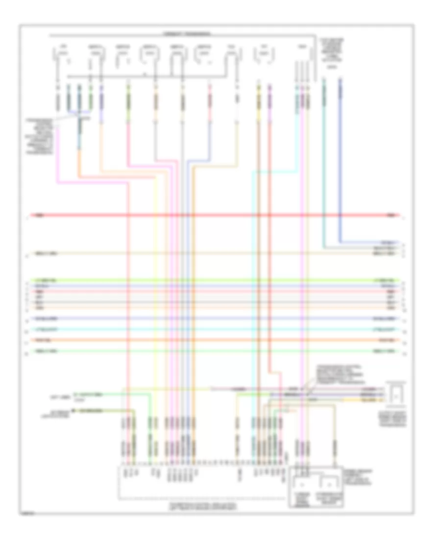
6.0L Diesel, Engine Performance Wiring Diagram (4 of 5) for Ford Cutaway E250 2010
List of elements for 6.0L Diesel, Engine Performance Wiring Diagram (4 of 5) for Ford Cutaway E250 2010:
- (not used)
- (top center of engine) variable geometric turbo actuator
- (transmission control selector neutral switch wiring harness, in breakout to torqshift transmission)
- (transmission control selector neutral switch wiring harness, near breakout to torqshift transmission)
- C1047
- C1381t
- Cet05
- Cet20
- Cet25
- Cet41
- Cet50
- Cet51
- Ceto6
- Ceto7
- Ceto8
- Ceto9
- Exterior lights system
- Intermediate shaft speed sensor
- Iss
- Le111
- Lpc
- Oss
- Output shaft speed sensor (right side of transmission)
- Pc-a
- Powertrain control module (pcm) (left rear of engine compartment)
- Re406
- Red
- Ret04
- Ret24
- Rlc
- S100
- S101
- S102
- Sig trn
- Speed sensor assembly (left side of transmission)
- Sppc-a
- Sppc-d
- Sspc-a
- Sspc-b
- Sspc-c
- Sspc-d
- Sspc-e
- Tcc
- Tcil
- Tft
- Torqshift transmission
- Tr gnd
- Tr-p
- Tspc
- Tss
- Turbine shaft speed sensor
- Ve744
- Vet27
- Vet32
- Vet33
- Vref
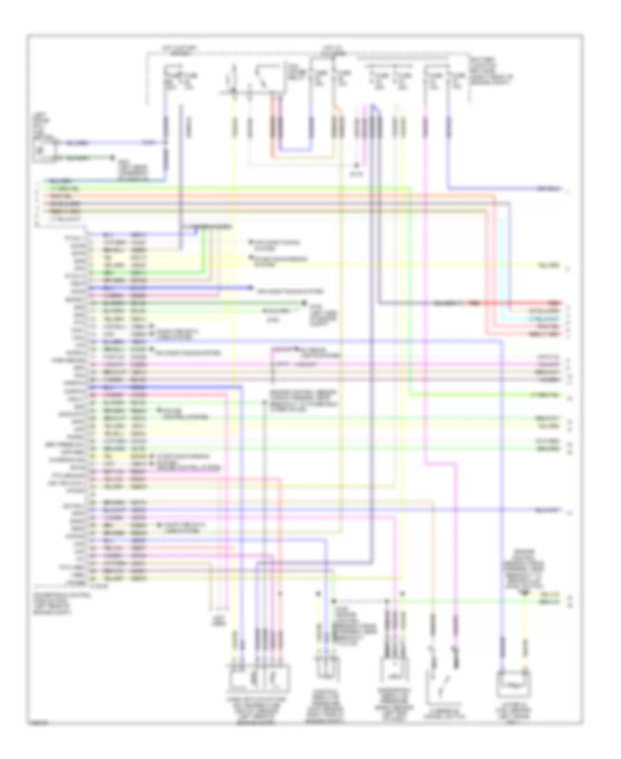
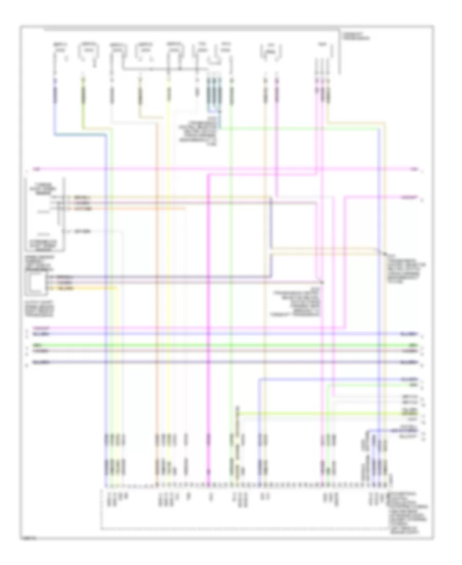
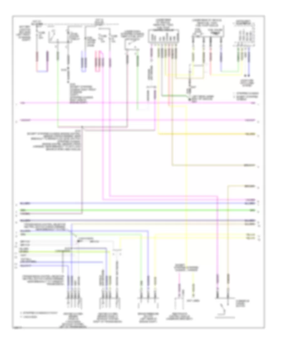
6.0L Diesel, Engine Performance Wiring Diagram (5 of 5) for Ford Cutaway E250 2010
List of elements for 6.0L Diesel, Engine Performance Wiring Diagram (5 of 5) for Ford Cutaway E250 2010:
- (center rear of engine) injection pressure regulator (ipr)
- (engine control sensor wiring harness & fuel charge, near breakout to intake air temperature 2 (iat2) sensor)
- (top front of engine) electronic fan clutch
- (top left rear of engine) glow plug control module
- (top of left cylinder bank) left glow plug bank
- (top of right cylinder bank) right glow plug bank
- Bcpil
- C1273a
- C1273b
- C1381e
- Can 2h
- Ckp -
- Ckp+
- Ckp-o
- Cmp -
- Cmp+
- Cmp-o
- Cntl
- Cooling fans system
- Customer access
- Ebp
- Ect
- Egr
- Egr valve actuator (top center front of engine)
- Egrmc
- Engine coolant temperature (ect) sensor (upper front of engine)
- Engine oil temperature (eot) sensor (top center of engine)
- Eot
- Exhaust back pressure (ebp) sensor (top left of engine)
- Fss
- G301 (near secondary battery)
- Gen_mon
- Glow plug 1
- Glow plug 2
- Glow plug 3
- Glow plug 4
- Glow plug 5
- Glow plug 6
- Glow plug 7
- Glow plug 8
- Gpd
- Gpe
- Iat2
- Icp
- Injection control pressure (icp) sensor (top right front of engine)
- Intake air temperature 2 (iat2) sensor (top left side of engine)
- Ipr
- Nca
- Power distribution system
- Powertrain control module (pcm) (left rear of engine compt)
- Primary battery
- Ptoc
- Red
- S1051
- S1052
- S1054
- S1057 (engine control sensor wiring harness & fuel charge, near breakout to evap canister purge valve)
- S1058
- S1059
- S1071
- S1072
- Secondary battery
- Shield
- Sig rtn
- Signal
- Signal return
- Starter motor
- Starting/charging system
- Vgt
- Vgtch
- Vpwr
- Vref
6.8L
6.8L, Engine Performance Wiring Diagram (1 of 5) for Ford Cutaway E250 2010
List of elements for 6.8L, Engine Performance Wiring Diagram (1 of 5) for Ford Cutaway E250 2010:
- (engine control sensor wiring harness & fuel charge, near breakout to c1046)
- Accr
- Accs
- Air conditioning system
- Bps
- C1551e
- Camshaft position sensor (front of left cylinder head)
- Cbk01
- Cdc10
- Cdc15
- Ce113
- Ce205
- Ce206
- Ce207
- Ce208
- Ce209
- Ce210
- Ce211
- Ce212
- Ce213
- Ce214
- Ce235
- Ce236
- Ce303
- Ce304
- Ce305
- Ce306
- Ce307
- Ce308
- Ce309
- Ce310
- Ce311
- Ce312
- Ce412
- Ce426
- Ces09
- Ch302
- Cht
- Ckp+
- Ckp-
- Cmp
- Coil on plugs (cop) (coil on plugs 1, 2, 3, 4 & 5: top of right cylinder bank) (coil on plugs 6, 7, 8, 9 & 10: top of left cylinder bank)
- Cop10d
- Cop1a
- Cop2e
- Cop3g
- Cop4i
- Cop5c
- Cop6b
- Cop7f
- Cop8h
- Cop9j
- Crankshaft position sensor (lower center front of engine)
- Cylinder head temperature sensor (front of left cylinder head)
- De135
- Electronic throttle control (etc) motor (top left side of engine)
- Etc ref
- Etc rtn
- Evapcp
- Genli
- Genrc
- Ho2s-11
- Ho2s-21
- Htr-11
- Htr-21
- Iat
- Ifs_ref
- Ignition transformer capacitor 1 (front of left cylinder bank)
- Inj1
- Inj10
- Inj2
- Inj3
- Inj4
- Inj5
- Inj6
- Inj7
- Inj8
- Inj9
- Le134
- Maf
- Mafrtn
- Nca
- Powertrain control module (pcm) (stripped chassis: center rear of engine compt) (except stripped chassis: left rear of engine compt)
- Re134
- Re135
- Re320
- Re405
- S170
- S171 (engine control sensor wiring harness & fuel charge, in breakout to powertrain control module (pcm))
- S172 (engine control sensor wiring harness & fuel charge, in breakout to powertrain control module (pcm))
- Shdrtn
- Sigrtn
- Solid state
- Starting/ charging system
- Tacm+
- Tacm-
- Throttle position sensor (top of engine, near air intake)
- To fuel injector 1.)
- Tps1-ns
- Tps2-ns
- Ve706
- Ve711
- Ve712
- Ve735
- Ve737
- Ve740
- Ve807
- Ve818
- Ve819
6.8L, Engine Performance Wiring Diagram (2 of 5) for Ford Cutaway E250 2010
List of elements for 6.8L, Engine Performance Wiring Diagram (2 of 5) for Ford Cutaway E250 2010:
- (engine control sensor wiring harness & fuel charge, near breakout to coil on plug (cop) 10)
- (except stripped chassis: center of engine compt) (stripped chassis: top right side of engine) mass air flow/intake air temperature (maf/iat) sensor
- (stripped chassis: engine control sensor harness, near breakout to g105) (except stripped chassis: engine control sensor wiring harness, near breakout to c192)
- (top left rear of engine) evap canister purge valve
- (under left side of dash) stoplamp switch
- Battery junction box (bjb) (left front of engine compt)
- Exterior lights system
- Fuel injectors (fuel injectors 1, 2, 3 ,4 & 5: top of right cylinder bank) (fuel injectors 6, 7, 8, 9 & 10: top of left cylinder bank)
- Fuse 10a
- G105 (stripped chassis: right side of engine compt) (except stripped chassis: left front of engine compt)
- Harness, near breakout to smart junction box (sjb)) (except stripped chassis: engine control sensor wiring harness, near breakout to c144)
- Heated oxygen sensor (ho2s) 11 (rear of right cylinder bank)
- Heated oxygen sensor (ho2s) 21 (rear of left cylinder bank)
- Hot at all times
- Nca
- S125
- S173 (engine control sensor wiring harness & fuel charge, near breakout to fuel injector 8)
- S174
6.8L, Engine Performance Wiring Diagram (3 of 5) for Ford Cutaway E250 2010
List of elements for 6.8L, Engine Performance Wiring Diagram (3 of 5) for Ford Cutaway E250 2010:
- (or ce239) ce233
- (or ve745)
- Bfp
- C1551t
- Ce234
- Cet05
- Cet06
- Cet07
- Cet08
- Cet09
- Cet25
- Cet50
- Cet51
- Control module (pcm) (stripped chassis: center rear of engine compt) (except stripped chassis: left rear of engine compt)
- Ho2s-12
- Ho2s-22
- Htr-12
- Htr-22
- Intermediate shaft speed sensor
- Iss
- Lca16
- Le111
- Oss
- Output shaft speed sensor (right rear of transmission)
- Pc-a
- Powertrain tr gnd
- Rca16
- Re406
- Ret04
- Ret24
- S100 (transmission control selector neutral switch wiring harness, near breakout to c192)
- S101 (transmission control selector neutral switch wiring harness, near breakout to c192)
- S102 (transmission control selector neutral switch wiring harness, near breakout to torqshift transmission)
- Sigrtn
- Speed sensor assembly (left side of transmission)
- Sspc-a
- Sspc-b
- Sspc-c
- Sspc-d
- Sspc-e
- Tcc
- Tft
- Torqshift transmission
- Tr-p
- Tspc
- Tss
- Turbine shaft speed sensor
- Ve731
- Ve733
- Ve744
- Vet27
- Vet32
- Vet33
- Vref
6.8L, Engine Performance Wiring Diagram (4 of 5) for Ford Cutaway E250 2010
List of elements for 6.8L, Engine Performance Wiring Diagram (4 of 5) for Ford Cutaway E250 2010:
- (left rear under- body of vehicle) g401
- (not used)
- (transmission control selector neutral switch wiring harness, near breakout to c192)
- (transmission control selector neutral switch wiring harness, near breakout to torqshift transmission)
- (under dash) (stripped chassis) inertia fuel shut- off switch
- (under rear of vehicle, near fuel tank) fuel pump control module
- (under rear of vehicle, near fuel tank) fuel pump module
- (van/wagon)
- Battery junction box (bjb) (left front of engine compt)
- Brake pressure switch (left rear of engine compt)
- C310a
- Chassis
- Computer data lines system
- Ens
- Except stripped
- Except stripped chassis
- Fpc
- Fpm
- Fppwr
- Fprtn
- Fuel gauge sensor
- Fuel lvl +
- Fuel lvl -
- Fuel power motor diode
- Fuel pump
- Fuel pump relay
- Fuse 10a
- Fuse 20a
- G100 (except stripped chassis: right front of engine compt) (stripped chassis: right side of engine compt)
- Gnd
- Heated oxygen sensor (ho2s) 12 (exhaust system, right of transmission)
- Heated oxygen sensor (ho2s) 22 (van/wagon) (exhaust system, left of transmission)
- Hot at all times
- Hot in run or start
- Hs can +
- Hs can -
- Instrument cluster (ic)
- Nca
- Overdrive cancel switch
- Restraints control module (under driver's seat)
- S103 (van/wagon)
- S104
- S130 (except stripped chassis: engine control sensor wiring harness, near breakout to brake fluid level switch) (stripped chassis: engine control sensor wiring harness, near breakout to anti-lock brake system (abs) module)
- S407
- Stripped chassis
- Stripped chassis/cutaway
- Van/wagon
- Vpwr fuel
6.8L, Engine Performance Wiring Diagram (5 of 5) for Ford Cutaway E250 2010
List of elements for 6.8L, Engine Performance Wiring Diagram (5 of 5) for Ford Cutaway E250 2010:
- (except stripped chassis: engine control sensor wiring harness, near breakout to c192) (stripped chassis: engine control sensor wiring harness, near breakout to brake fluid level switch)
- (left front of engine compt)
- (not
- (not used)
- (stripped chassis: right side of engine compt) (except stripped chassis: left front of engine compt)
- A/c clutch relay
- Accelerator pedal position sensor (left side of dash, above accelerator pedal)
- App
- App2
- App3
- Apprtn
- Apprtn2
- Appvref
- Appvref2
- Battery junction box (bjb)
- Battery junction box (bjb) (left front of engine compt)
- Bpp
- C1551b
- Canv
- Cbb54
- Cbb75
- Ccb08
- Cdb08
- Cdc12
- Cdc35
- Ce114
- Ce302
- Ce326
- Ce336
- Ce912
- Ce913
- Ce914
- Ce924
- Cet21
- Cet22
- Cet34
- Cet41
- Computer data lines system
- Cruise control system
- Evaporative emission canister vent valve (near fuel tank)
- Exterior lights system
- Feps
- Fpc
- Fpm
- Ftp
- Ftpref
- Fuel tank pressure sensor (fuel tank)
- Fuse 10a
- Fuse 15a
- Fuse 20a
- Fuse 40a
- G105
- G105 (stripped chassis: right side of engine compt) (except stripped chassis: left front of engine compt)
- Gd120
- Gnd
- Hot at all times
- Hs can+
- Hs can-
- Isp-r
- Kapwr
- Le136
- Le137
- Le230
- Pcm power relay
- Pcmrc
- Powertrain control module (pcm) (stripped chassis: center rear of engine compt) (except stripped chassis: left rear of engine compt)
- Pto
- Pto engage
- Ptoic 1
- Ptoic2
- Ptoil
- Re136
- Re137
- Re407
- Res08
- Reversing lamp relay
- Rlc
- Rtn
- S116
- S124
- S125
- S129
- S131
- S137
- S156
- Sbb46
- Sccs
- Sccs rtn
- Smc
- Smcs
- Smr
- Starting/ charging system
- Starting/charging system
- Tcs
- Tro_n
- Tro_p
- Used)
- Vdb04
- Vdb05
- Ve225
- Ve518
- Ve701
- Ve702
- Ve703
- Ve922
- Ves10
- Vmc05
- Vpwr
- Vsout