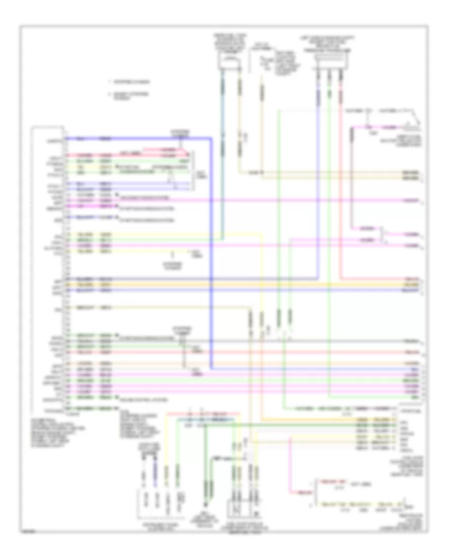
ENGINE PERFORMANCE
5.4L
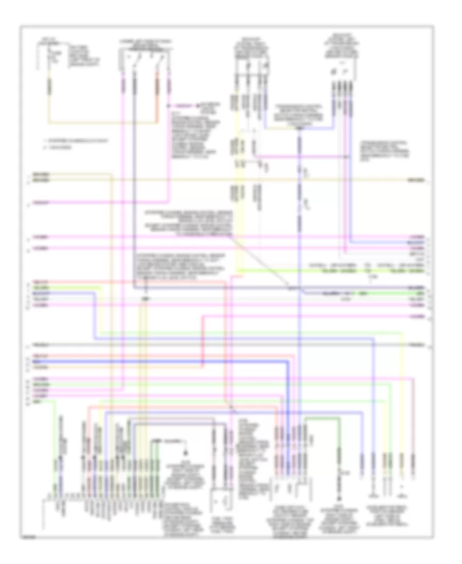
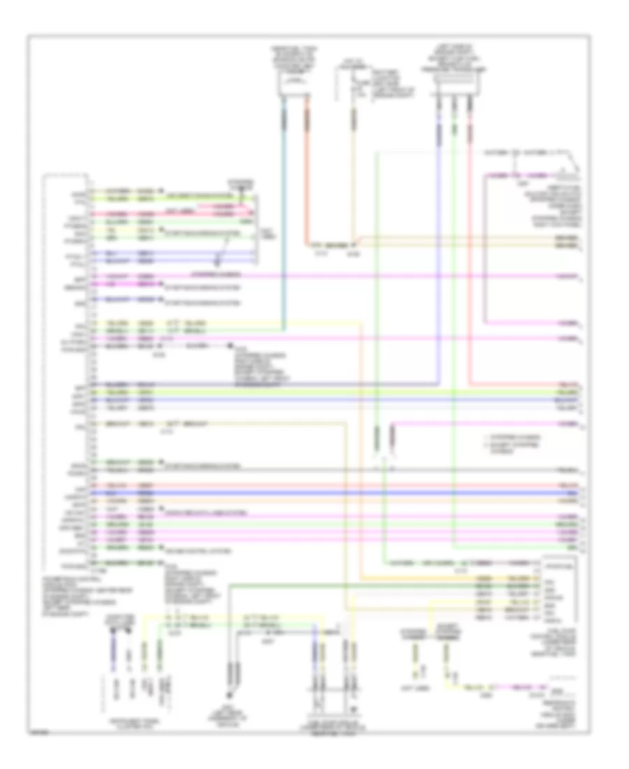
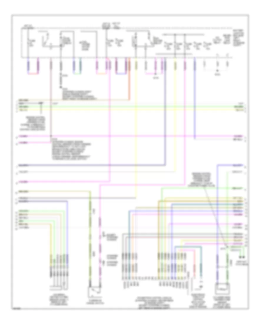
5.4L, Engine Performance Wiring Diagram, with Torqshift (1 of 5) for Ford E-350 Super Duty 2013

List of elements for 5.4L, Engine Performance Wiring Diagram, with Torqshift (1 of 5) for Ford E-350 Super Duty 2013:
- (left side of engine compt) (except flex fuel) brake fluid pressure transducer
- (near fuel tank) evaporative emission (evap) canister vent valve
- (not used)
- Accr
- Air conditioning system
- App1
- App2
- Apprtn1
- Appvref1
- Battery junction box (bjb) (left front of engine compt)
- Bfp
- Bpp
- Bps
- C110
- C175b
- C219
- C263
- C291
- C310a
- Can+
- Can-
- Canv
- Cbb54
- Cbb75
- Ccb08
- Cdc12
- Cdc15
- Cdc35
- Ce114
- Ce302
- Ce326
- Ce336
- Ce515
- Ce608
- Ce912
- Ce913
- Ce914
- Ce924
- Ces09
- Ch302
- Computer data lines system
- Cr167
- Cruise control system
- Ens
- Except stripped chassis
- Fpc
- Fpm
- Fppwr
- Fprtn
- Fuel pump control module (under rear of vehicle, near fuel tank)
- Fuel pump module (under rear of vehicle, near fuel tank)
- Fuel sndr 1
- Fuel sndr rtn 1
- Fuse 10a
- G105 (stripped chassis: right side of engine compt) (except stripped chassis: left front of engine compt)
- G401 (left rear underbody of vehicle)
- Gd120
- Gd128
- Genmon
- Gnd
- Hot at all times
- Hs can-
- Iat
- Inertia fuel shutoff (ifs) switch (stripped chassis: under dash) (except stripped chassis: right kick panel)
- Inj pwrm
- Instrument panel cluster (ipc)
- Isp-r
- Le136
- Maf
- Mafrtn
- Nca
- Pcmrc
- Powertrain control module (stripped chassis: center rear of engine compt) (except stripped chassis: left rear of engine compt)
- Ptioc 1
- Pto
- Ptoeng
- Ptoil
- Ptorpm
- Pwr gnd
- Rca16
- Re136
- Re320
- Re515
- Res08
- Restraints control module (rcm) (under driver's seat)
- S125
- S129
- S407
- Sccs rtn
- Smc
- Smcs
- Smr
- Starting/charging system
- Stripped chassis
- Vdb05
- Ve225
- Ve518
- Ve701
- Ve702
- Ve740
- Ve807
- Vmc05
- Vpwr
- Vpwr fuel
- Vsout
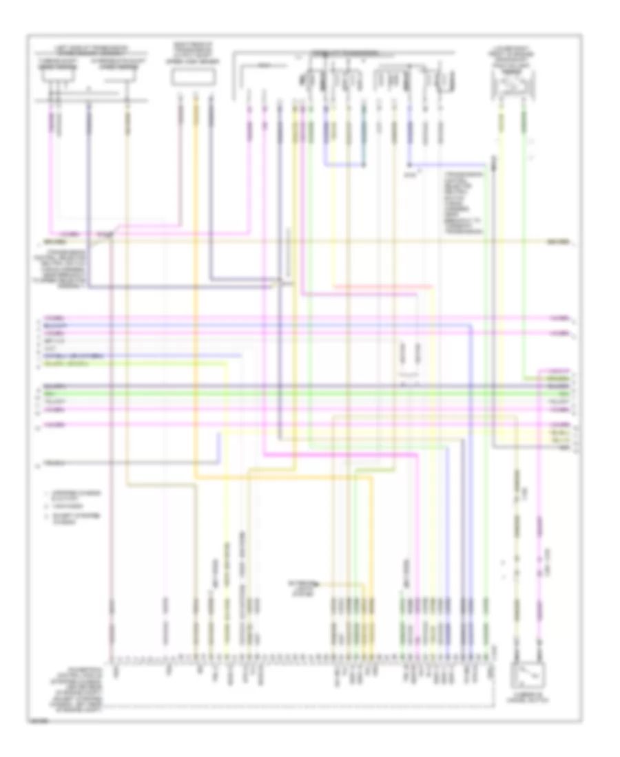
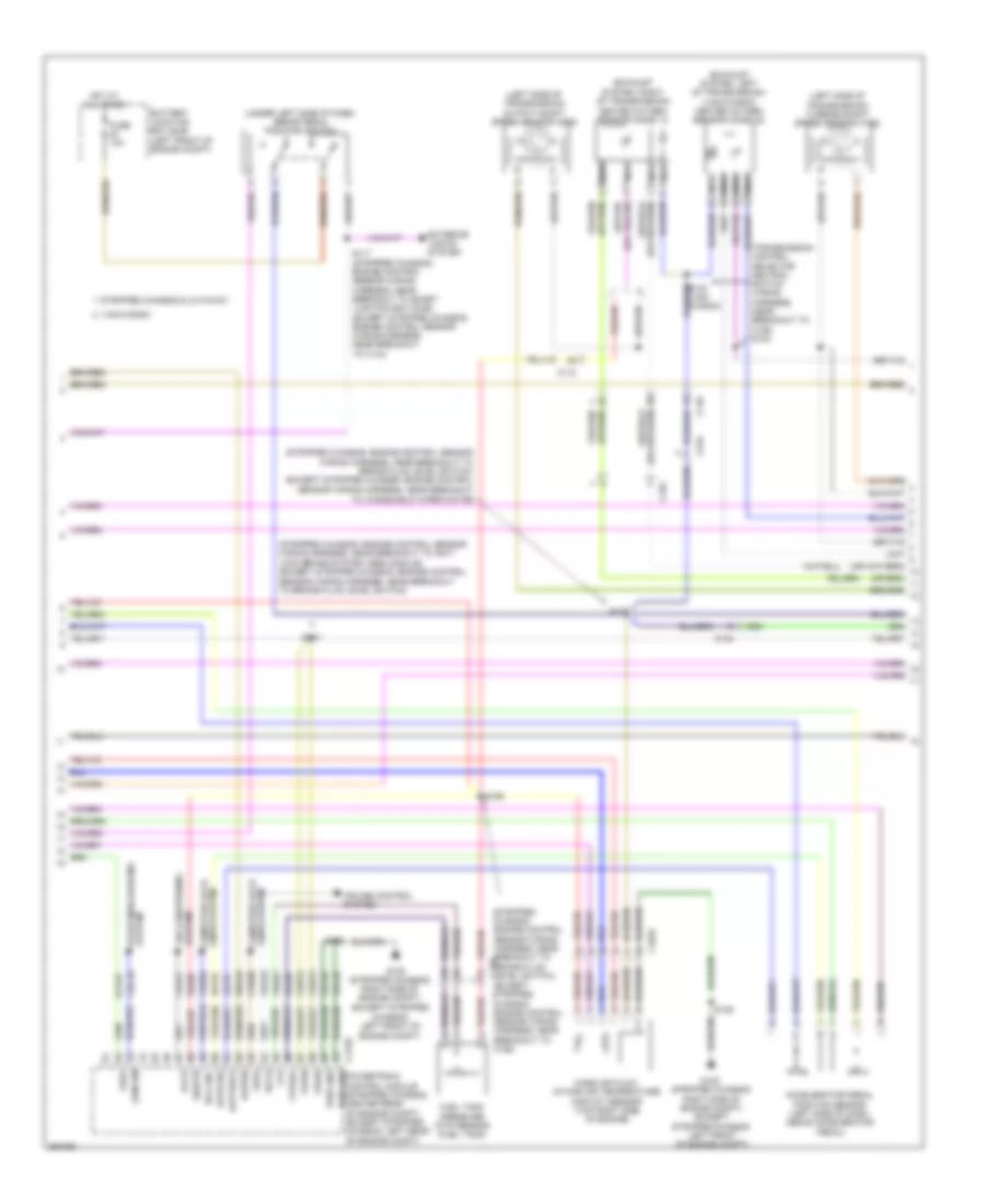
5.4L, Engine Performance Wiring Diagram, with Torqshift (2 of 5) for Ford E-350 Super Duty 2013
List of elements for 5.4L, Engine Performance Wiring Diagram, with Torqshift (2 of 5) for Ford E-350 Super Duty 2013:
- (exhaust system, left of transmission) (van/wagon) heated oxygen sensor (ho2s) 22
- (exhaust system, right of transmission) heated oxygen sensor (ho2s) 12
- (stripped chassis: engine control sensor wiring harness, near breakout to anti- lock brake system (abs) module) (except stripped chassis: engine control
- (stripped chassis: engine control sensor wiring harness, near breakout to brake fluid level switch) (except stripped chassis: engine control
- (transmission control selector neutral switch wiring harness, near breakout to c192)
- (transmission control selector neutral switch wiring harness, near breakout to c192) s104
- (under left side of dash) brake pedal position switch
- (van/wagon) s103
- Accelerator pedal position sensor (left side of dash, above accelerator pedal)
- Accs
- Apprtn2
- Appvref2
- Battery junction box (bjb) (left front of engine compt)
- C1033
- C110
- C134
- C175b
- C192
- Cbb75
- Cdb08
- Cdc10
- Ch421
- Cruise control system
- Exterior lights system
- Feps
- Ftp
- Ftpref
- Fuel tank pressure (ftp) sensor (fuel tank)
- Fuse 10a
- G105 (stripped chassis: right side of engine compt) (except stripped chassis: left front of engine compt)
- Gd120
- Gencom
- Hot at all times
- Hs can+
- Kapwr
- Lca16
- Le137
- Le230
- Level switch) (except stripped chassis: engine control sensor wiring harness, near breakout to c192)
- Lines system computer data
- Mass air flow/ air temperature (maf/iat) sensor (stripped chassis: top right side of engine) (except stripped chassis: center of engine compt)
- Nca
- Powertrain control module (stripped chassis: center rear of engine compt) (except stripped chassis: left rear of engine compt)
- Pwr gnd
- Re137
- Re407
- S117 (stripped chassis: engine control sensor wiring harness, near breakout to smart junction box (sjb)) (except stripped chassis: engine control sensor wiring harness, near breakout to c144)
- S125
- S131
- S137
- S156 (stripped chassis: engine control sensor wiring harness, near breakout to brake fluid
- Sbb46
- Sccs
- Sensor wiring harness, near breakout to brake fluid level switch)
- Sensor wiring harness, near breakout to windshield wiper motor)
- Sigrtn
- Stripped chassis & cutaway
- System air conditioning
- System starting/charging
- Van/wagon
- Vdb04
- Ve922
- Ves10
- Vpwr
- Vref
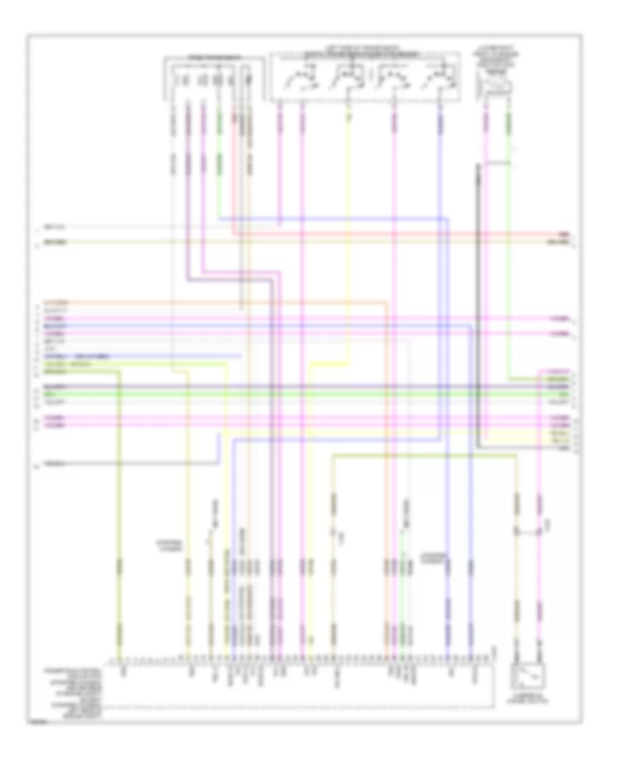
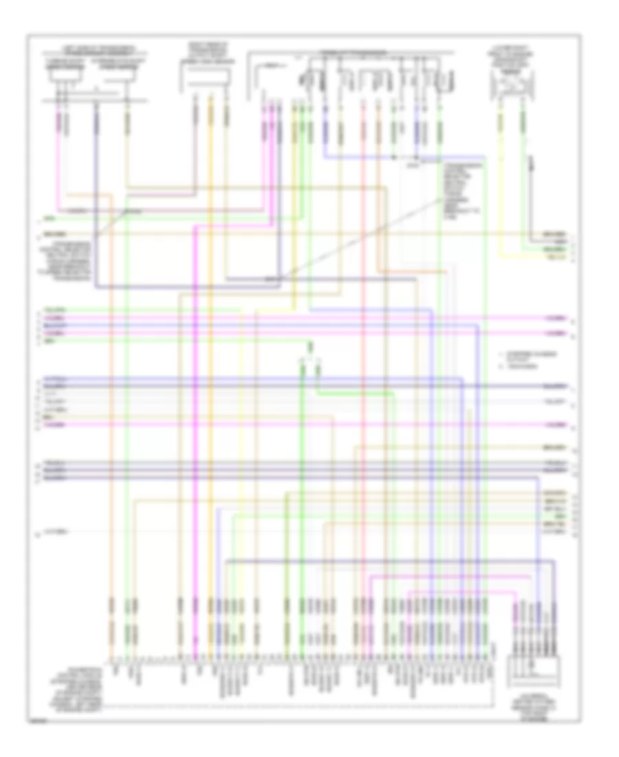
5.4L, Engine Performance Wiring Diagram, with Torqshift (3 of 5) for Ford E-350 Super Duty 2013
List of elements for 5.4L, Engine Performance Wiring Diagram, with Torqshift (3 of 5) for Ford E-350 Super Duty 2013:
- & cutway
- (left side of transmission) speed sensor assembly
- (lower right front of engine) crankshaft position (ckp) sensor
- (not used)
- (or ce239)
- (or ve745)
- (right rear of transmission) output shaft speed (oss) sensor
- (stripped chassis: center rear of engine compt) (except stripped chassis: left rear of engine compt)
- (transmission control selector neutral switch wiring harness, near breakout to speed selector assembly)
- (transmission control selector neutral switch wiring harness, near breakout to torqshift transmission)
- C175t
- C192
- C219
- C291
- Ce223
- Ce234
- Cet05
- Cet06
- Cet07
- Cet08
- Cet09
- Cet21
- Cet22
- Cet25
- Cet34
- Cet41
- Cet50
- Cet51
- Except stripped chassis
- Exterior
- Ho2s-12
- Ho2s-22
- Htr-12
- Htr-22
- Intermediate shaft speed sensor
- Iss
- Le111
- Lights system
- Nca
- Od cncl
- Oss
- Overdrive cancel switch
- Pc-a
- Powertrain control module
- Re406
- Ret04
- Ret24
- Rlc
- S100
- S101
- S102
- Sigrtn
- Sspc a
- Sspc b
- Sspc c
- Sspc d
- Sspc e
- Sspc-a
- Sspc-b
- Sspc-c
- Sspc-d
- Sspc-e
- Stripped chassis
- Tcc
- Tft
- Torqshift transmission
- Tr gnd
- Tr-p
- Tro_n
- Tro_p
- Tspc
- Tss
- Turbine shaft speed sensor
- Van/wagon
- Ve731
- Ve733
- Ve744
- Vet27
- Vet32
- Vet33
- Vref
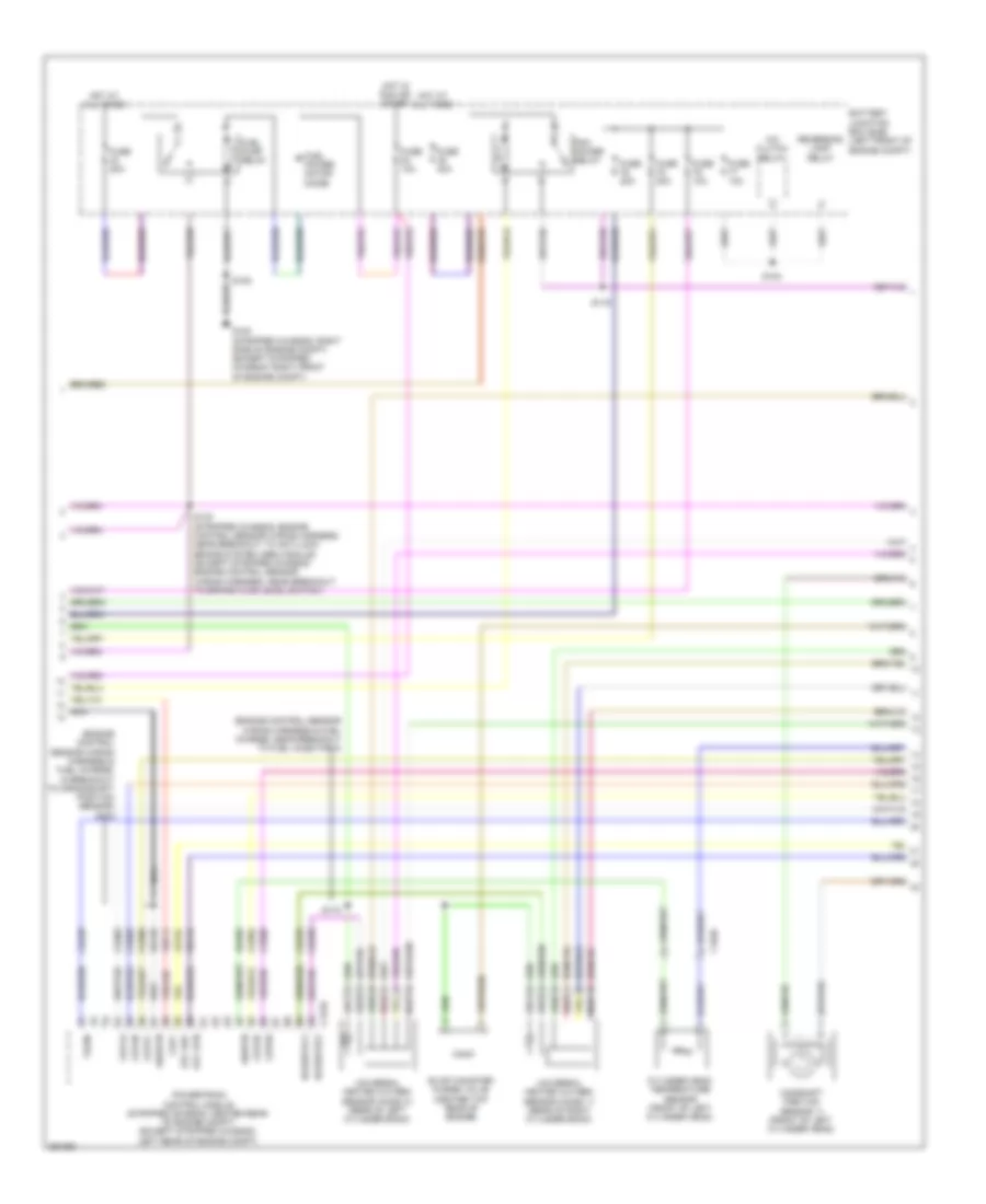
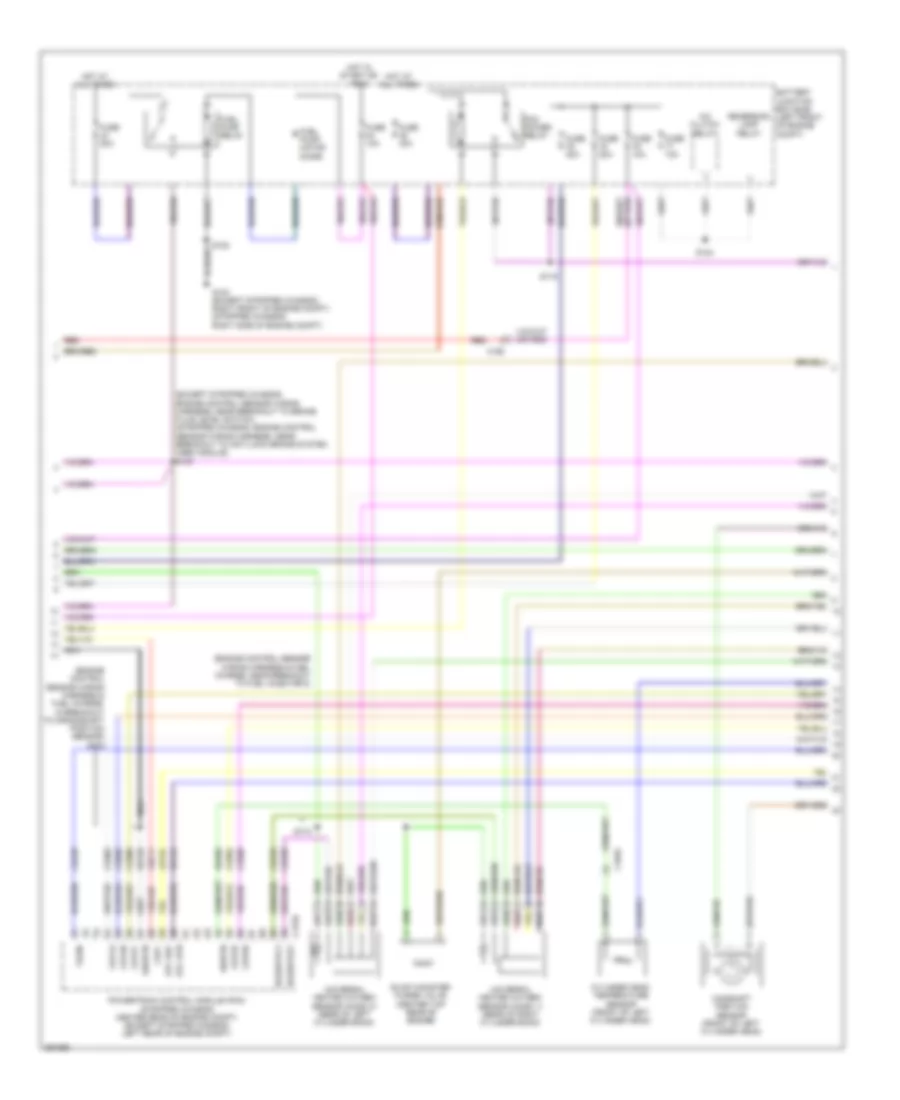
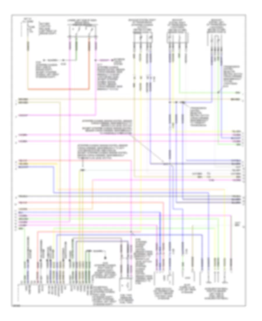
5.4L, Engine Performance Wiring Diagram, with Torqshift (4 of 5) for Ford E-350 Super Duty 2013
List of elements for 5.4L, Engine Performance Wiring Diagram, with Torqshift (4 of 5) for Ford E-350 Super Duty 2013:
- (engine control sensor wiring harness & fuel charge, in breakout to crankshaft position sensor) s178
- (engine control sensor wiring harness & fuel charge, near breakout to fuel injector 8)
- A/c clutch relay
- Battery junction box (bjb) (left front of engine compt)
- C1046
- C175e
- Camshaft position sensor 11 (front of left cylinder head)
- Ce235
- Ce236
- Ce303
- Ce304
- Ce305
- Ce308
- Ce309
- Ce426
- Ckp+
- Cop1a
- Cop2d
- Cop3b
- Cop6e
- Cop7c
- Cylinder head temperature sensor (front of left cylinder head)
- De135
- Etc ref
- Etc rtn
- Evap canister purge valve (center top rear of engine)
- Fuel power motor diode
- Fuel pump relay
- Fuse 10a
- Fuse 20a
- Fuse 40a
- G100 (stripped chassis: right side of engine compt) (except stripped chassis: right front of engine compt)
- Hot at all times
- Hot in run or start
- Le134
- Nca
- Pcm power relay
- Powertrain control module (stripped chassis: center rear of engine compt) (except stripped chassis: left rear of engine compt)
- Re134
- Re405
- Red
- Reversing lamp relay
- S108
- S116
- S124
- S130 (stripped chassis: engine control sensor wiring harness, near breakout to anti-lock brake system (abs) module) (except stripped chassis: engine control sensor wiring harness, near breakout to brake fluid level switch)
- S174
- Shdrtn
- Sigrtn
- Tacm-
- Universal heated oxygen sensor (ho2s) 11 (rear of right cylinder bank)
- Universal heated oxygen sensor (ho2s) 21 (rear of left cylinder bank)
- Uo2shtr11
- Uo2shtr21
- Ve711
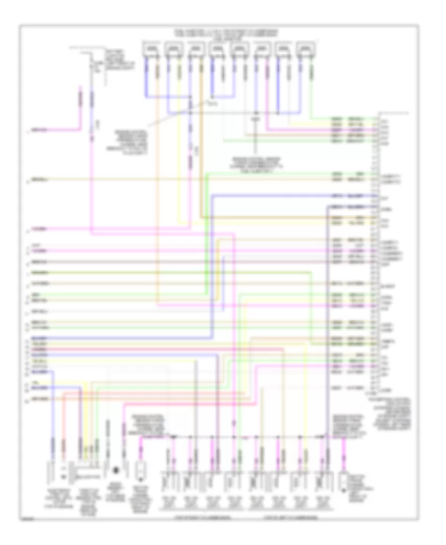
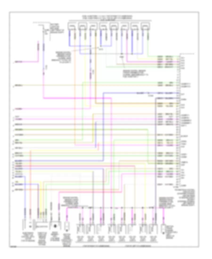
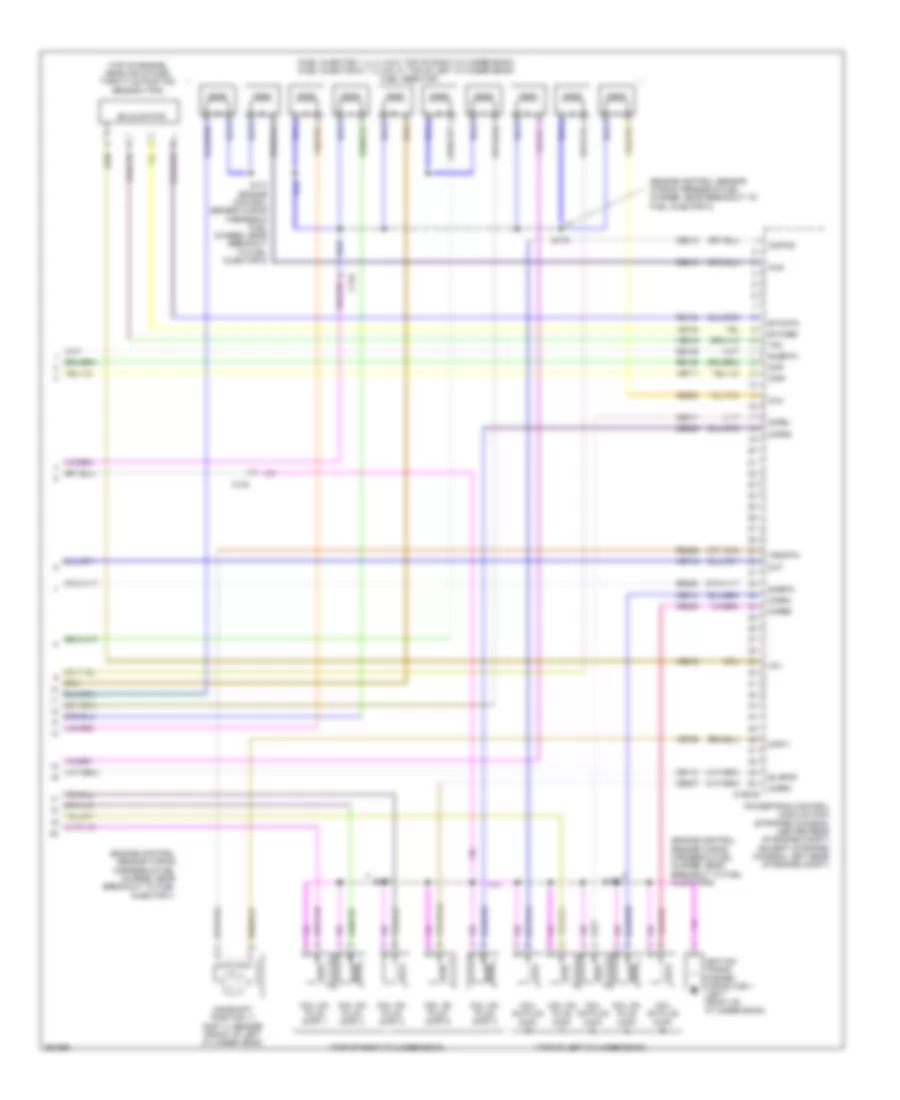
5.4L, Engine Performance Wiring Diagram, with Torqshift (5 of 5) for Ford E-350 Super Duty 2013
List of elements for 5.4L, Engine Performance Wiring Diagram, with Torqshift (5 of 5) for Ford E-350 Super Duty 2013:
- (engine control sensor wiring harness & fuel charge, near breakout to coil on
- (engine control sensor wiring harness & fuel charge, near breakout to coil on plug (cop) 7)
- (engine control sensor wiring harness & fuel charge, near breakout to fuel injector 1)
- (engine control sensor wiring harness & fuel charge, near breakout to fuel injector 2)
- (fuel injector 1, 2, 3 & 4: top of right cylinder bank) (fuel injector 5, 6, 7 & 8: top of left cylinder bank) fuel injector
- (top of left cylinder bank)
- (top of right cylinder bank)
- Battery junction box (bjb) (left front of engine compt)
- C134
- C175e
- Ce113
- Ce205
- Ce206
- Ce207
- Ce208
- Ce209
- Ce210
- Ce211
- Ce212
- Ce306
- Ce307
- Ce310
- Ce412
- Cht
- Ckp-
- Cmp1
- Coil on plug (cop) 1
- Coil on plug (cop) 2
- Coil on plug (cop) 3
- Coil on plug (cop) 4
- Coil on plug (cop) 5
- Coil on plug (cop) 6
- Coil on plug (cop) 7
- Coil on plug (cop) 8
- Cop4g
- Cop5f
- Cop8h
- Electronic throttle control (etc) motor (top of engine)
- Evapcp
- Fuse 15a
- Ignition trans- former capacitor 1 (top right front of engine)
- Ignition trans- former capacitor 2 (left front of engine)
- Inj1
- Inj2
- Inj3
- Inj4
- Inj5
- Inj6
- Inj7
- Inj8
- Knock sensor 1 (ks1) (top rear of engine)
- Ks1+
- Ks1-
- Le448
- Le449
- Le450
- Le451
- Le452
- Le453
- Nca
- Plug (cop) 7)
- Powertrain control module (pcm) (stripped chassis: center rear of engine compt) (except stripped chassis: left rear of engine compt)
- Re135
- Re323
- Re429
- S170
- S173
- S175
- S177
- Solid state
- Tacm+
- Throttle position sensor (tps) (top of engine, near air intake)
- Tp1
- Tp2
- Uo2s11
- Uo2s21
- Uo2sgref11
- Uo2sgref21
- Uo2spc11
- Uo2spc21
- Uo2spct11
- Uo2spct21
- Ve707
- Ve712
- Ve801
- Ve818
- Ve819
- Ve826
- Ve827
- Vrsrtn
5.4L, Engine Performance Wiring Diagram, without Torqshift (1 of 5) for Ford E-350 Super Duty 2013
List of elements for 5.4L, Engine Performance Wiring Diagram, without Torqshift (1 of 5) for Ford E-350 Super Duty 2013:
- (left side of engine compt) (except flex fuel) brake fluid pressure transducer
- (near fuel tank) evaporative emission (evap) canister vent valve
- (not used)
- Accr
- Air conditioning system
- App1
- App2
- Apprtn1
- Appvref1
- Battery junction box (bjb) (left front of engine compt)
- Bfp
- Bpp
- Bps
- C110
- C175b
- C219
- C263
- C291
- C310a
- Canv
- Cbb54
- Cbb75
- Ccb08
- Cdc12
- Cdc15
- Cdc35
- Ce114
- Ce302
- Ce326
- Ce336
- Ce515
- Ce608
- Ce912
- Ce913
- Ce914
- Ce924
- Ces09
- Ch302
- Chassis: left front of engine compt)
- Computer data lines system
- Cr167
- Cruise control system
- Ens
- Except stripped chassis
- Fpc
- Fpm
- Fppwr
- Fprtn
- Fuel
- Fuel pump control module (under rear of vehicle, near fuel tank)
- Fuel pump module (under rear of vehicle, near fuel tank)
- Fuel sndr rtn 1
- Fuse 10a
- G105 (stripped chassis: right side of engine compt) (except stripped
- G105 (stripped chassis: right side of engine compt) (except stripped chassis: left front of engine compt)
- G401 (left rear underbody of vehicle)
- Gd120
- Gd128
- Genmon
- Gnd
- Hot at all times
- Hs can+
- Hs can-
- Iat
- Inertia fuel shutoff (ifs) switch (stripped chassis:
- Inj pwrm
- Instrument panel cluster (ipc)
- Isp-r
- Le136
- Maf
- Mafrtn
- Nca
- Pcmrc
- Powertrain control module (pcm) (stripped chassis: center rear of engine compt) (except stripped chassis: left rear of engine compt)
- Ptioc 1
- Pto
- Ptoeng
- Ptoil
- Ptorpm
- Pwr gnd
- Rca16
- Re136
- Re320
- Re515
- Res08
- Restraints control module (rcm) (under driver's seat)
- Right kick panel)
- S125
- S129
- S407
- Sccs rtn
- Smc
- Smcs
- Smr
- Sndr 1
- Starting/charging system
- Stripped chassis
- Stripped chassis:
- Under dash) (except
- Vdb05
- Ve225
- Ve518
- Ve701
- Ve702
- Ve740
- Ve807
- Vmc05
- Vpwr
- Vpwr fuel
- Vsout
5.4L, Engine Performance Wiring Diagram, without Torqshift (2 of 5) for Ford E-350 Super Duty 2013
List of elements for 5.4L, Engine Performance Wiring Diagram, without Torqshift (2 of 5) for Ford E-350 Super Duty 2013:
- (exhaust system, left of transmission) (van/wagon) heated oxygen sensor (ho2s) 22
- (exhaust system, right of transmission)
- (left side of transmission) output shaft speed sensor (oss)
- (left side of transmission) turbine shaft speed sensor (tss)
- (stripped chassis: engine control sensor wiring harness, near breakout to anti- lock brake system (abs) module) (except stripped chassis: engine control
- (stripped chassis: engine control sensor wiring harness, near breakout to brake fluid level switch) (except stripped chassis: engine control
- (stripped chassis: engine control sensor wiring harness, near breakout to brake fluid level switch) c110 (except stripped chassis: engine control sensor wiring harness, near breakout to c192)
- (stripped chassis: right side of engine compt) (except stripped
- (transmission control selector neutral switch wiring harness, near breakout to c192) s104
- (under left side of dash) brake pedal position switch
- Accelerator pedal position sensor (left side of dash, above accelerator pedal)
- Accs
- Apprtn2
- Appvref2
- Battery junction box (bjb) (left front of engine compt)
- C1033
- C110
- C134
- C175b
- C192
- Cbb75
- Cdb08
- Cdc10
- Ch421
- Chassis: left front of engine compt)
- Chassis: left rear of engine compt)
- Cruise control system
- Exterior lights system
- Feps
- Ftp
- Ftpref
- Fuel tank pressure (ftp) sensor (fuel tank)
- Fuse 10a
- G105
- G105 (stripped chassis: right side of engine compt) (except stripped chassis: left front of engine compt)
- Gd120
- Gencom
- Heated oxygen sensor (ho2s) 12
- Hot at all times
- Hs can+
- Kapwr
- Lca16
- Le137
- Le230
- Lines system computer data
- Mass air flow/ intake air temperature (maf/iat) sensor (top right side of engine)
- Nca
- Pwr gnd
- Pwr gnd powertrain control module (stripped chassis: center rear of engine compt) (except stripped
- Re137
- Re407
- S117 (stripped chassis: engine control sensor wiring harness, near breakout to smart junction box (sjb)) (except stripped chassis: engine control sensor wiring harness, near breakout to c144)
- S125
- S131
- S137
- S156
- Sbb46
- Sccs
- Sensor wiring harness, near breakout to brake fluid level switch)
- Sensor wiring harness, near breakout to windshield wiper motor)
- Sigrtn
- Stripped chassis & cutaway
- System air conditioning
- System starting/charging
- Van/wagon
- Vdb04
- Ve922
- Ves10
- Vpwr
- Vref
5.4L, Engine Performance Wiring Diagram, without Torqshift (3 of 5) for Ford E-350 Super Duty 2013
List of elements for 5.4L, Engine Performance Wiring Diagram, without Torqshift (3 of 5) for Ford E-350 Super Duty 2013:
- (left side of transmission) digital transmission range (dtr) sensor
- (lower right front of engine) crankshaft position (ckp) sensor
- (not used)
- (or ce239)
- (or ve745)
- (stripped chassis: center rear of engine compt) (except stripped chassis: left rear of engine compt)
- 4r75e transmission
- C175t
- C192
- C219
- Ce223
- Ce234
- Ce418
- Cet05
- Cet18
- Cet19
- Cet21
- Cet22
- Cet34
- Epc
- Ho2s-12
- Ho2s-22
- Htr-12
- Htr-22
- N r
- Nca
- Od cncl
- Oss
- Overdrive cancel switch
- Powertrain control module (pcm)
- Re406
- Red
- Sigrtn
- Ssa
- Ssb
- Stripped chassis
- Tcc
- Tft
- Tr1
- Tr2
- Tr3a
- Tr4
- Tro_n
- Tro_p
- Tss
- Ve731
- Ve733
- Vet26
- Vet27
- Vet28
- Vet29
- Vet30
- Vet31
- Vet33
5.4L, Engine Performance Wiring Diagram, without Torqshift (4 of 5) for Ford E-350 Super Duty 2013
List of elements for 5.4L, Engine Performance Wiring Diagram, without Torqshift (4 of 5) for Ford E-350 Super Duty 2013:
- (engine control sensor wiring harness & fuel charge, in breakout to crankshaft position sensor) s178
- (engine control sensor wiring harness & fuel charge, near breakout to fuel injector 8)
- (except stripped chassis: engine control sensor wiring harness, near breakout to brake fluid level switch) (stripped chassis: engine control sensor wiring harness, near breakout to anti-lock brake system (abs) module) s130
- A/c clutch relay
- Battery junction box (bjb) (left front of engine compt)
- C1046
- C175e
- C192
- Camshaft position sensor (front of left cylinder head)
- Ce235
- Ce236
- Ce303
- Ce304
- Ce305
- Ce308
- Ce309
- Ce426
- Ckp+
- Cop1a
- Cop2d
- Cop3b
- Cop6e
- Cop7c
- Cylinder head temperature sensor (front of left cylinder head)
- De135
- Etc ref
- Etc rtn
- Evap canister purge valve (center top rear of engine)
- Fuel pump motor diode
- Fuel pump relay
- Fuse 10a
- Fuse 20a
- Fuse 40a
- G100 (except stripped chassis: right front of engine compt) (stripped chassis: right side of engine compt)
- Hot at all times
- Hot in start or run
- Le134
- Nca
- Pcm power relay
- Powertrain control module (pcm) (stripped chassis: center rear of engine compt) (except stripped chassis: left rear of engine compt)
- Re134
- Re405
- Red
- Reversing lamp relay
- S108
- S116
- S124
- S174
- Shdrtn
- Sigrtn
- Tacm-
- Universal heated oxygen sensor (ho2s) 11 (rear of right cylinder bank)
- Universal heated oxygen sensor (ho2s) 21 (rear of left cylinder bank)
- Uo2shtr11
- Uo2shtr21
- Ve711
5.4L, Engine Performance Wiring Diagram, without Torqshift (5 of 5) for Ford E-350 Super Duty 2013
List of elements for 5.4L, Engine Performance Wiring Diagram, without Torqshift (5 of 5) for Ford E-350 Super Duty 2013:
- (engine control sensor wiring harness & fuel charge, near breakout to coil on
- (engine control sensor wiring harness & fuel charge, near breakout to coil on plug (cop) 7)
- (engine control sensor wiring harness & fuel charge, near breakout to fuel injector 1)
- (engine control sensor wiring harness & fuel charge, near breakout to fuel injector 2)
- (fuel injectors 1, 2, 3 & 4: top of right cylinder bank) (fuel injectors 5, 6, 7 & 8: top of left cylinder bank) fuel injectors
- (top of left cylinder bank)
- (top of right cylinder bank)
- Battery junction box (bjb) (left front of engine compt)
- C1046
- C134
- C175e
- Ce113
- Ce205
- Ce206
- Ce207
- Ce208
- Ce209
- Ce210
- Ce211
- Ce212
- Ce306
- Ce307
- Ce310
- Ce412
- Cht
- Ckp-
- Cmp 11
- Coil on plug (cop) 1
- Coil on plug (cop) 2
- Coil on plug (cop) 3
- Coil on plug (cop) 4
- Coil on plug (cop) 5
- Coil on plug (cop) 6
- Coil on plug (cop) 7
- Coil on plug (cop) 8
- Cop4g
- Cop5f
- Cop8h
- Electronic throttle control (etc) motor (top of engine)
- Evapcp
- Fuse 15a
- Ignition trans- former capacitor 1 (top right front of engine)
- Ignition trans- former capacitor 2 (left front of engine)
- Inj1
- Inj2
- Inj3
- Inj4
- Inj5
- Inj6
- Inj7
- Inj8
- Knock sensor 1 (ks1) (top rear of engine)
- Ks1+
- Ks1-
- Le448
- Le449
- Le450
- Le451
- Le452
- Le453
- Nca
- Plug (cop) 7)
- Powertrain control module (pcm) (stripped chassis: center rear of engine compt) (except stripped chassis: left rear of engine compt)
- Re135
- Re323
- Re429
- S170
- S173
- S175
- S177
- Solid state
- Tacm+
- Throttle position sensor (top of engine, near air intake)
- Tp1
- Tp2
- Uo2s11
- Uo2s21
- Uo2sgref11
- Uo2sgref21
- Uo2spc11
- Uo2spc21
- Uo2spct11
- Uo2spct21
- Ve707
- Ve712
- Ve801
- Ve818
- Ve819
- Ve826
- Ve827
- Vrsrtn
6.8L
6.8L, Engine Performance Wiring Diagram (1 of 5) for Ford E-350 Super Duty 2013
List of elements for 6.8L, Engine Performance Wiring Diagram (1 of 5) for Ford E-350 Super Duty 2013:
- (left side of engine compt) (except flex fuel) brake fluid pressure transducer
- (near fuel tank) evaporative emission (evap) canister vent valve
- (not used)
- Accr
- Air conditioning system
- App1
- App2
- Apprtn1
- Appvref1
- Battery junction box (bjb) (left front of engine compt)
- Bfp
- Bpp
- Bps
- C110
- C1551b
- C219
- C263
- C291
- C310a
- Canv
- Cbb54
- Ccb08
- Cdc12
- Cdc15
- Cdc35
- Ce114
- Ce302
- Ce326
- Ce336
- Ce515
- Ce608
- Ce912
- Ce913
- Ce914
- Ce924
- Ces09
- Cet21
- Cet22
- Ch302
- Chassis
- Computer data lines system
- Cr167
- Cruise control system
- Ens
- Except stripped
- Fpc
- Fpm
- Fppwr
- Fprtn
- Fuel pump control module (under rear of vehicle, near fuel tank)
- Fuel pump module (under rear of vehicle, near fuel tank)
- Fuel sndr 1
- Fuel sndr rtn 1
- Fuse 10a
- G105 (stripped chassis: right side of engine compt) (except stripped chassis: left front of engine compt)
- G401 (left rear underbody of vehicle)
- Gd120
- Gd128
- Genmon
- Gnd
- Hot at all times
- Hs can+
- Hs can-
- Iat
- Inertia fuel shutoff (ifs) switch (under dash)
- Inj pwrm
- Instrument panel cluster (ipc)
- Isp-r
- Le136
- Maf
- Mafrtn
- Nca
- Pcmrc
- Powertrain control module (pcm) (stripped chassis: center rear of engine compt) (except stripped chassis: left rear of engine compt)
- Pto
- Ptoeng
- Ptoic 1
- Ptoic 2
- Ptoind
- Pwr gnd
- Rca16
- Re136
- Re320
- Re515
- Res08
- Restraints control module (rcm) (under driver's seat)
- S129
- S407
- Sccs rtn
- Smc
- Smcs
- Smr
- Starting/ charging system
- Starting/charging system
- Stripped chassis
- Tro n
- Tro p
- Ve225
- Ve518
- Ve701
- Ve702
- Ve740
- Ve807
- Vmc05
- Vpwr fuel
- Vsout
6.8L, Engine Performance Wiring Diagram (2 of 5) for Ford E-350 Super Duty 2013
List of elements for 6.8L, Engine Performance Wiring Diagram (2 of 5) for Ford E-350 Super Duty 2013:
- (exhaust system, left of transmission) (van/wagon) heated oxygen sensor (ho2s) 22
- (exhaust system, right of transmission) (stripped chassis/ cutway) heated oxygen sensor (ho2s) 12
- (exhaust system, right of transmission) (van/wagon) heated oxygen sensor (ho2s) 12
- (stripped chassis: engine control sensor wiring harness, near breakout to anti- lock brake system (abs) module) (except stripped chassis: engine control
- (stripped chassis: engine control sensor wiring harness, near breakout to brake fluid level switch) (except stripped chassis: engine control
- (transmission control selector neutral switch wiring harness, near breakout to c192) (van/wagon) s104
- (transmission control selector neutral switch wiring harness, near breakout to torqshift transmission)
- (under left side of dash) brake pedal position switch
- Accelerator pedal position sensor (left side of dash, above accelerator pedal)
- Accs
- Apprtn2
- Appvref2
- Battery junction box (bjb) (left front of engine compt)
- C110
- C134
- C139
- C1551b
- C192
- Cbb75
- Cdc10
- Cet41
- Ch421
- Cruise control system
- Evap purge valve (top left rear of engine)
- Exterior lights system
- Ftp
- Fuel tank pressure (ftp) sensor (fuel tank)
- Fuse 10a
- G105 (stripped chassis: right side of engine compt) (except stripped chassis: left front of engine compt)
- Gd120
- Gencom
- Hot at all times
- Hs can+
- Hs can-
- Kapwr
- Lca16
- Le137
- Le230
- Level switch) (except stripped chassis: engine control sensor wiring harness, near breakout to c192)
- Lights system exterior
- Mass air flow/ air temperature (maf/iat) sensor (top right side of engine)
- Nca
- Powertrain control module (stripped chassis: right side of engine compt) (except stripped chassis: left front of engine compt)
- Pwr gnd
- Re137
- Re407
- Rlc
- S103
- S117 (stripped chassis: engine control sensor wiring harness, near breakout to smart junction box (sjb)) (except stripped chassis: engine control sensor wiring harness, near breakout to c144)
- S125
- S131
- S137
- S156 (stripped chassis: engine control sensor wiring harness, near breakout to brake fluid
- Sbb46
- Sccs
- Sensor wiring harness, near breakout to brake fluid level switch)
- Sensor wiring harness, near breakout to windshield wiper motor)
- Sigrtn
- System air conditioning
- System data lines computer
- System starting/charging
- Vdb04
- Vdb05
- Ve922
- Ves10
- Vpwr
- Vref
6.8L, Engine Performance Wiring Diagram (3 of 5) for Ford E-350 Super Duty 2013
List of elements for 6.8L, Engine Performance Wiring Diagram (3 of 5) for Ford E-350 Super Duty 2013:
- (left side of transmission) speed sensor assembly
- (lower right front of engine) crankshaft position (ckp) sensor
- (right rear of transmission) output shaft speed (oss) sensor
- (stripped chassis: center rear of engine compt) (except stripped chassis: left rear of engine compt)
- (transmission control selector neutral switch wiring harness, near breakout to c192)
- (transmission control selector neutral switch wiring harness, near breakout to speed selector transmission)
- C1551t
- Ce233
- Ce234
- Ce235
- Ce236
- Ce239
- Cet05
- Cet06
- Cet07
- Cet08
- Cet09
- Cet25
- Cet34
- Cet50
- Cet51
- Cutway
- Ho2s-12
- Ho2s-22
- Htr-12
- Htr-22
- Intermediate shaft speed sensor
- Iss
- Le111
- Le448
- Le449
- Le450
- Le451
- Le452
- Le453
- Nca
- Od cncl
- Oss
- Pc a
- Pc-a
- Powertrain control module
- Re242
- Ret04
- Ret24
- S100
- S101
- S102
- Sig rtn
- Sspc a
- Sspc b
- Sspc c
- Sspc e
- Sspc-a
- Sspc-b
- Sspc-c
- Sspc-d
- Sspc-e
- Stripped chassis/
- Tcc
- Tft
- Torqshift transmission
- Tr gnd
- Tr-p
- Tspc
- Tss
- Turbine shaft speed sensor
- Universal heated oxygen sensor (ho2s) 21 (top right of engine)
- Uo2s-11
- Uo2s-21
- Uo2sgref-11
- Uo2sgref-21
- Uo2shtr-11
- Uo2shtr-21
- Uo2spc-11
- Uo2spc-21
- Uo2spct-11
- Uo2spct-21
- Van/wagon
- Ve731
- Ve733
- Ve744
- Ve745
- Ve826
- Ve827
- Vet27
- Vet32
- Vet33
- Vref
6.8L, Engine Performance Wiring Diagram (4 of 5) for Ford E-350 Super Duty 2013
List of elements for 6.8L, Engine Performance Wiring Diagram (4 of 5) for Ford E-350 Super Duty 2013:
- (engine control sensor wiring harness & fuel charge, in breakout to powertrain control module (pcm)
- (engine control sensor wiring harness & fuel charge, near breakout to evap canister purge valve)
- (info not available)
- A/c clutch relay
- Battery junction box (bjb) (left front of engine compt)
- C1046
- C1551e
- C192
- C219
- C291
- Ce205
- Ce206
- Ce207
- Ce209
- Ce210
- Ce211
- Ce212
- Ce214
- Ce303
- Ce304
- Ce306
- Ce309
- Ce412
- Ce426
- Cop1a
- Cop2e
- Cop4i
- Cop7f
- Cylinder head temperature sensor (front of left cylinder head)
- Electronic throttle control (etc) motor (top left side of engine)
- Except stripped chassis
- Fuel power motor diode
- Fuel pump relay
- Fuse 10a
- Fuse 15a
- Fuse 20a
- Fuse 40a
- G100 (stripped chassis: right side of engine compt) (except stripped chassis: right front of engine compt)
- Hot at all times
- Hot in run or start
- Inj1
- Inj10
- Inj2
- Inj3
- Inj5
- Inj6
- Inj7
- Inj8
- Nca
- Overdrive cancel switch
- Pcm power relay
- Powertrain control module (stripped chassis: center rear of engine compt) (except stripped chassis: left rear of engine compt)
- Rever- sing lamp relay
- S108
- S116
- S124
- S130 (stripped chassis: engine control sensor wiring harness, near breakout to anti-lock brake system (abs) module) (except stripped chassis: engine control sensor wiring harness, near breakout to brake fluid level switch)
- S171
- S172
- Stripped chassis
- Tacm+
- Tacm-
- Universal heated oxygen sensor (ho2s) 11 (rear of left cylinder bank)
6.8L, Engine Performance Wiring Diagram (5 of 5) for Ford E-350 Super Duty 2013
List of elements for 6.8L, Engine Performance Wiring Diagram (5 of 5) for Ford E-350 Super Duty 2013:
- (engine control sensor wiring harness & fuel charge, near breakout to fuel injector 1)
- (engine control sensor wiring harness & fuel charge, near breakout to fuel injector 3)
- (engine control sensor wiring harness & fuel charge, near breakout to fuel injector 6)
- (fuel injector 1, 2, 3, 4 & 5: top of right cylinder bank) (fuel injector 6, 7, 8, 9 & 10: top of left cylinder bank) fuel injector
- (top of engine, near air intake) throttle position sensor (tps)
- (top of left cylinder bank)
- (top of right cylinder bank)
- C134
- C1551e
- Camshaft position 11 (cmp 11) sensor (front of left cylinder head)
- Ce113
- Ce208
- Ce213
- Ce305
- Ce307
- Ce308
- Ce310
- Ce311
- Ce312
- Cht
- Ckp+
- Ckp-
- Cmp11
- Coil on plug (cop)
- Coil on plug (cop) 1
- Coil on plug (cop) 2
- Coil on plug (cop) 3
- Coil on plug (cop) 4
- Coil on plug (cop) 5
- Cop10d
- Cop3g
- Cop5c
- Cop6b
- Cop8h
- Cop9j
- De135
- Etc ref
- Etc rtn
- Evapcp
- Ignition trans- former capacitor 1 (left front of cylinder bank)
- Inj4
- Inj9
- Le134
- Powertrain control module (pcm) (stripped chassis: center rear of engine compt) (except stripped chassis: left rear of engine compt)
- Re134
- Re135
- Re405
- Re429
- S170
- S173 (engine control sensor wiring harness & fuel charge, near breakout to fuel injector 8)
- S175
- S177
- Shdrtn
- Sigrtn
- Solid state
- Tp1
- Tp2
- Ve706
- Ve711
- Ve712
- Ve818
- Ve819
- Vrs rtn