ENGINE PERFORMANCE
3.5L
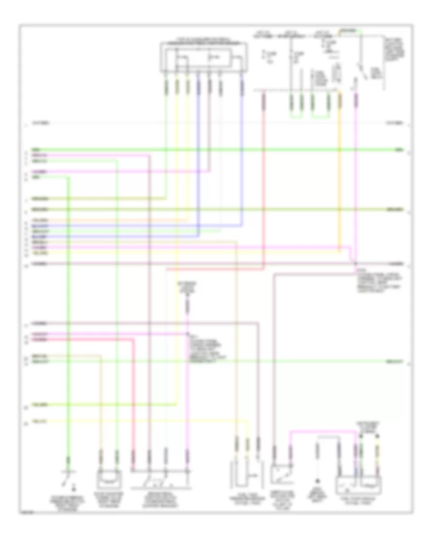
3.5L, Engine Performance Wiring Diagram (1 of 5) for Ford Edge Limited 2008

List of elements for 3.5L, Engine Performance Wiring Diagram (1 of 5) for Ford Edge Limited 2008:
- (in dash panel wiring harness, to headlight junction, near breakout to cooling fan module) s113
- (in dash panel wiring harness, to headlight junction, near breakout to g108) s117
- (not used)
- 10a
- 15a
- 7.5a
- A/c pressure transducer sensor (right front of engine compt)
- Accr
- Acpt
- Air conditioning system
- App1
- App2
- App3
- Appsref1
- Appsref2
- Appsrtn1
- Appsrtn2
- Battery junction box (bjb) (left side of engine compt)
- Boo
- Bps
- C-ref
- C-sigrtn
- C140
- C175b
- Canvnt
- Case gnd
- Cbb30
- Cbb49
- Ccb08
- Ccs09
- Cdb08
- Cdc10
- Cdc12
- Cdc15
- Cdc35
- Ce114
- Ce132
- Ce237
- Ce608
- Ces09
- Cet34
- Ch302
- Computer data lines system
- Cooling fans system
- Cruise control system
- Evap canister vent control solenoid (under left side of vehicle)
- Fan motor ctrl
- Feps
- Fpm
- Ftp sens sig
- Ftptref
- Fuse
- G104 (left front of engine compt)
- G108 (right rear of engine compt)
- G109 (front of engine)
- Gd124
- Gen com
- Gen mon
- Hot at all times
- Hot in start or run
- Hs can+
- Hs can-
- Iat
- Ignition
- Injpwrm
- Joint connector (left rear of engine compt)
- Kapwr
- Le136
- Le137
- Le230
- Le424
- Maf
- Mafrtn
- Mass air flow/intake air temperature (maf/iat) sensor (on intake air duct)
- Overdrive cancel
- Pcm power relay
- Pcm rly ctrl
- Powertrain control module (pcm) (right front of engine)
- Pspt
- Pwr gnd 1
- Pwr gnd 2
- Pwr gnd 3
- Pwr gnd 4
- Pwrgnd
- Re136
- Re137
- Re320
- Re407
- Relay control
- Res08
- S119 (in dash panel wiring harness, to headlight junction, near breakout to g109)
- S120
- S132
- Sbb21
- Sccs
- Sccsrtn
- Sig return
- Smc
- Smrc
- Start
- Starting/ charging system
- Starting/charging system
- Vdb04
- Vdb05
- Ve225
- Ve701
- Ve702
- Ve703
- Ve740
- Ve807
- Ve922
- Vec03
- Ves10
- Vh433
- Vmc05
- Vmv
- Vpwr
- Vpwr1
- Vsout
- Wiper/washer system
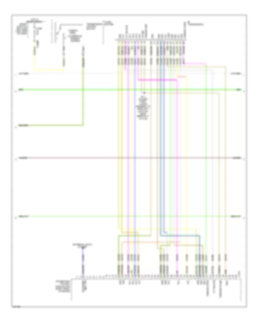
3.5L, Engine Performance Wiring Diagram (2 of 5) for Ford Edge Limited 2008
List of elements for 3.5L, Engine Performance Wiring Diagram (2 of 5) for Ford Edge Limited 2008:
- (top of accelerator pedal) accelerator pedal position sensor
- 10a
- 15a
- Battery junction box (bjb) (left side of engine compt)
- Brake pedal position switch (on brake pedal support bracket)
- Evap canister purge valve (right rear of engine)
- Exterior lights system
- Fuel pump module (in fuel tank)
- Fuel pump motor diode
- Fuel pump relay
- Fuel tank pressure sensor (in fuel tank)
- Fuse
- G300 (behind left rear seat)
- Hot at all times
- Hot in start or run
- Inertia fuel shutoff (ifs) switch (in left "d" pillar)
- Instrument cluster system
- Pnk
- Power steering pressure switch (right front of engine)
- S105 (in dash panel wiring harness, to headlight junction, near breakout to battery junction box)
- S211 (in dash panel wiring harness, to headlight junction, near breakout to joint connector 7)
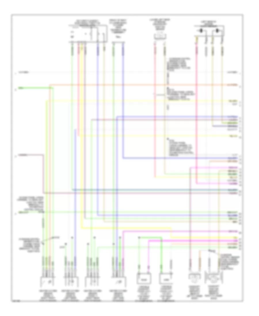
3.5L, Engine Performance Wiring Diagram (3 of 5) for Ford Edge Limited 2008
List of elements for 3.5L, Engine Performance Wiring Diagram (3 of 5) for Ford Edge Limited 2008:
- 1-normal
- 2-overdrive
- 6f transmission
- C175t
- C2280b
- Cet05
- Cet06
- Cet07
- Cet08
- Cet09
- Cet10
- Cet18
- Cet49
- Cls28
- Enable/ disable
- Exterior lights system
- Floor shifter
- Fuse
- Hot in start or run
- Le111
- Lmp ctrl
- Lpc
- Open
- Oss
- Powertrain control module (pcm) (right front of engine)
- Re406
- Ret24
- Reversing
- S111 (in dash panel wiring harness, to headlight junction, near breakout to c134)
- Smart junction box (sjb) (left side of dash)
- Ssa
- Ssb
- Ssc
- Ssd
- Sse
- Tcc
- Tft
- Tft sig rtn
- Tr gnd
- Tr-1
- Tr-2
- Tr-3
- Tr-4
- Transmission comtrol switch
- Tspc
- Tss
- Tss/oss gnd
- Tss/oss vpwr
- Tss/oss/tr gnd
- Vet26
- Vet27
- Vet29
- Vet30
- Vet31
- Vet32
- Vet33
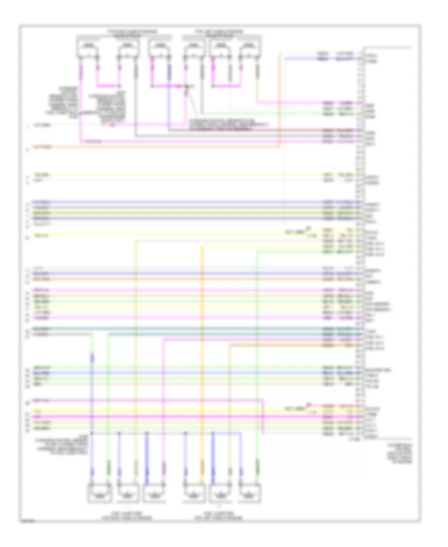
3.5L, Engine Performance Wiring Diagram (4 of 5) for Ford Edge Limited 2008
List of elements for 3.5L, Engine Performance Wiring Diagram (4 of 5) for Ford Edge Limited 2008:
- (front of right cylinder bank) cylinder head temperature sensor
- (in dash panel wiring harness, to headlight junction, near breakout to powertrain control module) s121
- (in engine control sensor & fuel charge wiring harness, near breakout to c139) s130
- (in engine control sensor & fuel charge wiring harness, near breakout to fuel injector 6)
- (left rear of engine) knock sensor
- (lower left rear of engine) crankshaft position sensor
- (on throttle body) electronic throttle control (etc)
- Camshaft position sensor 1 (rear of right cylinder bank)
- Camshaft position sensor 2 (rear of left cylinder bank)
- Heated oxygen sensor (ho2s) 11 (right rear side of engine)
- Heated oxygen sensor (ho2s) 12 (right front side of engine)
- Heated oxygen sensor (ho2s) 21 (left side of engine)
- Heated oxygen sensor (ho2s) 22 (left rear side of engine)
- S122 (in dash panel wiring harness, to headlight junction, near breakout to powertrain control module)
- S125
- S127
- S128
- Tan
- Variable camshaft timing (vct) valve 1 (top front of right cylinder bank)
- Variable camshaft timing (vct) valve 2 (top front of left cylinder bank)
3.5L, Engine Performance Wiring Diagram (5 of 5) for Ford Edge Limited 2008
List of elements for 3.5L, Engine Performance Wiring Diagram (5 of 5) for Ford Edge Limited 2008:
- (in engine control sensor & fuel charge wiring harness, near breakout to camshaft position sensor 2)
- (in engine control sensor & fuel charge wiring harness, near breakout to fuel injector 5) s129
- (not used) c139
- (top left side of engine) coils on plug
- (top right side of engine)
- C175e
- Cd1a
- Cd2c
- Cd3e
- Cd4b
- Cd5d
- Cd6f
- Ce205
- Ce206
- Ce207
- Ce208
- Ce209
- Ce210
- Ce233
- Ce234
- Ce235
- Ce236
- Ce303
- Ce304
- Ce305
- Ce306
- Ce307
- Ce308
- Ce321
- Ce328
- Ce412
- Ce421
- Ce422
- Ce426
- Cht
- Cid1
- Cid2
- Ckp sensor +
- Ckp sensor -
- Coils on plug
- De135
- E-sig return
- Fuel inj 1
- Fuel inj 2
- Fuel inj 3
- Fuel inj 4
- Fuel inj 5
- Fuel inj 6
- Fuel injectors (top left side of engine)
- Fuel injectors (top right side of engine)
- Ho2s-11
- Ho2s-21
- Ho2s12
- Ho2s22
- Htr-11
- Htr-21
- Htr12
- Htr22
- Ks1+
- Ks2-
- Ksl1-
- Ksl2+
- Le134
- Pcvfhc
- Pcvhc
- Powertrain control module (pcm) (right front of engine)
- Re134
- Re135
- Re323
- Re324
- Re405
- Re429
- S124 (in engine control sensor & fuel charge wiring harness, near breakout to ignition transformer capacitor 1)
- S126 (in engine control sensor & fuel charge wiring harness, near breakout to fuel injector 6)
- S131
- Shdrtn
- Tacm+
- Tacm-
- Tp1 ns
- Tp2 ps
- Tpref
- Tprtn
- Vct 1
- Vct 2
- Ve706
- Ve707
- Ve711
- Ve712
- Ve731
- Ve733
- Ve735
- Ve737
- Ve801
- Ve802
- Ve818
- Ve819
- Vrsrtn