ENGINE PERFORMANCE
3.5L
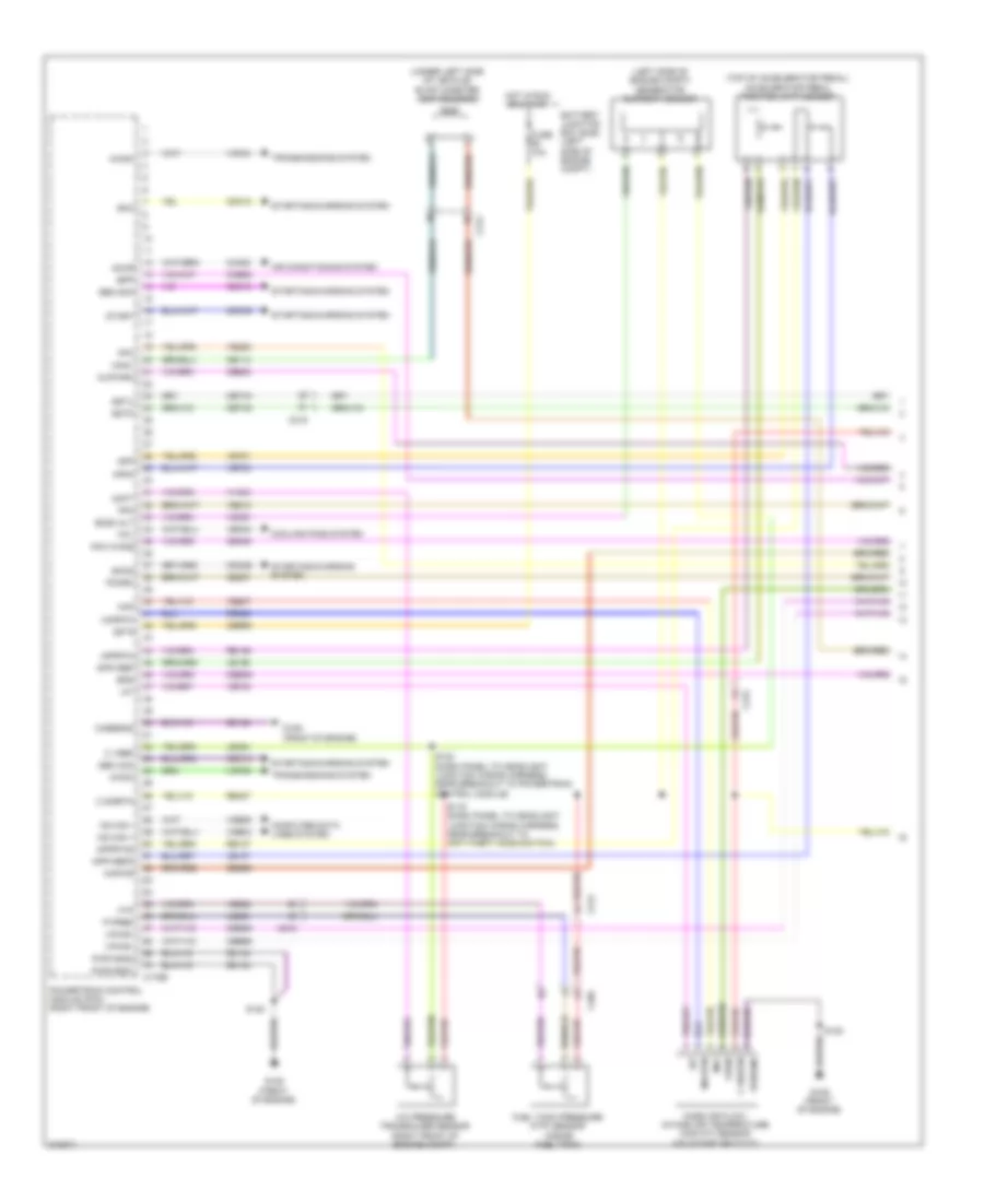
3.5L, Engine Performance Wiring Diagram (1 of 6) for Ford Edge SEL 2011

List of elements for 3.5L, Engine Performance Wiring Diagram (1 of 6) for Ford Edge SEL 2011:
- (left side of engine compt) generator current sensor
- (top of accelerator pedal) accelerator pedal position (app) sensor
- (under left side of vehicle) evap canister vent solenoid
- A/c pressure transducer sensor (right front of engine compt)
- Accr
- Acpt
- Air conditioning system
- App
- App2
- Apprtn
- Apprtn2
- Appvref
- Appvref2
- Awdc
- Awdm
- Battery junction box (bjb) (left side of engine compt)
- Bcs2 alt
- Bpp
- Bps
- C sigrtn
- C vref
- C175b
- C212
- C215
- C405
- Canv
- Casegnd
- Cbb69
- Cbb90
- Ccb08
- Cdc10
- Cdc12
- Cdc15
- Cdc26
- Cdc35
- Ce114
- Ce237
- Ce436
- Ce608
- Ces09
- Cet42
- Cet43
- Ch302
- Computer data lines system
- Cooling fans system
- Fcv
- Fpc
- Fpm
- Ftp
- Ftpref
- Fuel tank pressure (ftp) sensor (inside fuel tank)
- Fuse 10a
- G109 (front of engine)
- Gd124
- Gen com
- Gen mon
- Hot in run or start
- Hs can +
- Hs can -
- Iat
- Injpwrm
- Isp r
- Kapwr
- Le136
- Le137
- Le230
- Le424
- Maf
- Mafrtn
- Mass air flow/ intake air temperature (maf/iat) sensor (on intake air duct)
- Pcm wake
- Pcmrc
- Powertrain control module (pcm) (right front of engine)
- Pwr gnd1
- Pwr gnd2
- Pwrgnd
- Re136
- Re137
- Re320
- Re407
- S119 (dash panel to headlight junction wiring harness, near breakout to anti-theft hood switch)
- S120
- S122 (dash panel to headlight junction wiring harness, near breakout to powertrain control module)
- Sbb86
- Smc
- Smcs
- Sstd
- Sstu
- Start
- Starting/charging system
- Transmissions system
- Vcf34
- Vcf35
- Vdb04
- Vdb05
- Vdc61
- Ve225
- Ve518
- Ve701
- Ve702
- Ve740
- Ve807
- Ve922
- Vec03
- Vh433
- Vpwr
- Vpwr1
3.5L, Engine Performance Wiring Diagram (2 of 6) for Ford Edge SEL 2011
List of elements for 3.5L, Engine Performance Wiring Diagram (2 of 6) for Ford Edge SEL 2011:
- (if equipped) left paddle shifter
- (if equipped) right paddle shifter
- (main wiring harness, near breakout to c215) (w/ paddle shift) s240
- (main wiring harness, near breakout to g206)
- (main wiring harness, near breakout to power point (instrument))
- (right front of engine compt) ambient air temperature sensor
- (steering column) (w/ paddle shift) steering column control module (sccm)
- C110
- C140
- C212
- C213
- C215
- C218b
- C218c c2414d
- C2414a
- C3053
- C310a
- C405
- Ce515
- Ce608
- Cet42
- Cet43
- Clock spring (steering column)
- Cr167
- Ens
- Floor shifter
- Fpc
- Fpm
- Fppwr
- Fprtn
- Fuel level sensor (w/ awd) (top of fuel tank)
- Fuel lvl in 1
- Fuel lvl in 2
- Fuel pump control module (fuel tank)
- Fuel rtn
- Fuel tank unit
- G205 (left side of dash)
- G405 (top of fuel tank)
- Gd476
- Gnd
- Instrument panel cluster (ipc)
- Interior lights system
- Nca
- Pnk
- Re407
- Re515
- Restraints control module (under center console)
- S239 (w/ paddle shift)
- S241 (w/ paddle shift)
- S242 (steering wheel jumper wiring harness)
- S243 (steering wheel jumper wiring harness)
- S244
- Sstd
- Sstu
- Transmission control switch
- Ve225
- Ve518
- Vpwr fuel
- W/ paddle shift
- W/ select shift
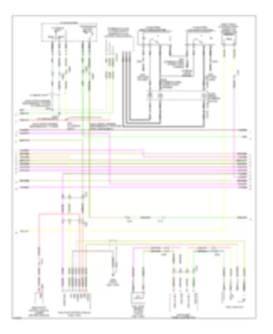
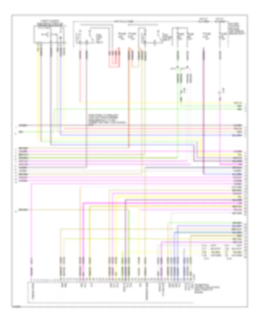
3.5L, Engine Performance Wiring Diagram (3 of 6) for Ford Edge SEL 2011
List of elements for 3.5L, Engine Performance Wiring Diagram (3 of 6) for Ford Edge SEL 2011:
- (dash panel to headlight junction wiring harness, near breakout to high current battery junction box) s105
- (throttle body) electronic throttle control (etc) motor
- Battery junction box (bjb) (left side of engine compt)
- C110
- C140
- C175t
- Ce233
- Ce234
- Cet05
- Cet06
- Cet07
- Cet08
- Cet09
- Cet10
- Cet18
- Cet34
- Cet49
- Fuel pump (fp) relay
- Fuse 10a
- Fuse 15a
- Fuse 20a
- Fuse 7.5a
- Ho2s 12
- Ho2s 22
- Hot at all times
- Htr 12
- Htr 22
- Le111
- Lpc
- Oss
- Pcm power relay
- Powertrain control module (pcm) (right front of engine)
- Re406
- Red
- Ret24
- S113
- S117
- Ssa
- Ssb
- Ssc
- Ssd
- Sse
- Tcc
- Tcs
- Tft
- Tft sig rtn
- Tr 1
- Tr 2
- Tr 3
- Tr 4
- Tspc
- Tss
- Tss/oss vpwr
- Tss/oss/tr gnd
- Ve731
- Ve733
- Vet26
- Vet27
- Vet29
- Vet30
- Vet31
- Vet32
- Vet33
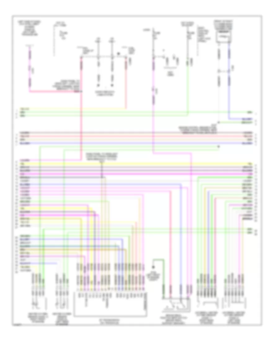
3.5L, Engine Performance Wiring Diagram (4 of 6) for Ford Edge SEL 2011
List of elements for 3.5L, Engine Performance Wiring Diagram (4 of 6) for Ford Edge SEL 2011:
- (dash panel to headlight junction wiring harness, near breakout to c134) s111
- (dash panel to headlight junction wiring harness, near breakout to c215) s235
- (front of right cylinder bank) cylinder head temperature sensor
- (left side of dash) (w/o intelligent access)
- (not used)
- 6f transmission (on transaxle)
- Body control module (bcm) (left kick panel)
- Brake pedal position (bpp) switch (brake pedal support bracket)
- C192
- C215
- C2280b
- C2280f
- Cet05
- Cet06
- Cet07
- Cet08
- Cet09
- Cet10
- Cet18
- Cet49
- Computer data lines system
- Fuel pump (fet)
- Fuse 10a
- Fuse 5a
- G105 (left front of engine compt)
- Heated oxygen sensor (ho2s) 12 (right front of engine)
- Heated oxygen sensor (ho2s) 22 (left rear of engine)
- Hot at all times
- Hot in run or start
- Hs can +
- Hs can -
- Le111
- Lpc
- Micro
- Nca
- Oss
- Passive anti-theft transceiver
- Pcm wake up (fet)
- Re406
- Ret24
- S127 (engine control sensor & fuel charge wiring harness, near breakout to coil on plug 3)
- Ssa
- Ssb
- Ssc
- Ssd
- Sse
- Tcc
- Tft
- Tft sig rtn
- Tr 1
- Tr 2
- Tr 3
- Tr 4
- Tr gnd
- Tspc
- Tss
- Tss/oss gnd
- Tss/oss vpwr
- Universal heated oxygen sensor (ho2s) 11 (right rear of engine)
- Universal heated oxygen sensor (ho2s) 21 (left side of engine)
- Vdb04
- Vdb05
- Vet26
- Vet27
- Vet29
- Vet30
- Vet31
- Vet32
- Vet33
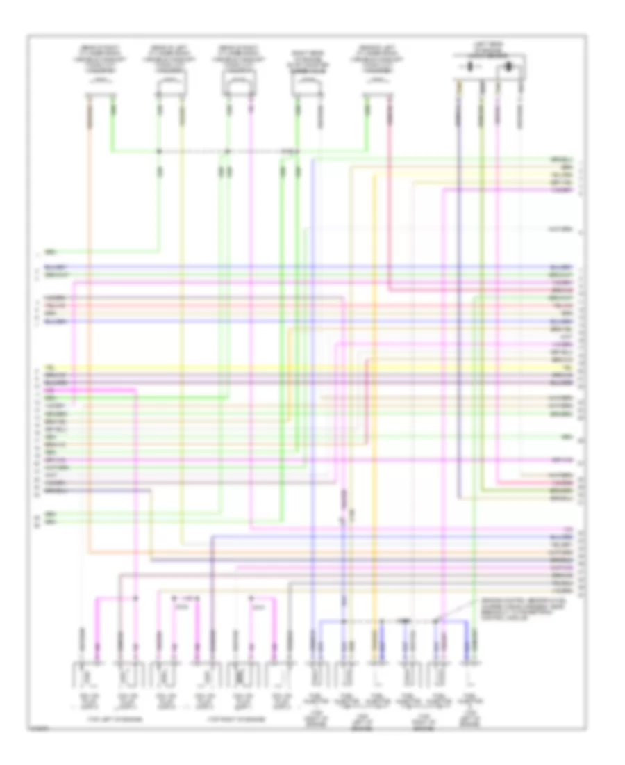
3.5L, Engine Performance Wiring Diagram (5 of 6) for Ford Edge SEL 2011
List of elements for 3.5L, Engine Performance Wiring Diagram (5 of 6) for Ford Edge SEL 2011:
- (engine control sensor & fuel charge wiring harness, near breakout to powertrain control module)
- (left rear of engine) knock sensor
- (rear of left cylinder bank) variable camshaft timing (vct) valve 21
- (rear of left cylinder bank) variable camshaft timing (vct) valve 22
- (rear of right cylinder bank) variable camshaft timing (vct) valve 11
- (rear of right cylinder bank) variable camshaft timing (vct) valve 12
- (right rear of engine) evap canister purge valve
- (top left of engine)
- (top right of engine)
- C140
- Coil on plug (cop) 1
- Coil on plug (cop) 2
- Coil on plug (cop) 3
- Coil on plug (cop) 4
- Coil on plug (cop) 5
- Coil on plug (cop) 6
- Fuel injector
- Fuel injector (top left of engine)
- Fuel injector (top right of engine)
- S124
- S126
- S128
- S131
- Tan
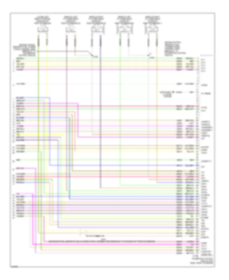
3.5L, Engine Performance Wiring Diagram (6 of 6) for Ford Edge SEL 2011
List of elements for 3.5L, Engine Performance Wiring Diagram (6 of 6) for Ford Edge SEL 2011:
- (engine control sensor & fuel charge wiring harness, near breakout to crankshaft position sensor)
- (engine control sensor & fuel charge wiring harness, near breakout to powertrain control module)
- (lower left rear of engine) crankshaft position sensor
- (rear of left cylinder bank) camshaft position sensor 21
- (rear of left cylinder bank) camshaft position sensor 22
- (rear of right cylinder bank) camshaft position sensor 11
- (rear of right cylinder bank) camshaft position sensor 12
- Aat
- C175e
- Ce113
- Ce205
- Ce206
- Ce207
- Ce208
- Ce209
- Ce210
- Ce235
- Ce236
- Ce303
- Ce304
- Ce305
- Ce306
- Ce307
- Ce308
- Ce412
- Ce421
- Ce422
- Ce426
- Ce442
- Ce443
- Cht
- Ckp+
- Ckp-
- Cmc24
- Cmp11
- Cmp12
- Cmp21
- Cmp22
- Cop1a
- Cop2c
- Cop3e
- Cop4b
- Cop5d
- Cop6f
- De135
- E sigrtn
- Etcref
- Etcrtn
- Evapcp
- Inj 1
- Inj 2
- Inj 3
- Inj 4
- Inj 5
- Inj 6
- Instrument cluster system
- Ks1+
- Ks1-
- Ks2+
- Ks2-
- Le134
- Le448
- Le449
- Le450
- Le451
- Le452
- Le453
- Oil press
- Powertrain control module (pcm) (right front of engine)
- Re134
- Re135
- Re323
- Re324
- Re405
- Re429
- S125
- S130
- S135
- Shdrtn
- Tacm+
- Tacm-
- Tp1
- Tp2
- Uo2s11
- Uo2s21
- Uo2sgref11
- Uo2sgref21
- Uo2shtr11
- Uo2shtr21
- Uo2spc11
- Uo2spc21
- Uo2spct11
- Uo2spct21
- Vct11
- Vct12
- Vct21
- Vct22
- Ve706
- Ve707
- Ve711
- Ve712
- Ve740
- Ve801
- Ve802
- Ve818
- Ve819
- Ve826
- Ve827
- Vrsrtn
- Vrsrtn2
3.7L
3.7L, Engine Performance Wiring Diagram (1 of 6) for Ford Edge SEL 2011
List of elements for 3.7L, Engine Performance Wiring Diagram (1 of 6) for Ford Edge SEL 2011:
- (left side of engine compt) generator current sensor
- (top of accelerator pedal) accelerator pedal position (app) sensor
- (under left side of vehicle) evap canister vent solenoid
- A/c pressure transducer sensor (right front of engine compt)
- Accr
- Acpt
- Air conditioning system
- App
- App2
- Apprtn
- Apprtn2
- Appvref
- Appvref2
- Awdc
- Awdm
- Battery junction box (bjb) (left side of engine compt)
- Bcs2 alt
- Bpp
- Bps
- C sigrtn
- C vref
- C175b
- C212
- C215
- C405
- Canv
- Casegnd
- Cbb69
- Cbb90
- Ccb08
- Cdc10
- Cdc12
- Cdc15
- Cdc26
- Cdc35
- Ce114
- Ce237
- Ce436
- Ce608
- Ces09
- Cet42
- Cet43
- Ch302
- Computer data lines system
- Cooling fans system
- Fcv
- Fpc
- Fpm
- Ftp
- Ftpref
- Fuel tank pressure (ftp) sensor (inside fuel tank)
- Fuse 10a
- G109 (front of engine)
- Gd124
- Gen com
- Gen mon
- Hot in run or start
- Hs can +
- Hs can -
- Iat
- Injpwrm
- Isp r
- Kapwr
- Le136
- Le137
- Le230
- Le424
- Maf
- Mafrtn
- Mass air flow/ intake air temperature (maf/iat) sensor (on intake air duct)
- Pcm wake
- Pcmrc
- Powertrain control module (pcm) (right front of engine)
- Pwr gnd1
- Pwr gnd2
- Pwrgnd
- Re136
- Re137
- Re320
- Re407
- S119 (dash panel to headlight junction wiring harness, near breakout to anti-theft hood switch)
- S120
- S122 (dash panel to headlight junction wiring harness, near breakout to powertrain control module)
- Sbb86
- Smc
- Smcs
- Sstd
- Sstu
- Start
- Starting/charging system
- Transmissions system
- Vcf34
- Vcf35
- Vdb04
- Vdb05
- Vdc61
- Ve225
- Ve518
- Ve701
- Ve702
- Ve740
- Ve807
- Ve922
- Vec03
- Vh433
- Vpwr
- Vpwr1
3.7L, Engine Performance Wiring Diagram (2 of 6) for Ford Edge SEL 2011
List of elements for 3.7L, Engine Performance Wiring Diagram (2 of 6) for Ford Edge SEL 2011:
- (if equipped) left paddle shifter
- (if equipped) right paddle shifter
- (main wiring harness, near breakout to c215) (w/ paddle shift) s240
- (main wiring harness, near breakout to g206)
- (main wiring harness, near breakout to power point (instrument))
- (right front of engine compt) ambient air temperature sensor
- (steering column) (w/ paddle shift) steering column control module (sccm)
- C110
- C140
- C212
- C213
- C215
- C218b
- C218c c2414d
- C2414a
- C3053
- C310a
- C405
- Ce515
- Ce608
- Cet42
- Cet43
- Clock spring (steering column)
- Cr167
- Ens
- Floor shifter
- Fpc
- Fpm
- Fppwr
- Fprtn
- Fuel level sensor (w/ awd) (top of fuel tank)
- Fuel lvl in 1
- Fuel lvl in 2
- Fuel pump control module (fuel tank)
- Fuel rtn
- Fuel tank unit
- G205 (left side of dash)
- G405 (top of fuel tank)
- Gd476
- Gnd
- Instrument panel cluster (ipc)
- Interior lights system
- Nca
- Pnk
- Re407
- Re515
- Restraints control module (under center console)
- S239 (w/ paddle shift)
- S241 (w/ paddle shift)
- S242 (steering wheel jumper wiring harness)
- S243 (steering wheel jumper wiring harness)
- S244
- Sstd
- Sstu
- Transmission control switch
- Ve225
- Ve518
- Vpwr fuel
- W/ paddle shift
- W/ select shift
3.7L, Engine Performance Wiring Diagram (3 of 6) for Ford Edge SEL 2011
List of elements for 3.7L, Engine Performance Wiring Diagram (3 of 6) for Ford Edge SEL 2011:
- (dash panel to headlight junction wiring harness, near breakout to high current battery junction box) s105
- (throttle body) electronic throttle control (etc) motor
- Battery junction box (bjb) (left side of engine compt)
- C110
- C140
- C175t
- Ce233
- Ce234
- Cet05
- Cet06
- Cet07
- Cet08
- Cet09
- Cet10
- Cet18
- Cet34
- Cet49
- Fuel pump (fp) relay
- Fuse 10a
- Fuse 15a
- Fuse 20a
- Fuse 7.5a
- Ho2s 12
- Ho2s 22
- Hot at all times
- Htr 12
- Htr 22
- Le111
- Lpc
- Oss
- Pcm power relay
- Powertrain control module (pcm) (right front of engine)
- Re406
- Red
- Ret24
- S113
- S117
- Ssa
- Ssb
- Ssc
- Ssd
- Sse
- Tcc
- Tcs
- Tft
- Tft sig rtn
- Tr 1
- Tr 2
- Tr 3
- Tr 4
- Tspc
- Tss
- Tss/oss vpwr
- Tss/oss/tr gnd
- Ve731
- Ve733
- Vet26
- Vet27
- Vet29
- Vet30
- Vet31
- Vet32
- Vet33
3.7L, Engine Performance Wiring Diagram (4 of 6) for Ford Edge SEL 2011
List of elements for 3.7L, Engine Performance Wiring Diagram (4 of 6) for Ford Edge SEL 2011:
- (dash panel to headlight junction wiring harness, near breakout to c134) s111
- (dash panel to headlight junction wiring harness, near breakout to c215) s235
- (front of right cylinder bank) cylinder head temperature sensor
- (left side of dash) (w/o intelligent access)
- (not used)
- 6f transmission (on transaxle)
- Body control module (bcm) (left kick panel)
- Brake pedal position (bpp) switch (brake pedal support bracket)
- C192
- C215
- C2280b
- C2280f
- Cet05
- Cet06
- Cet07
- Cet08
- Cet09
- Cet10
- Cet18
- Cet49
- Computer data lines system
- Fuel pump (fet)
- Fuse 10a
- Fuse 5a
- G105 (left front of engine compt)
- Heated oxygen sensor (ho2s) 12 (right front of engine)
- Heated oxygen sensor (ho2s) 22 (left rear of engine)
- Hot at all times
- Hot in run or start
- Hs can +
- Hs can -
- Le111
- Lpc
- Micro
- Nca
- Oss
- Passive anti-theft transceiver
- Pcm wake up (fet)
- Re406
- Ret24
- S127 (engine control sensor & fuel charge wiring harness, near breakout to coil on plug 3)
- Ssa
- Ssb
- Ssc
- Ssd
- Sse
- Tcc
- Tft
- Tft sig rtn
- Tr 1
- Tr 2
- Tr 3
- Tr 4
- Tr gnd
- Tspc
- Tss
- Tss/oss gnd
- Tss/oss vpwr
- Universal heated oxygen sensor (ho2s) 11 (right rear of engine)
- Universal heated oxygen sensor (ho2s) 21 (left side of engine)
- Vdb04
- Vdb05
- Vet26
- Vet27
- Vet29
- Vet30
- Vet31
- Vet32
- Vet33
3.7L, Engine Performance Wiring Diagram (5 of 6) for Ford Edge SEL 2011
List of elements for 3.7L, Engine Performance Wiring Diagram (5 of 6) for Ford Edge SEL 2011:
- (engine control sensor & fuel charge wiring harness, near breakout to powertrain control module)
- (left rear of engine) knock sensor
- (rear of left cylinder bank) variable camshaft timing (vct) valve 21
- (rear of left cylinder bank) variable camshaft timing (vct) valve 22
- (rear of right cylinder bank) variable camshaft timing (vct) valve 11
- (rear of right cylinder bank) variable camshaft timing (vct) valve 12
- (right rear of engine) evap canister purge valve
- (top left of engine)
- (top right of engine)
- C140
- Coil on plug (cop) 1
- Coil on plug (cop) 2
- Coil on plug (cop) 3
- Coil on plug (cop) 4
- Coil on plug (cop) 5
- Coil on plug (cop) 6
- Fuel injector
- Fuel injector (top left of engine)
- Fuel injector (top right of engine)
- S124
- S126
- S128
- S131
- Tan
3.7L, Engine Performance Wiring Diagram (6 of 6) for Ford Edge SEL 2011
List of elements for 3.7L, Engine Performance Wiring Diagram (6 of 6) for Ford Edge SEL 2011:
- (engine control sensor & fuel charge wiring harness, near breakout to crankshaft position sensor)
- (engine control sensor & fuel charge wiring harness, near breakout to powertrain control module)
- (lower left rear of engine) crankshaft position sensor
- (rear of left cylinder bank) camshaft position sensor 21
- (rear of left cylinder bank) camshaft position sensor 22
- (rear of right cylinder bank) camshaft position sensor 11
- (rear of right cylinder bank) camshaft position sensor 12
- Aat
- C175e
- Ce113
- Ce205
- Ce206
- Ce207
- Ce208
- Ce209
- Ce210
- Ce235
- Ce236
- Ce303
- Ce304
- Ce305
- Ce306
- Ce307
- Ce308
- Ce412
- Ce421
- Ce422
- Ce426
- Ce442
- Ce443
- Cht
- Ckp+
- Ckp-
- Cmc24
- Cmp11
- Cmp12
- Cmp21
- Cmp22
- Cop1a
- Cop2c
- Cop3e
- Cop4b
- Cop5d
- Cop6f
- De135
- E sigrtn
- Etcref
- Etcrtn
- Evapcp
- Inj 1
- Inj 2
- Inj 3
- Inj 4
- Inj 5
- Inj 6
- Instrument cluster system
- Ks1+
- Ks1-
- Ks2+
- Ks2-
- Le134
- Le448
- Le449
- Le450
- Le451
- Le452
- Le453
- Oil press
- Powertrain control module (pcm) (right front of engine)
- Re134
- Re135
- Re323
- Re324
- Re405
- Re429
- S125
- S130
- S135
- Shdrtn
- Tacm+
- Tacm-
- Tp1
- Tp2
- Uo2s11
- Uo2s21
- Uo2sgref11
- Uo2sgref21
- Uo2shtr11
- Uo2shtr21
- Uo2spc11
- Uo2spc21
- Uo2spct11
- Uo2spct21
- Vct11
- Vct12
- Vct21
- Vct22
- Ve706
- Ve707
- Ve711
- Ve712
- Ve740
- Ve801
- Ve802
- Ve818
- Ve819
- Ve826
- Ve827
- Vrsrtn
- Vrsrtn2