ENGINE PERFORMANCE
2.0L TURBO
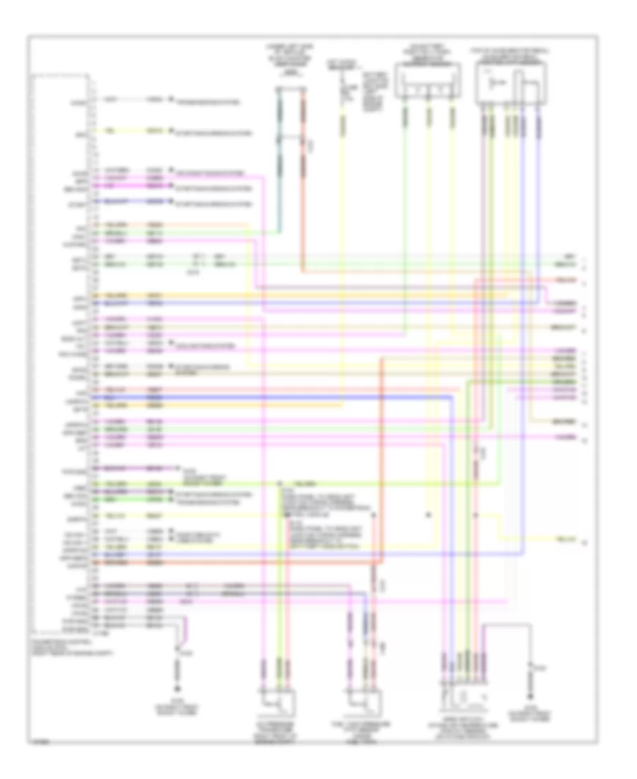
2.0L Turbo, Engine Performance Wiring Diagram (1 of 5) for Ford Edge Sport 2014

List of elements for 2.0L Turbo, Engine Performance Wiring Diagram (1 of 5) for Ford Edge Sport 2014:
- Aat
- Accelerator pedal position (app) sensor (top of accelerator pedal)
- Accr
- Acpt
- Air conditioning system
- App1
- App2
- Apprtn
- Apprtn2
- Appvref
- Appvref2
- Battery junction box (bjb) (left side of engine compt)
- Bcs2alt
- Bpp
- Bps
- C1381b
- C140
- C212
- Canv
- Cbb69
- Cbb90
- Ccb08
- Cdc12
- Cdc15
- Cdc26
- Cdc35
- Ce114
- Ce233
- Ce237
- Ce436
- Ces09
- Cet40
- Ch302
- Computer data lines system
- Cooling fans system
- Evap canister vent valve (under left side of vehicle)
- Evapcp diode
- Fcv
- Fpc
- Fpm
- Fuse 10a
- Fuse 15a
- Fuse 20a
- Fuse 7.5a
- G109 (on right front shock tower)
- Gd124
- Genmon
- Heated oxygen sensor (ho2s) 12 (in exhaust, downstream of catalytic converter)
- Ho2s12
- Hot at all times
- Hot in start or run
- Hs can+
- Hs can-
- Htr12
- Isp-r
- Le136
- Le137
- Le230
- Le424
- Nca
- Pcm power relay
- Pcm wake
- Pcmrc
- Power distribution system
- Powertrain control module (pcm) (right rear of engine compt)
- Pwr gnd
- Re136
- Re137
- Re407
- S108
- S118
- S120
- Sigrtn
- Smc
- Smcs
- Start
- Starting/charging system
- Transmissions system
- Trsw-pn
- Vdb04
- Vdb05
- Vdc61
- Ve225
- Ve518
- Ve701
- Ve702
- Ve731
- Vec03
- Vh407
- Vh433
- Vpwr
- Vref
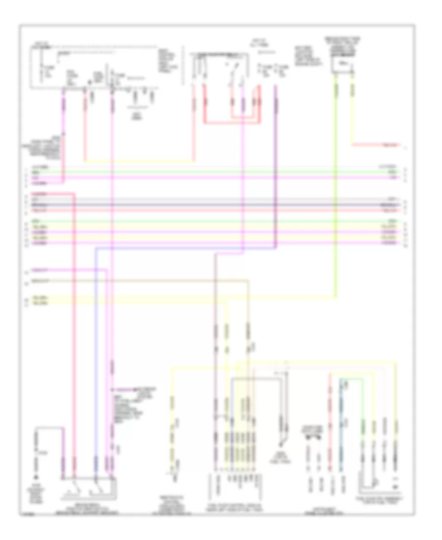
2.0L Turbo, Engine Performance Wiring Diagram (2 of 5) for Ford Edge Sport 2014
List of elements for 2.0L Turbo, Engine Performance Wiring Diagram (2 of 5) for Ford Edge Sport 2014:
- (behind right side of front grille) ambient air temperature (aat) sensor
- (not used)
- Battery junction box (bjb) (left side of engine compt)
- Body control module (bcm) (left kick panel)
- Brake pedal position (bpp) switch (brake pedal support bracket)
- C212
- C213
- C215
- C2280b
- C2280f
- C310a
- C405
- Ce515
- Ce608
- Computer data lines system
- Cr167
- Ens
- Exterior lights system
- Fp pwr
- Fp rtn
- Fpc
- Fpm
- Fuel lvl 1
- Fuel pump (fet)
- Fuel pump (fp) assembly (top of fuel tank)
- Fuel pump (fp) relay
- Fuel pump control module (near left side of fuel tank)
- Fuel rtn
- Fuse 10a
- Fuse 15a
- Fuse 5a
- G109 (on right front shock tower)
- G405 (top of fuel tank)
- Gd476
- Gnd
- Hot at all times
- Hs can +
- Hs can -
- Instrument panel cluster (ipc)
- Micro
- Nca
- Pcm wake up (fet)
- Re515
- Red
- Restraints control module (rcm) (under front of center console)
- S120
- S235 (dash panel to headlight junction wiring harness, near breakout to c215)
- S267 (w/ intelligent access) (main wiring harness, near breakout to g205)
- Ve225
- Ve518
- Vpwr fuel
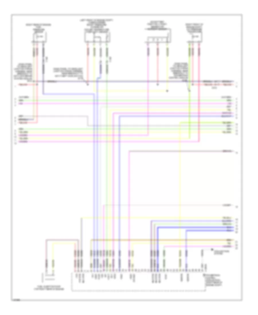
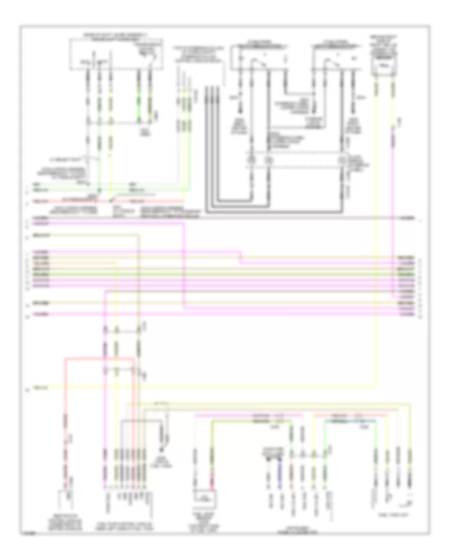
2.0L Turbo, Engine Performance Wiring Diagram (3 of 5) for Ford Edge Sport 2014
List of elements for 2.0L Turbo, Engine Performance Wiring Diagram (3 of 5) for Ford Edge Sport 2014:
- (dash panel to headlight junction wiring harness, near breakout to anti-lock brake system module) s142
- (dash panel to headlight junction wiring harness, near breakout to anti-theft hood switch) s119
- (dash panel to headlight junction wiring harness, near breakout to powertrain control module) s122
- (left front of engine compt) turbocharger boost pressure/ charge air cooler temperature (tcbp/cact) sensor
- (on battery positive (+) post) generator current sensor
- (right front of engine compt) a/c pressure transducer
- (right rear of engine) fuel pressure sensor
- C1381e
- C140
- C212
- Cact
- Ce226
- Cooling fans system
- Ect
- Etcref
- Frp
- Fuel injection pump (top right rear of engine)
- Fvr
- Fvr rtn
- Iat
- Inj1 rtn
- Inj2 rtn
- Inj3 rtn
- Inj4 rtn
- Le134
- Le238
- Le423
- Le458
- Lin
- Powertrain control module (pcm) (right rear of engine compt)
- Re205
- Re206
- Re207
- Re208
- Re226
- Re320
- Re454
- Sigrtn
- Tcbp
- Tcby
- Tp1
- Vdb10
- Ve716
- Ve727
- Ve740
- Ve803
- Ve804
- Ve818
- Ve821
- Ve836
- Vref
- Wvs
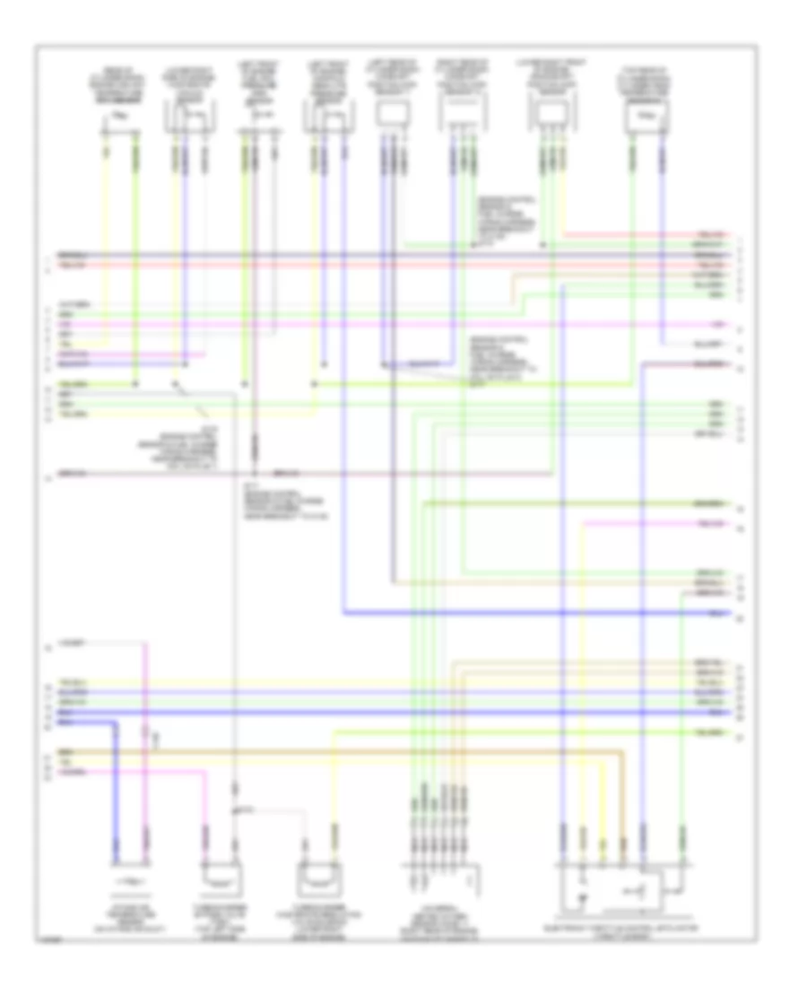
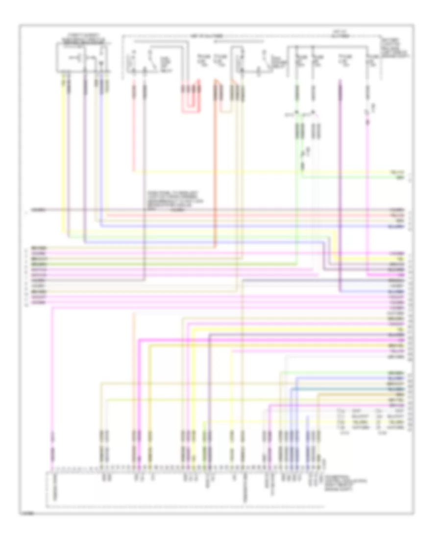
2.0L Turbo, Engine Performance Wiring Diagram (4 of 5) for Ford Edge Sport 2014
List of elements for 2.0L Turbo, Engine Performance Wiring Diagram (4 of 5) for Ford Edge Sport 2014:
- (engine control sensor & fuel charge wiring harness, near breakout to c140) s170
- (engine control sensor & fuel charge wiring harness, near breakout to coil on plug 3) s177
- (left front of engine) fuel rail pressure (frp) sensor
- (left front of engine) manifold absolute pressure sensor
- (left rear of cylinder bank) camshaft position (cmp) sensor 11
- (lower right front of engine) crankshaft position (ckp) sensor
- (lower right side of engine) wastegate vacuum sensor
- (rear of cylinder bank) engine coolant temperature (ect) sensor
- (right rear of cylinder bank) camshaft position (cmp) sensor 12
- (top rear of cylinder bank) cylinder head temperature sensor 2
- C140
- Electronic throttle control (etc) motor (throttle body)
- Intake air temperature sensor (on intake air duct)
- Nca
- S171 (engine control sensor & fuel charge wiring harness, near breakout to c140)
- S172
- S176 (engine control sensor & fuel charge wiring harness, near breakout to coil on plug 1)
- Turbocharger bypass valve (tcbv) (top left side of engine)
- Turbocharger wastegate regulating valve solenoid (lower right side of engine)
- Universal heated oxygen sensor (ho2s) 11 (right rear of engine, on exhaust manifold)
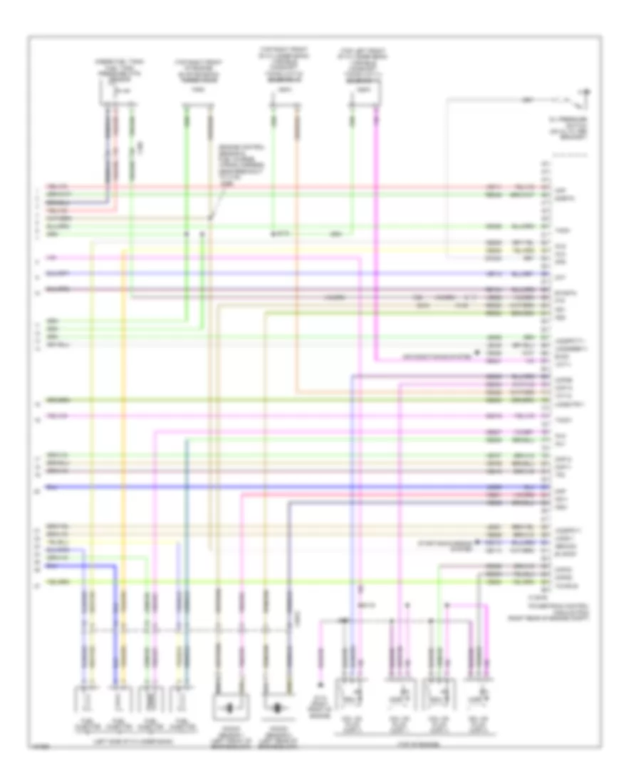
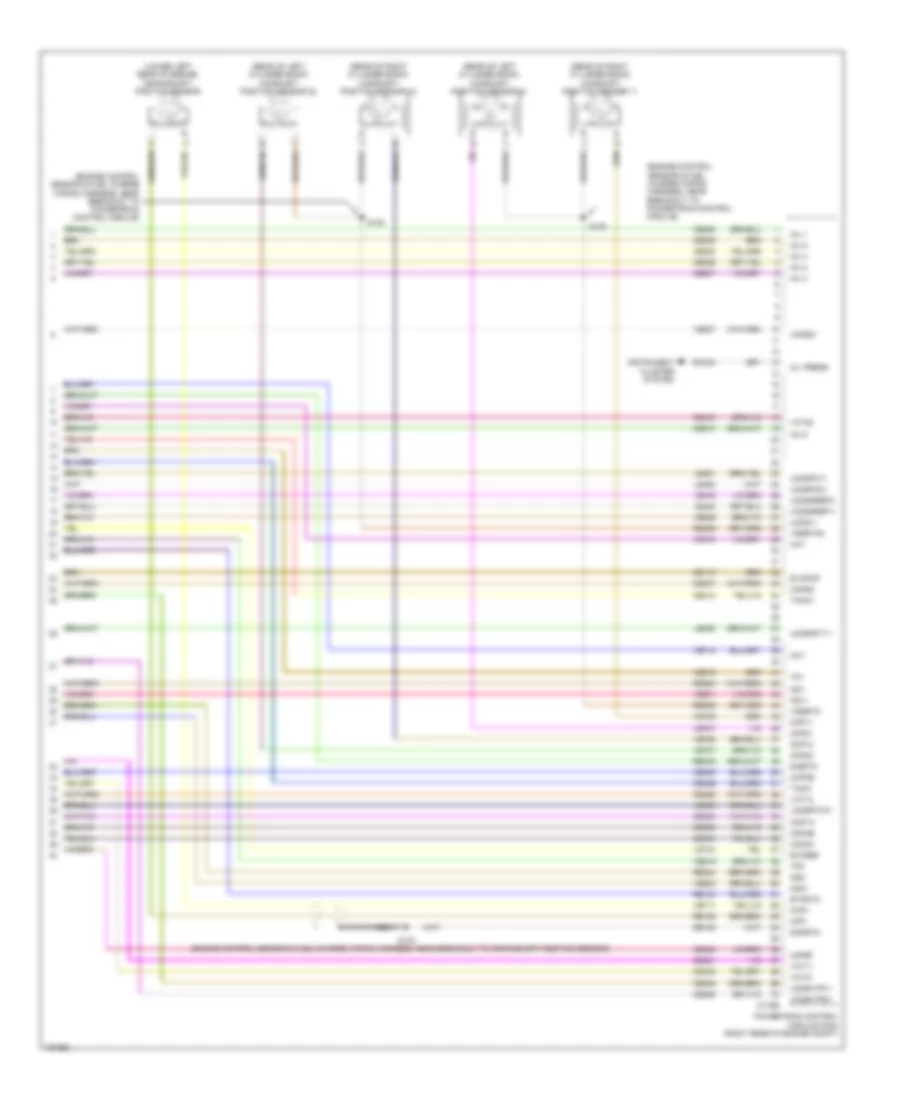
2.0L Turbo, Engine Performance Wiring Diagram (5 of 5) for Ford Edge Sport 2014
List of elements for 2.0L Turbo, Engine Performance Wiring Diagram (5 of 5) for Ford Edge Sport 2014:
- (engine control sensor & fuel charge wiring harness, near breakout to c140)
- (inside fuel tank) fuel tank pressure (ftp) sensor
- (left side of cylinder bank)
- (top left front of cylinder bank) variable camshaft timing (vct11) solenoid 11
- (top of engine)
- (top right front of cylinder bank) variable camshaft timing (vct12) solenoid 12
- (top right front of engine) evap emission purge valve
- Air conditioning system
- C1033
- C1381e
- C140
- C212
- C405
- Cdc10
- Ce113
- Ce205
- Ce206
- Ce207
- Ce208
- Ce235
- Ce303
- Ce304
- Ce305
- Ce306
- Ce412
- Ce421
- Ce422
- Ce426
- Cht
- Ckp
- Cmc24
- Cmp11
- Cmp12
- Coil on plug (cop) 1
- Coil on plug (cop) 2
- Coil on plug (cop) 3
- Coil on plug (cop) 4
- Cop1a
- Cop2d
- Cop3b
- Cop4c
- Etcrtn
- Evapcp
- Evdc
- Ftp
- Fuel injector
- G110 (right front of engine)
- Gencom
- Inj1
- Inj2
- Inj3
- Inj4
- Knock sensor 1 (left front of engine block)
- Knock sensor 2 (left rear of engine block)
- Ks1+
- Ks1-
- Ks2+
- Ks2-
- Le329
- Le448
- Le451
- Le452
- Map
- Oil pressure switch (on oil filter bracket)
- Ops
- Powertrain control module (pcm) (right rear of engine compt)
- Re134
- Re323
- Re324
- Re405
- S169
- S173
- S174
- S175
- Sigrtn
- Starting/charging system
- Tacm+
- Tacm-
- Tcwrvs
- Tp2
- Uo2s11
- Uo2sgref11
- Uo2shtr11
- Uo2spc11
- Uo2spct11
- Vct11
- Vct12
- Ve462
- Ve706
- Ve707
- Ve711
- Ve712
- Ve801
- Ve802
- Ve819
- Ve824
- Ve826
- Ve922
3.5L
3.5L, Engine Performance Wiring Diagram (1 of 6) for Ford Edge Sport 2014
List of elements for 3.5L, Engine Performance Wiring Diagram (1 of 6) for Ford Edge Sport 2014:
- (on battery positive (+) post) generator current sensor
- (top of accelerator pedal) accelerator pedal position (app) sensor
- (under left side of vehicle) evap canister vent valve
- A/c pressure transducer (right front of engine compt)
- Accr
- Acpt
- Air conditioning system
- App1
- App2
- Apprtn
- Apprtn2
- Appvref
- Appvref2
- Awdc
- Awdm
- Battery junction box (bjb) (left side of engine compt)
- Bcs2 alt
- Bpp
- Bps
- C175b
- C212
- C215
- C405
- Canv
- Cbb69
- Cbb90
- Ccb08
- Cdc10
- Cdc12
- Cdc15
- Cdc26
- Cdc35
- Ce114
- Ce237
- Ce436
- Ce608
- Ces09
- Cet42
- Cet43
- Ch302
- Computer data lines system
- Cooling fans system
- Fcv
- Fpc
- Fpm
- Ftp
- Ftpref
- Fuel tank pressure (ftp) sensor (inside fuel tank)
- Fuse 10a
- G109 (on right front shock tower)
- Gd124
- Gen com
- Gen mon
- Hot in run or start
- Hs can +
- Hs can -
- Iat
- Injpwrm
- Isp r
- Kapwr
- Le136
- Le137
- Le230
- Le424
- Maf
- Mafrtn
- Mass air flow/ intake air temperature (maf/iat) sensor (on intake air duct)
- Pcm wake
- Pcmrc
- Powertrain control module (pcm) (right rear of engine compt)
- Pwr gnd
- Re136
- Re137
- Re320
- Re407
- S119 (dash panel to headlight junction wiring harness, near breakout to anti-theft hood switch)
- S120
- S122 (dash panel to headlight junction wiring harness, near breakout to powertrain control module)
- Sbb86
- Sigrtn
- Smc
- Smcs
- Sstd
- Sstu
- Start
- Starting/charging system
- Transmissions system
- Vcf34
- Vcf35
- Vdb04
- Vdb05
- Vdc61
- Ve225
- Ve518
- Ve701
- Ve702
- Ve740
- Ve807
- Ve922
- Vec03
- Vh433
- Vpwr
- Vref
3.5L, Engine Performance Wiring Diagram (2 of 6) for Ford Edge Sport 2014
List of elements for 3.5L, Engine Performance Wiring Diagram (2 of 6) for Ford Edge Sport 2014:
- (base of shift lever assembly) brake shift interlock
- (behind right side of front grille) ambient air temperature sensor
- (if equipped) left paddle shifter
- (if equipped) right paddle shifter
- (main wiring harness, near breakout to accessory protocol interface module)
- (main wiring harness, near breakout to c215) (w/ paddle shift) s240
- (main wiring harness, near breakout to g206)
- (not used)
- (top of steering column) (w/ paddle shift) steering column control module (sccm)
- C140
- C212
- C213
- C218b
- C218c c2414d
- C2414a
- C3053
- C310a
- C405
- Ce515
- Ce608
- Cet42
- Cet43
- Clock spring (steering wheel)
- Computer data lines system
- Cr167
- Ens
- Fpc
- Fpm
- Fppwr
- Fprtn
- Fuel level sensor (awd) (top right side of fuel tank)
- Fuel lvl in 1
- Fuel lvl in 2
- Fuel pump control module (near left side of fuel tank)
- Fuel rtn
- Fuel tank unit
- G205 (right center of dash)
- G405 (top of fuel tank)
- Gd476
- Gnd
- Hs can +
- Hs can -
- Instrument panel cluster (ipc)
- Interior lights system
- Nca
- Pnk
- Re407
- Re515
- Restraints control module (under front of center console)
- S239 (w/ paddle shift)
- S241 (w/ paddle shift)
- S242 (steering wheel jumper wiring harness)
- S243 (steering wheel jumper wiring harness)
- S244
- Sstd
- Sstu
- Transmission control switch
- Ve225
- Ve518
- Vpwr fuel
- W/ select shift
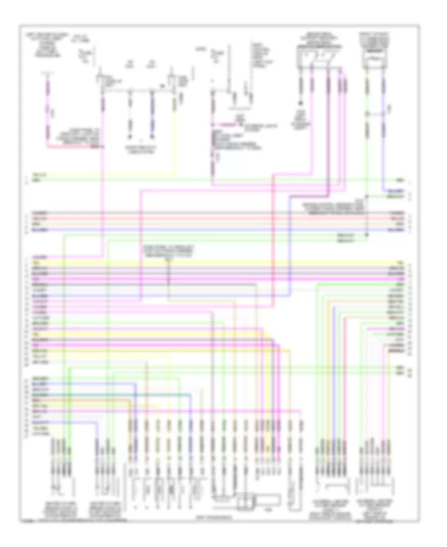
3.5L, Engine Performance Wiring Diagram (3 of 6) for Ford Edge Sport 2014
List of elements for 3.5L, Engine Performance Wiring Diagram (3 of 6) for Ford Edge Sport 2014:
- (dash panel to headlight junction wiring harness, near breakout to anti-lock brake system module) s101
- (throttle body) electronic throttle control (etc) motor
- Battery junction box (bjb) (left side of engine compt)
- C110
- C140
- C175t
- Ce233
- Ce234
- Cet05
- Cet06
- Cet07
- Cet08
- Cet09
- Cet10
- Cet18
- Cet49
- Fuel pump (fp) relay
- Fuse 10a
- Fuse 15a
- Fuse 20a
- Fuse 7.5a
- Ho2s 12
- Ho2s 22
- Hot at all times
- Htr 12
- Htr 22
- Le111
- Lpc
- Oss
- Pcm power relay
- Powertrain control module (pcm) (right rear of engine compt)
- Re406
- Red
- Ret24
- S113
- S117
- Ssa
- Ssb
- Ssc
- Ssd
- Sse
- Tcc
- Tft
- Tft sig rtn
- Tr 1
- Tr 2
- Tr 3
- Tr 4
- Tspc
- Tss
- Tss/oss vpwr
- Tss/oss/tr gnd
- Ve731
- Ve733
- Vet26
- Vet27
- Vet29
- Vet30
- Vet31
- Vet32
- Vet33
3.5L, Engine Performance Wiring Diagram (4 of 6) for Ford Edge Sport 2014
List of elements for 3.5L, Engine Performance Wiring Diagram (4 of 6) for Ford Edge Sport 2014:
- (brake pedal support bracket) brake pedal position (bpp) switch
- (dash panel to headlight junction wiring harness, near breakout to c134) s111
- (dash panel to headlight junction wiring harness, near breakout to c215) s235
- (front of right cylinder bank) cylinder head temperature sensor
- (left center of dash) (w/o intelligent access)
- (not used)
- 6f50 transmission
- Body control module (bcm) (left kick panel)
- C192
- C215
- C2280b
- C2280f
- Cet05
- Cet06
- Cet07
- Cet08
- Cet09
- Cet10
- Cet18
- Cet49
- Computer data lines system
- Exterior lights system
- Fuel pump (fet)
- Fuse 10a
- Fuse 5a
- G105 (left front of engine compt)
- Heated oxygen sensor (ho2s) 12 (in right exhaust, downstream of catalytic converter)
- Heated oxygen sensor (ho2s) 22 (in left exhaust, downstream of catalytic converter)
- Hot at all times
- Hs can +
- Hs can -
- Le111
- Lpc
- Micro
- Nca
- Oss
- Passive anti-theft transceiver
- Pcm wake up (fet)
- Re406
- Ret24
- S127 (engine control sensor & fuel charge wiring harness, near breakout to coil on plug 3)
- Ssa
- Ssb
- Ssc
- Ssd
- Sse
- Tcc
- Tft
- Tft sig rtn
- Tr gnd
- Tr-1
- Tr-2
- Tr-3
- Tr-4
- Trs
- Tspc
- Tss
- Tss/oss gnd
- Tss/oss vpwr
- Universal heated oxygen sensor (ho2s) 11 (right side of engine, on exhaust manifold)
- Universal heated oxygen sensor (ho2s) 21 (left side of engine, on exhaust manifold)
- Vdb04
- Vdb05
- Vet26
- Vet27
- Vet29
- Vet30
- Vet31
- Vet32
- Vet33
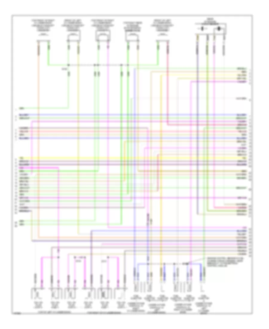
3.5L, Engine Performance Wiring Diagram (5 of 6) for Ford Edge Sport 2014
List of elements for 3.5L, Engine Performance Wiring Diagram (5 of 6) for Ford Edge Sport 2014:
- (engine control sensor & fuel charge wiring harness, near breakout to powertrain control module)
- (front of left cylinder bank) variable camshaft timing (vct) valve 21
- (front of left cylinder bank) variable camshaft timing (vct) valve 22
- (rear of engine) knock sensor
- (top front of right cylinder bank) variable camshaft timing (vct) valve 11
- (top front of right cylinder bank) variable camshaft timing (vct) valve 12
- (top of left cylinder bank)
- (top right of cylinder bank)
- (top right rear of engine) evap emission purge valve
- (under intake manifold, in left cylinder bank)
- (under intake manifold, in right cylinder bank)
- C140
- Coil on plug (cop) 1
- Coil on plug (cop) 2
- Coil on plug (cop) 3
- Coil on plug (cop) 4
- Coil on plug (cop) 5
- Coil on plug (cop) 6
- Fuel injector
- Fuel injector (under intake manifold, in left cylinder bank)
- Fuel injector (under intake manifold, in right cylinder bank)
- S124
- S126
- S128
- S131
- Tan
3.5L, Engine Performance Wiring Diagram (6 of 6) for Ford Edge Sport 2014
List of elements for 3.5L, Engine Performance Wiring Diagram (6 of 6) for Ford Edge Sport 2014:
- (engine control sensor & fuel charge wiring harness, near breakout to crankshaft position sensor)
- (engine control sensor & fuel charge wiring harness, near breakout to powertrain control module)
- (lower left rear of engine) crankshaft position sensor
- (rear of left cylinder bank) camshaft position sensor 21
- (rear of left cylinder bank) camshaft position sensor 22
- (rear of right cylinder bank) camshaft position sensor 11
- (rear of right cylinder bank) camshaft position sensor 12
- Aat
- C175e
- Ce113
- Ce205
- Ce206
- Ce207
- Ce208
- Ce209
- Ce210
- Ce235
- Ce236
- Ce303
- Ce304
- Ce305
- Ce306
- Ce307
- Ce308
- Ce412
- Ce421
- Ce422
- Ce426
- Ce442
- Ce443
- Cht
- Ckp+
- Ckp-
- Cmc24
- Cmp11
- Cmp12
- Cmp21
- Cmp22
- Cop1a
- Cop2c
- Cop3e
- Cop4b
- Cop5d
- Cop6f
- De135
- Etcref
- Etcrtn
- Evapcp
- Inj 1
- Inj 2
- Inj 3
- Inj 4
- Inj 5
- Inj 6
- Instrument cluster system
- Ks1+
- Ks1-
- Ks2+
- Ks2-
- Le134
- Le448
- Le449
- Le450
- Le451
- Le452
- Le453
- Nca
- Oil press
- Powertrain control module (pcm) (right rear of engine compt)
- Re134
- Re135
- Re323
- Re324
- Re405
- Re429
- S125
- S130
- S135
- Shdrtn
- Sigrtn
- Tacm+
- Tacm-
- Tp1
- Tp2
- Uo2s11
- Uo2s21
- Uo2sgref11
- Uo2sgref21
- Uo2shtr11
- Uo2shtr21
- Uo2spc11
- Uo2spc21
- Uo2spct11
- Uo2spct21
- Vct11
- Vct12
- Vct21
- Vct22
- Ve706
- Ve707
- Ve711
- Ve712
- Ve740
- Ve801
- Ve802
- Ve818
- Ve819
- Ve826
- Ve827
- Vrsrtn
- Vrsrtn2
3.7L
3.7L, Engine Performance Wiring Diagram (1 of 6) for Ford Edge Sport 2014
List of elements for 3.7L, Engine Performance Wiring Diagram (1 of 6) for Ford Edge Sport 2014:
- (on battery positive (+) post) generator current sensor
- (top of accelerator pedal) accelerator pedal position (app) sensor
- (under left side of vehicle) evap canister vent valve
- A/c pressure transducer (right front of engine compt)
- Accr
- Acpt
- Air conditioning system
- App1
- App2
- Apprtn
- Apprtn2
- Appvref
- Appvref2
- Awdc
- Awdm
- Battery junction box (bjb) (left side of engine compt)
- Bcs2 alt
- Bpp
- Bps
- C175b
- C212
- C215
- C405
- Canv
- Cbb69
- Cbb90
- Ccb08
- Cdc10
- Cdc12
- Cdc15
- Cdc26
- Cdc35
- Ce114
- Ce237
- Ce436
- Ce608
- Ces09
- Cet42
- Cet43
- Ch302
- Computer data lines system
- Cooling fans system
- Fcv
- Fpc
- Fpm
- Ftp
- Ftpref
- Fuel tank pressure (ftp) sensor (inside fuel tank)
- Fuse 10a
- G109 (on right front shock tower)
- Gd124
- Gen com
- Gen mon
- Hot in run or start
- Hs can +
- Hs can -
- Iat
- Injpwrm
- Isp r
- Kapwr
- Le136
- Le137
- Le230
- Le424
- Maf
- Mafrtn
- Mass air flow/ intake air temperature (maf/iat) sensor (on intake air duct)
- Pcm wake
- Pcmrc
- Powertrain control module (pcm) (right rear of engine compt)
- Pwr gnd
- Re136
- Re137
- Re320
- Re407
- S119 (dash panel to headlight junction wiring harness, near breakout to anti-theft hood switch)
- S120
- S122 (dash panel to headlight junction wiring harness, near breakout to powertrain control module)
- Sbb86
- Sigrtn
- Smc
- Smcs
- Sstd
- Sstu
- Start
- Starting/charging system
- Transmissions system
- Vcf34
- Vcf35
- Vdb04
- Vdb05
- Vdc61
- Ve225
- Ve518
- Ve701
- Ve702
- Ve740
- Ve807
- Ve922
- Vec03
- Vh433
- Vpwr
- Vref
3.7L, Engine Performance Wiring Diagram (2 of 6) for Ford Edge Sport 2014
List of elements for 3.7L, Engine Performance Wiring Diagram (2 of 6) for Ford Edge Sport 2014:
- (base of shift lever assembly) brake shift interlock
- (behind right side of front grille) ambient air temperature sensor
- (if equipped) left paddle shifter
- (if equipped) right paddle shifter
- (main wiring harness, near breakout to accessory protocol interface module)
- (main wiring harness, near breakout to c215) (w/ paddle shift) s240
- (main wiring harness, near breakout to g206)
- (not used)
- (top of steering column) (w/ paddle shift) steering column control module (sccm)
- C140
- C212
- C213
- C218b
- C218c c2414d
- C2414a
- C3053
- C310a
- C405
- Ce515
- Ce608
- Cet42
- Cet43
- Clock spring (steering wheel)
- Computer data lines system
- Cr167
- Ens
- Fpc
- Fpm
- Fppwr
- Fprtn
- Fuel level sensor (awd) (top right side of fuel tank)
- Fuel lvl in 1
- Fuel lvl in 2
- Fuel pump control module (near left side of fuel tank)
- Fuel rtn
- Fuel tank unit
- G205 (right center of dash)
- G405 (top of fuel tank)
- Gd476
- Gnd
- Hs can +
- Hs can -
- Instrument panel cluster (ipc)
- Interior lights system
- Nca
- Pnk
- Re407
- Re515
- Restraints control module (under front of center console)
- S239 (w/ paddle shift)
- S241 (w/ paddle shift)
- S242 (steering wheel jumper wiring harness)
- S243 (steering wheel jumper wiring harness)
- S244
- Sstd
- Sstu
- Transmission control switch
- Ve225
- Ve518
- Vpwr fuel
- W/ select shift
3.7L, Engine Performance Wiring Diagram (3 of 6) for Ford Edge Sport 2014
List of elements for 3.7L, Engine Performance Wiring Diagram (3 of 6) for Ford Edge Sport 2014:
- (dash panel to headlight junction wiring harness, near breakout to anti-lock brake system module) s101
- (throttle body) electronic throttle control (etc) motor
- Battery junction box (bjb) (left side of engine compt)
- C110
- C140
- C175t
- Ce233
- Ce234
- Cet05
- Cet06
- Cet07
- Cet08
- Cet09
- Cet10
- Cet18
- Cet49
- Fuel pump (fp) relay
- Fuse 10a
- Fuse 15a
- Fuse 20a
- Fuse 7.5a
- Ho2s 12
- Ho2s 22
- Hot at all times
- Htr 12
- Htr 22
- Le111
- Lpc
- Oss
- Pcm power relay
- Powertrain control module (pcm) (right rear of engine compt)
- Re406
- Red
- Ret24
- S113
- S117
- Ssa
- Ssb
- Ssc
- Ssd
- Sse
- Tcc
- Tft
- Tft sig rtn
- Tr 1
- Tr 2
- Tr 3
- Tr 4
- Tspc
- Tss
- Tss/oss vpwr
- Tss/oss/tr gnd
- Ve731
- Ve733
- Vet26
- Vet27
- Vet29
- Vet30
- Vet31
- Vet32
- Vet33
3.7L, Engine Performance Wiring Diagram (4 of 6) for Ford Edge Sport 2014
List of elements for 3.7L, Engine Performance Wiring Diagram (4 of 6) for Ford Edge Sport 2014:
- (brake pedal support bracket) brake pedal position (bpp) switch
- (dash panel to headlight junction wiring harness, near breakout to c134) s111
- (dash panel to headlight junction wiring harness, near breakout to c215) s235
- (front of right cylinder bank) cylinder head temperature sensor
- (left center of dash) (w/o intelligent access)
- (not used)
- 6f50 transmission
- Body control module (bcm) (left kick panel)
- C192
- C215
- C2280b
- C2280f
- Cet05
- Cet06
- Cet07
- Cet08
- Cet09
- Cet10
- Cet18
- Cet49
- Computer data lines system
- Exterior lights system
- Fuel pump (fet)
- Fuse 10a
- Fuse 5a
- G105 (left front of engine compt)
- Heated oxygen sensor (ho2s) 12 (in right exhaust, downstream of catalytic converter)
- Heated oxygen sensor (ho2s) 22 (in left exhaust, downstream of catalytic converter)
- Hot at all times
- Hs can +
- Hs can -
- Le111
- Lpc
- Micro
- Nca
- Oss
- Passive anti-theft transceiver
- Pcm wake up (fet)
- Re406
- Ret24
- S127 (engine control sensor & fuel charge wiring harness, near breakout to coil on plug 3)
- Ssa
- Ssb
- Ssc
- Ssd
- Sse
- Tcc
- Tft
- Tft sig rtn
- Tr gnd
- Tr-1
- Tr-2
- Tr-3
- Tr-4
- Trs
- Tspc
- Tss
- Tss/oss gnd
- Tss/oss vpwr
- Universal heated oxygen sensor (ho2s) 11 (right side of engine, on exhaust manifold)
- Universal heated oxygen sensor (ho2s) 21 (left side of engine, on exhaust manifold)
- Vdb04
- Vdb05
- Vet26
- Vet27
- Vet29
- Vet30
- Vet31
- Vet32
- Vet33
3.7L, Engine Performance Wiring Diagram (5 of 6) for Ford Edge Sport 2014
List of elements for 3.7L, Engine Performance Wiring Diagram (5 of 6) for Ford Edge Sport 2014:
- (engine control sensor & fuel charge wiring harness, near breakout to powertrain control module)
- (front of left cylinder bank) variable camshaft timing (vct) valve 21
- (front of left cylinder bank) variable camshaft timing (vct) valve 22
- (rear of engine) knock sensor
- (top front of right cylinder bank) variable camshaft timing (vct) valve 11
- (top front of right cylinder bank) variable camshaft timing (vct) valve 12
- (top of left cylinder bank)
- (top right of cylinder bank)
- (top right rear of engine) evap emission purge valve
- (under intake manifold, in left cylinder bank)
- (under intake manifold, in right cylinder bank)
- C140
- Coil on plug (cop) 1
- Coil on plug (cop) 2
- Coil on plug (cop) 3
- Coil on plug (cop) 4
- Coil on plug (cop) 5
- Coil on plug (cop) 6
- Fuel injector
- Fuel injector (under intake manifold, in left cylinder bank)
- Fuel injector (under intake manifold, in right cylinder bank)
- S124
- S126
- S128
- S131
- Tan
3.7L, Engine Performance Wiring Diagram (6 of 6) for Ford Edge Sport 2014
List of elements for 3.7L, Engine Performance Wiring Diagram (6 of 6) for Ford Edge Sport 2014:
- (engine control sensor & fuel charge wiring harness, near breakout to crankshaft position sensor)
- (engine control sensor & fuel charge wiring harness, near breakout to powertrain control module)
- (lower left rear of engine) crankshaft position sensor
- (rear of left cylinder bank) camshaft position sensor 21
- (rear of left cylinder bank) camshaft position sensor 22
- (rear of right cylinder bank) camshaft position sensor 11
- (rear of right cylinder bank) camshaft position sensor 12
- Aat
- C175e
- Ce113
- Ce205
- Ce206
- Ce207
- Ce208
- Ce209
- Ce210
- Ce235
- Ce236
- Ce303
- Ce304
- Ce305
- Ce306
- Ce307
- Ce308
- Ce412
- Ce421
- Ce422
- Ce426
- Ce442
- Ce443
- Cht
- Ckp+
- Ckp-
- Cmc24
- Cmp11
- Cmp12
- Cmp21
- Cmp22
- Cop1a
- Cop2c
- Cop3e
- Cop4b
- Cop5d
- Cop6f
- De135
- Etcref
- Etcrtn
- Evapcp
- Inj 1
- Inj 2
- Inj 3
- Inj 4
- Inj 5
- Inj 6
- Instrument cluster system
- Ks1+
- Ks1-
- Ks2+
- Ks2-
- Le134
- Le448
- Le449
- Le450
- Le451
- Le452
- Le453
- Nca
- Oil press
- Powertrain control module (pcm) (right rear of engine compt)
- Re134
- Re135
- Re323
- Re324
- Re405
- Re429
- S125
- S130
- S135
- Shdrtn
- Sigrtn
- Tacm+
- Tacm-
- Tp1
- Tp2
- Uo2s11
- Uo2s21
- Uo2sgref11
- Uo2sgref21
- Uo2shtr11
- Uo2shtr21
- Uo2spc11
- Uo2spc21
- Uo2spct11
- Uo2spct21
- Vct11
- Vct12
- Vct21
- Vct22
- Ve706
- Ve707
- Ve711
- Ve712
- Ve740
- Ve801
- Ve802
- Ve818
- Ve819
- Ve826
- Ve827
- Vrsrtn
- Vrsrtn2