ENGINE PERFORMANCE
1.8L
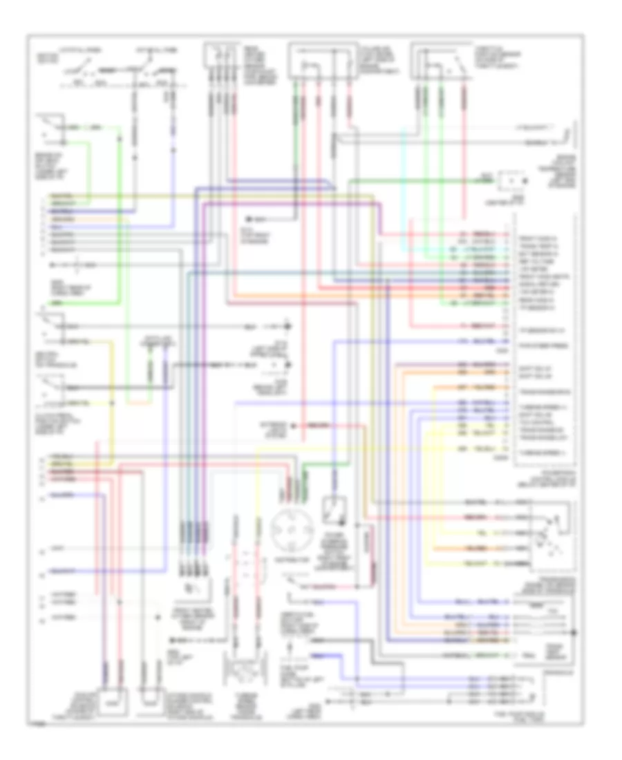
1.8L, Engine Performance Wiring Diagrams (1 of 2) for Ford Escort 1996

List of elements for 1.8L, Engine Performance Wiring Diagrams (1 of 2) for Ford Escort 1996:
- a/c on in
- a/c relay out
- blwr mtr on
- brake sw in
- coolng fan on
- crank pos in
- dist ign module
- distributor
- drl in
- fprv sol ctrl
- ground
- mil output
- neutral sw
- power (b+)
- rear defog in
- vss (+)
- vss (-)
- (a/t only)
- (m/t only)
- Air conditioning system
- C111
- C204
- C205
- C210
- C220
- C227
- C240
- Cooling fans system
- Crank pos sens
- Crankshaft position sensor (right end of engine)
- Cruise control system
- Data link connector 1
- Defogger system
- Distributor ignition (di) module (left side of engine comp't)
- Dlc #2 conn
- Dlc conn
- Engine compartment fuse box
- Engine fuse 15a
- Evap can purge
- Evaporative emission canister purge valve (center of safety wall)
- Exterior lights system
- Fuel inj 30a
- Fuel injectors
- Fuel pressure regulator vacuum solenoid (right end of intake manifold)
- Fuel pump 20a
- Fuel pump relay (under center of i/p)
- Fuel pump rly
- G110 (top left front of engine)
- G112 (top left side of engine)
- G116 (left side of safety wall)
- G206 (center of i/p)
- Ground
- Headlights system
- Hot at all times
- Hot in run or start
- Hot in start
- I/p fuse panel
- Iac control
- Ignition coil (left side of engine comp't)
- Ignition pwr
- Imr sol ctrl
- Inj #1 ctrl
- Inj #2 ctrl
- Inj #3 ctrl
- Inj #4 ctrl
- Instrument cluster system
- Meter fuse 15a
- Nca
- Obd ii fuse 10a
- Park lmp rly
- Pcm power relay
- Powertrain control module (below center of i/p)
- Radio noise capacitor (on distributor ignition module)
- Room fuse 15a
- Start sig
- Start sig in
- Start signal 10a
- Stop fuse 20a
- To distributor
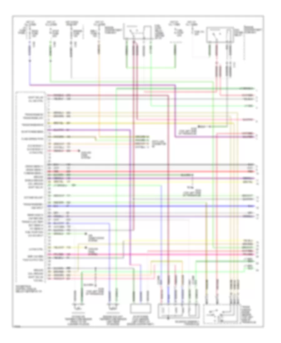
1.8L, Engine Performance Wiring Diagrams (2 of 2) for Ford Escort 1996
List of elements for 1.8L, Engine Performance Wiring Diagrams (2 of 2) for Ford Escort 1996:
- Acc
- Brake on/ off (boo) switch (under left side of i/p)
- C2009
- C238
- Clutch pedal position switch (under left side of i/p)
- Data link connector 2
- Distributor
- Ect sensor in
- Engine coolant temperature sensor (left end of engine)
- Exterior lights system
- Front heated oxygen sensor (front of engine)
- Front ho2s heatr
- Front ho2s in
- Fuel pump diode (bottom of left 'b' pillar)
- Fuel pump module (fuel tank)
- G106 (behind left headlight)
- G110 (top front of engine)
- G116 (left side of safety wall)
- G202 (top left of i/p)
- G206 (center of i/p)
- G402 (left rear cargo area)
- G405 (right rear of cargo area
- Hot at all times
- Hot at all times ignition switch
- Idle air control solenoid (on side of throttle body)
- Inertia fuel shutoff (right side of cargo area)
- Intake manifold runner control solenoid (right end of intake manifold)
- Lock
- Nca
- Neutral switch (on transaxle)
- Power steering pressure switch (right front of engine compartment)
- Powertrain control module (below center of i/p)
- Pwr steer press
- Rear heated oxygen sensor (in exhaust pipe, behind converter)
- Rear ho2s in
- Red
- Ref voltage
- Run
- Shift sol #1
- Shift sol #2
- Shift sol #3
- Signal return
- Start
- Tcc
- Tcc control
- Throttle position sensor (on side of throttle body)
- Tp sensor in
- Tp sensor sw in
- Trans range-drve
- Trans range-low
- Trans range-od
- Trans temp in
- Trans temp sensor
- Transaxle
- Transmission range (tr) sensor (side of transaxle)
- Turbine speed (+)
- Turbine speed (-)
- Turbine speed sensor (inside transaxle)
- Vaf meter
- Vaf meter in
- Volume air flow meter (left side of engine compartment)
1.9L
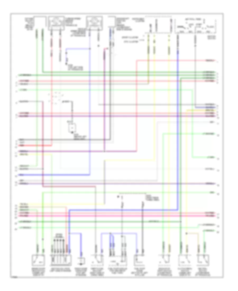
1.9L, Engine Performance Wiring Diagrams (1 of 3) for Ford Escort 1996
List of elements for 1.9L, Engine Performance Wiring Diagrams (1 of 3) for Ford Escort 1996:
- A/c on input
- Air conditioning system
- C111
- C210
- C240
- Coil ground
- Cooling fans system
- Crank sens (+)
- Crank sens (-)
- Data link connector #2
- Dlc #2 bus (+)
- Dlc #2 bus (-)
- Ect sens in
- Egr vac reg
- Engine compartment fuse box
- Engine coolant temperature sensor (left rear of engine)
- Engine fuse 15a
- Evap purge flow sensor (left front of engine compartment)
- Evap purge sens
- Flash eprom pwr
- Fuel inj 30a
- Fuel pump 20a
- Fuel pump mon
- Fuel pump relay (under center of i/p)
- G129 (top left side of transaxle)
- Ground
- Hi fan ctrl
- Hot at all times
- Hot in run or start
- I/p fuse panel
- Iat sens in
- Intake air temperature sensor (front of air cleaner housing)
- Lo fan ctrl
- Maf return
- Mil ind ctrl
- Nca
- Obd ii fuse 10a
- Octane adjust
- Pcm power relay
- Powertrain control module (below center of i/p)
- Rear ho2s in
- Red
- Room fuse 15a
- Shield ground
- Shift sol #1
- Shift sol #2
- Shift sol #3
- Solenoid assembly (transaxle)
- Stop fuse 20a
- Tach output sig
- Tcc sol
- Trans fluid temp
- Trans rnge-drve
- Trans rnge-low
- Trans rnge-od
- Trans rnge-rev
- Trans- mission range sensor (top left side of transaxle)
- Turbine sens (-)
- Vss input
1.9L, Engine Performance Wiring Diagrams (2 of 3) for Ford Escort 1996
List of elements for 1.9L, Engine Performance Wiring Diagrams (2 of 3) for Ford Escort 1996:
- (a/t only)
- Acc
- Backup/up- shift switch (lower front of transaxle)
- Brake on/off (boo) switch (under left side of i/p)
- Clutch pedal switch (under left side of i/p)
- Crankshaft position (ckp) sensor (lower right side of engine)
- Fuel pump diode (bottom of left 'b' pillar)
- Fuel pump module (top center of fuel tank)
- G106 (behind left headlight)
- G129 (top left side of transaxle)
- G402 (right rear cargo area)
- Hot at all times
- Ignition coil pack (left side of engine)
- Ignition switch
- Inertia fuel shutoff (right side of cargo area)
- Instrument cluster
- Lock
- Mil lamp
- N/a
- Nca
- Neutral switch (lower rear of transaxle)
- Octane adjust plug (below center of i/p)
- Radio noise capacitor (top left of engine)
- Red
- Run
- Spark plugs
- Sport cluster
- Start
- Std. cluster
- Tachometer
- Turbine speed sensor (top of transaxle)
- Upshift lamp
- Vehicle speed sensor (lower rear of transaxle)
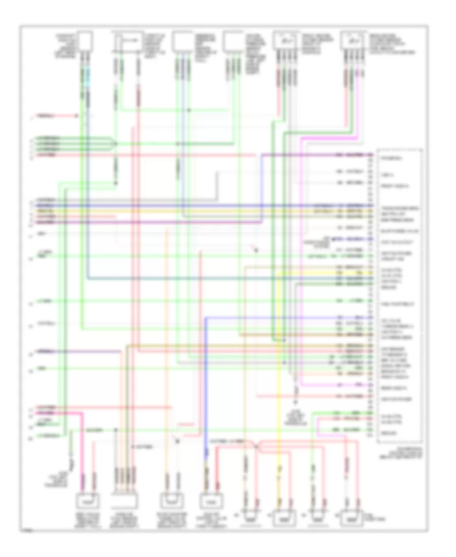
1.9L, Engine Performance Wiring Diagrams (3 of 3) for Ford Escort 1996
List of elements for 1.9L, Engine Performance Wiring Diagrams (3 of 3) for Ford Escort 1996:
- (a/t only)
- (m/t only)
- A/c press sens
- Air con- ditioning pressure sensor (on a/c pressure line, left side of engine comp't)
- Air conditioning system
- Brake sw in
- Cam pos (+)
- Cam pos (-)
- Camshaft position (cmp) sensor (left rear of engine)
- Egr press sens
- Egr vacuum regulator (center of safety wall)
- Evap canister purge valve (left front of engine comp't)
- Evap purge valve
- Feedback pressure egr sensor (center of safety wall)
- Front heated oxygen sensor (front of engine in manifold)
- Front ho2s in
- Fuel injectors
- Fuel pump relay
- G129 (top left side of transaxle)
- Ground
- Iac valve
- Idle air control valve (top of throttle body)
- Ignition power
- Inj #1 ctrl
- Inj #2 ctrl
- Inj #3 ctrl
- Inj #4 ctrl
- Maf sensor
- Mass air flow sensor (left side of engine comp't)
- Nca
- Neutral sw
- Power b(+)
- Powertrain control module (below center of i/p)
- Rear heated oxygen sensor (in exhaust down pipe, behind catalytic converter)
- Rear ho2s in
- Red
- Ref voltage
- Signal return
- Tan
- Throttle position sensor (side of throttle body)
- Tp sensor in
- Trans range sens
- Turbine sens (+)
- Upshift ind
- Vss (+)
- Wot a/c cutout