ENGINE PERFORMANCE
4.6L
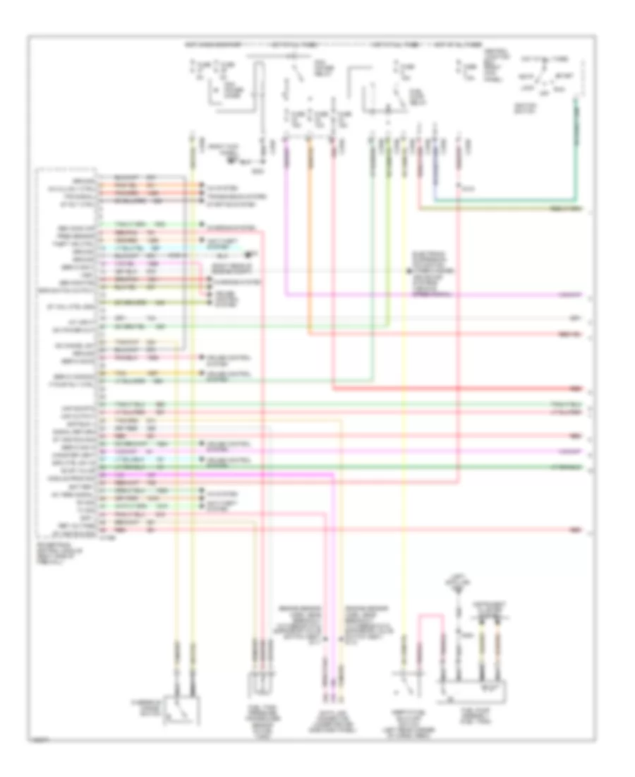
4.6L, Engine Performance Wiring Diagram (1 of 4) for Ford Expedition 2004

List of elements for 4.6L, Engine Performance Wiring Diagram (1 of 4) for Ford Expedition 2004:
- (engine sensor harn, near breakout to therostatic expansion valve switch assy) s110
- (engine sensor harn, near breakout to therostatic expansion valve switch assy) s111
- (left b-pillar) g300
- (right rear of engine compt)
- A/c clu rly ctrl
- A/c system
- Ac term signal
- Acc
- Anti-theft system
- Battery
- Bps switch output
- C175b
- C270a
- C270b
- C270d
- C270f
- C270g
- C270k
- Canister vent
- Central junction box (right kick panel)
- Charging system
- Cruise control system
- Data link connector (under driver side dash panel)
- Electronic suspension, navigation, wiper/washer, and sound systems (vehicle speed signal)
- Evap valve
- F pump rly ctrl
- Fuel pump assembly (fuel tank)
- Fuel pump relay
- Fuel tank pressure transducer sensor (in fuel tank)
- Fuse
- Fuse 10a
- Fuse 15a
- Fuse 7.5a
- G102
- Gen comm cir
- Gen monitor
- Ground
- Hot at all times
- Hot in run or start
- Iat input
- Ignition switch
- Inertia fuel shut-off switch (left rear corner of cargo area)
- Instrument cluster system
- Lock
- Maf output
- Maf sig rtn
- Module prog sig
- Nca
- Od cancel sw
- Off
- Overdrive cancel switch
- Pcm power diode
- Pcm power relay
- Powertrain control module (right side of firewall)
- Pres sensor
- Red
- Red/pnk
- Ref voltage
- Run
- Rx sig
- S108
- S133
- S203
- S454
- Scp -
- Scp bus +
- Servo common
- Servo sig a
- Servo sig b
- Servo sig c
- Signal return
- Spd ctrl sw in
- St and run sig
- St rly ctrl
- St whl ctrl gnd
- Start
- Starting system
- Sw power out
- Tan
- Theft ind ctrl
- Tps signal
- Transmission system
- Tx sig
- Vss+
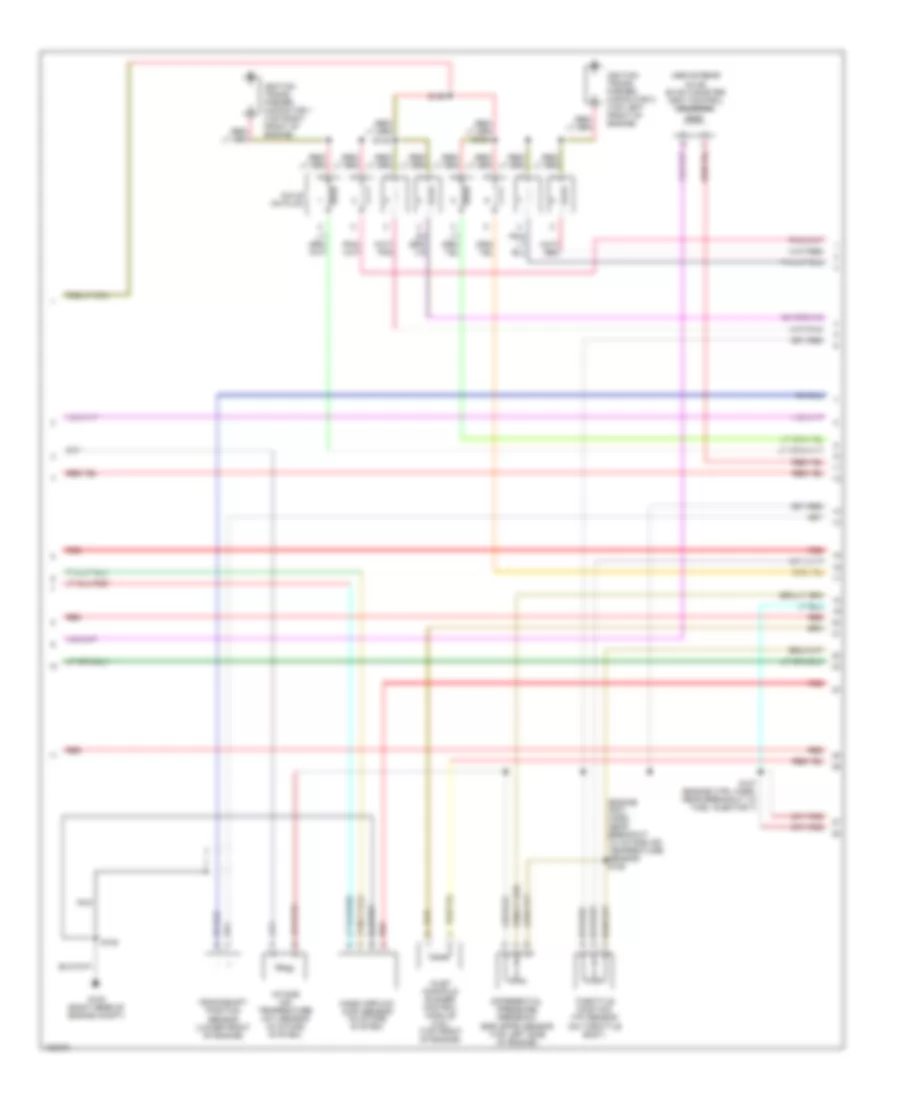
4.6L, Engine Performance Wiring Diagram (2 of 4) for Ford Expedition 2004
List of elements for 4.6L, Engine Performance Wiring Diagram (2 of 4) for Ford Expedition 2004:
- (above rear axle) evap canister vent control solenoid
- (engine crtl harn, near breakout to intake air temperature sensor) s125
- Coils on plug
- Crankshaft position sensor (lower front of engine)
- Differential pressure feedback egr (dpfe) sensor (top left side of engine)
- G102 (right rear of engine compt)
- Ignition trans- former capacitor 1 (top right front of engine)
- Ignition trans- former capacitor 2 (top left front of engine)
- Inlet manifold runner control module (4.6l) (top front of engine)
- Intake air temperature (iat) sensor (in intake system)
- Mass airflow (maf) sensor (in intake system)
- Nca
- Red
- S108
- S124
- S127 (engine ctrl harn, near breakout to fuel injector 7)
- S129
- S132
- Throttle position (tp) sensor (on throttle body)
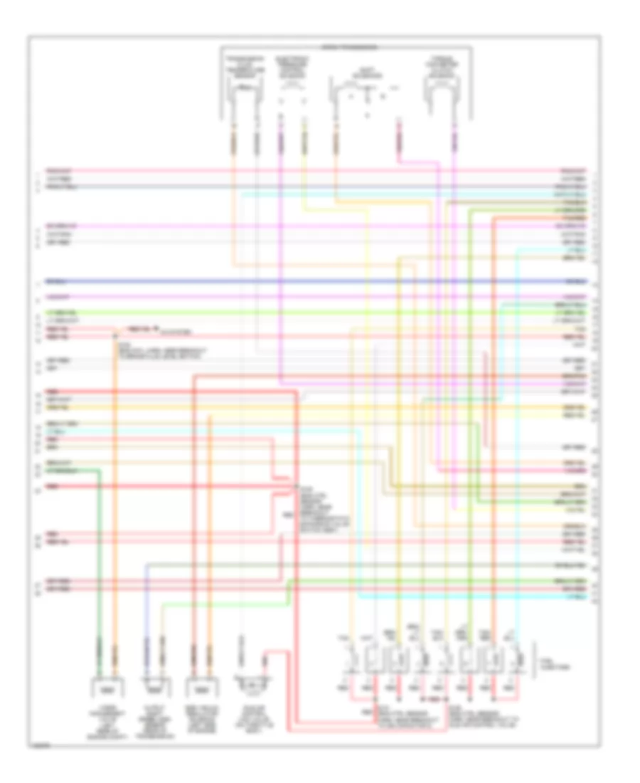
4.6L, Engine Performance Wiring Diagram (3 of 4) for Ford Expedition 2004
List of elements for 4.6L, Engine Performance Wiring Diagram (3 of 4) for Ford Expedition 2004:
- (left rear of engine compt)
- 4r70w transmission
- A/c system
- Egr vacuum regulator solenoid (left side of engine)
- Electronic pressure control solenoid
- Fuel injectors
- Idle air control (iac) valve (on throttle body)
- Output shaft speed (oss) sensor (rear of transmission)
- Red
- S105 (eng cntl harn, near breakout to brake fluid level switch)
- S109 (eng ctrl sensor harn, near breakout to thermostatic expansion valve switch assy)
- S126 (eng ctrl sensor harn, near breakout to idle air control valve)
- S131 (eng ctrl sensor harn, near breakout to ign capacitor 2)
- Shift solenoids
- Tan
- Tan/ red
- Tan/red
- Torque converter clutch solenoid
- Transmission fluid temperature sensor
- Vapor management valve
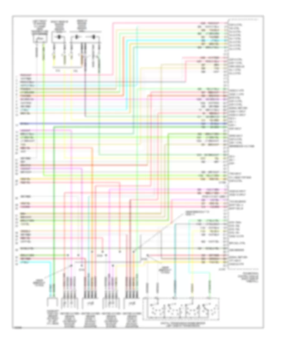
4.6L, Engine Performance Wiring Diagram (4 of 4) for Ford Expedition 2004
List of elements for 4.6L, Engine Performance Wiring Diagram (4 of 4) for Ford Expedition 2004:
- (left front of engine) cylinder head temperature (cht) sensor
- (near breakout to h02s 11)
- (near breakout to pcm)
- (pins 4-10 not used)
- (rear of engine) knock sensor (4.6l)
- (right rear of engine) knock sensor (5.4l)
- 4.6l
- 5.4l
- C175e
- C175t
- Camshaft position sensor (on front of left cyl head)
- Ckp +
- Ckp -
- Cmp input
- Cop 1 ctrl
- Cop 2 ctrl
- Cop 3 ctrl
- Cop 4 ctrl
- Cop 5 ctrl
- Cop 6 ctrl
- Cop 7 ctrl
- Cop 8 ctrl
- Cyl head tmp sns
- Digital transmission range sensor (left side of transmission)
- Dpfe input
- Dtr, tr1
- Dtr, tr2
- Dtr, tr3a
- Dtr, tr4
- Early production
- Epc sol ctrl
- Evr ctrl
- Heated oxygen sensor (ho2s) 11 (on right exhaust downpipe)
- Heated oxygen sensor (ho2s) 12 (on rear of exhaust system)
- Heated oxygen sensor (ho2s) 21 (on left exhaust downpipe)
- Heated oxygen sensor (ho2s) 22 (on rear of exhaust system)
- Ho2s 11 htr
- Ho2s 11 input
- Ho2s 12 htr
- Ho2s 12 input
- Ho2s 21 htr
- Ho2s 21 input
- Ho2s 22 htr
- Ho2s 22 input
- Iac ctrl
- Imrc module
- Inj 1 ctrl
- Inj 2 ctrl
- Inj 3 ctrl
- Inj 4 ctrl
- Inj 5 ctrl
- Inj 6 ctrl
- Inj 7 ctrl
- Inj 8 ctrl
- Ks 1 +
- Ks 1 -
- Ks 2 +
- Ks 2 -
- Nca
- Oss sensor
- Powertrain control module (right side of firewall)
- R n
- Reference voltage
- S128
- S138
- S140
- Shift sol a
- Shift sol b
- Signal return
- Tan
- Tan/red
- Tcc solenoid
- Tft input
- Tps input
5.4L
5.4L, Engine Performance Wiring Diagram (1 of 4) for Ford Expedition 2004
List of elements for 5.4L, Engine Performance Wiring Diagram (1 of 4) for Ford Expedition 2004:
- (engine sensor harn, near breakout to therostatic expansion valve switch assy) s110
- (engine sensor harn, near breakout to therostatic expansion valve switch assy) s111
- (left b-pillar) g300
- (right rear of engine compt)
- A/c clu rly ctrl
- A/c system
- Ac term signal
- Acc
- Anti-theft system
- Battery
- Bps switch output
- C175b
- C270a
- C270b
- C270d
- C270f
- C270g
- C270k
- Canister vent
- Central junction box (right kick panel)
- Charging system
- Cruise control system
- Data link connector (under driver side dash panel)
- Electronic suspension, navigation, wiper/washer, and sound systems (vehicle speed signal)
- Evap valve
- F pump rly ctrl
- Fuel pump assembly (fuel tank)
- Fuel pump relay
- Fuel tank pressure transducer sensor (in fuel tank)
- Fuse
- Fuse 10a
- Fuse 15a
- Fuse 7.5a
- G102
- Gen comm cir
- Gen monitor
- Ground
- Hot at all times
- Hot in run or start
- Iat input
- Ignition switch
- Inertia fuel shut-off switch (left rear corner of cargo area)
- Instrument cluster system
- Lock
- Maf output
- Maf sig rtn
- Module prog sig
- Nca
- Od cancel sw
- Off
- Overdrive cancel switch
- Pcm power diode
- Pcm power relay
- Powertrain control module (right side of firewall)
- Pres sensor
- Red
- Red/pnk
- Ref voltage
- Run
- Rx sig
- S108
- S133
- S203
- S454
- Scp -
- Scp bus +
- Servo common
- Servo sig a
- Servo sig b
- Servo sig c
- Signal return
- Spd ctrl sw in
- St and run sig
- St rly ctrl
- St whl ctrl gnd
- Start
- Starting system
- Sw power out
- Tan
- Theft ind ctrl
- Tps signal
- Transmission system
- Tx sig
- Vss+
5.4L, Engine Performance Wiring Diagram (2 of 4) for Ford Expedition 2004
List of elements for 5.4L, Engine Performance Wiring Diagram (2 of 4) for Ford Expedition 2004:
- (above rear axle) evap canister vent control solenoid
- (engine crtl harn, near breakout to intake air temperature sensor) s125
- Coils on plug
- Crankshaft position sensor (lower front of engine)
- Differential pressure feedback egr (dpfe) sensor (top left side of engine)
- G102 (right rear of engine compt)
- Ignition trans- former capacitor 1 (top right front of engine)
- Ignition trans- former capacitor 2 (top left front of engine)
- Inlet manifold runner control module (4.6l) (top front of engine)
- Intake air temperature (iat) sensor (in intake system)
- Mass airflow (maf) sensor (in intake system)
- Nca
- Red
- S108
- S124
- S127 (engine ctrl harn, near breakout to fuel injector 7)
- S129
- S132
- Throttle position (tp) sensor (on throttle body)
5.4L, Engine Performance Wiring Diagram (3 of 4) for Ford Expedition 2004
List of elements for 5.4L, Engine Performance Wiring Diagram (3 of 4) for Ford Expedition 2004:
- (left rear of engine compt)
- 4r70w transmission
- A/c system
- Egr vacuum regulator solenoid (left side of engine)
- Electronic pressure control solenoid
- Fuel injectors
- Idle air control (iac) valve (on throttle body)
- Output shaft speed (oss) sensor (rear of transmission)
- Red
- S105 (eng cntl harn, near breakout to brake fluid level switch)
- S109 (eng ctrl sensor harn, near breakout to thermostatic expansion valve switch assy)
- S126 (eng ctrl sensor harn, near breakout to idle air control valve)
- S131 (eng ctrl sensor harn, near breakout to ign capacitor 2)
- Shift solenoids
- Tan
- Tan/ red
- Tan/red
- Torque converter clutch solenoid
- Transmission fluid temperature sensor
- Vapor management valve
5.4L, Engine Performance Wiring Diagram (4 of 4) for Ford Expedition 2004
List of elements for 5.4L, Engine Performance Wiring Diagram (4 of 4) for Ford Expedition 2004:
- (left front of engine) cylinder head temperature (cht) sensor
- (near breakout to h02s 11)
- (near breakout to pcm)
- (pins 4-10 not used)
- (rear of engine) knock sensor (4.6l)
- (right rear of engine) knock sensor (5.4l)
- 4.6l
- 5.4l
- C175e
- C175t
- Camshaft position sensor (on front of left cyl head)
- Ckp +
- Ckp -
- Cmp input
- Cop 1 ctrl
- Cop 2 ctrl
- Cop 3 ctrl
- Cop 4 ctrl
- Cop 5 ctrl
- Cop 6 ctrl
- Cop 7 ctrl
- Cop 8 ctrl
- Cyl head tmp sns
- Digital transmission range sensor (left side of transmission)
- Dpfe input
- Dtr, tr1
- Dtr, tr2
- Dtr, tr3a
- Dtr, tr4
- Early production
- Epc sol ctrl
- Evr ctrl
- Heated oxygen sensor (ho2s) 11 (on right exhaust downpipe)
- Heated oxygen sensor (ho2s) 12 (on rear of exhaust system)
- Heated oxygen sensor (ho2s) 21 (on left exhaust downpipe)
- Heated oxygen sensor (ho2s) 22 (on rear of exhaust system)
- Ho2s 11 htr
- Ho2s 11 input
- Ho2s 12 htr
- Ho2s 12 input
- Ho2s 21 htr
- Ho2s 21 input
- Ho2s 22 htr
- Ho2s 22 input
- Iac ctrl
- Imrc module
- Inj 1 ctrl
- Inj 2 ctrl
- Inj 3 ctrl
- Inj 4 ctrl
- Inj 5 ctrl
- Inj 6 ctrl
- Inj 7 ctrl
- Inj 8 ctrl
- Ks 1 +
- Ks 1 -
- Ks 2 +
- Ks 2 -
- Nca
- Oss sensor
- Powertrain control module (right side of firewall)
- R n
- Reference voltage
- S128
- S138
- S140
- Shift sol a
- Shift sol b
- Signal return
- Tan
- Tan/red
- Tcc solenoid
- Tft input
- Tps input