ENGINE PERFORMANCE
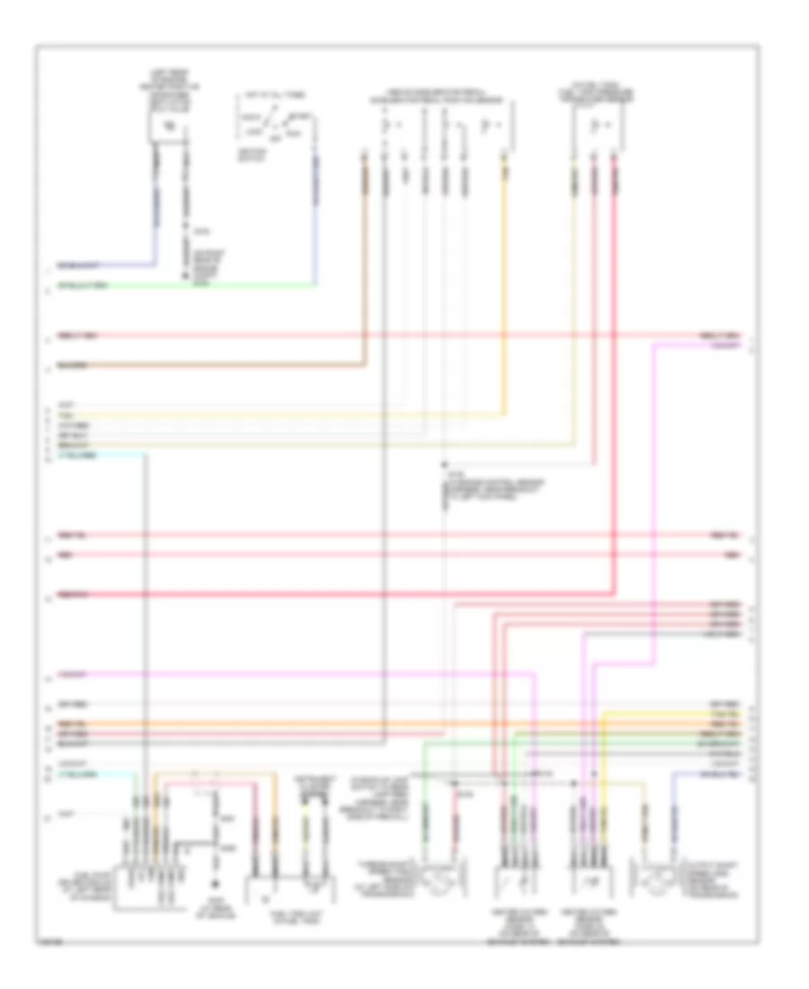
Engine Performance Wiring Diagram (1 of 5) for Ford Expedition 2006

List of elements for Engine Performance Wiring Diagram (1 of 5) for Ford Expedition 2006:
- (in engine control sensor harness, near breakout to g102)
- (in engine control sensor harness, near breakout to g102) s109
- (in engine control sensor harness, near breakout to left side of engine compt) s147
- (on right rear of engine compartment)
- (w/ four wheel drive) s152
- 4wd sw pos sns
- 4wd sw sig rtn
- A/c clu rly ctrl
- Air bag sig
- Air conditioning system
- Air suspension module (under left side of dash)
- Alternator
- Alternator monitor
- Anti-theft ind
- Anti-theft system
- App sensor power
- App sensor return
- App sensor sig 1
- App sensor sig 2
- App sensor sig 3
- Bpp sw signal
- C175b
- C2324a
- C240a
- C270a
- C270b
- C270d
- C270e
- C270f
- C270g
- C270k
- Canister vent
- Central junction box (cjb) (behind right kick panel)
- Cruise control system
- Data link connector (dlc) (under left side of dash)
- Deactivator sw sig
- Exterior lights system
- Fpm monitor
- Fuel pump ctrl
- Fuel pump relay
- Fuel tank sensor
- Fuse
- Fuse 15a
- Fuse 25a
- Fuse 5a
- Fuse 7.5a
- G101 (near right side of radiator)
- G102
- G102 (on right rear of engine compartment)
- Ground
- Heated positive crankcase ventilation (pcv) valve relay
- High speed can +
- High speed can -
- Hot at all times
- Hot in run or start
- Iat sensor sig
- Inertia fuel shutoff (ifs) switch (left rear corner of cargo area, behind trim)
- Kick panel) g200
- Maf sensor sig
- Maf sns sig rtn
- Mass air flow/intake air temperature (maf/iat) sensor (in intake system)
- Module program
- Nca
- Overdrive cancel switch
- Overdrive sw
- Pcm power diode
- Pcm power relay
- Powertrain control module (pcm) (on right side of firewall)
- Pressure switch
- Radio
- Red
- Red/pnk
- Reference volt
- Rx signal
- S107
- S108
- S116
- S133
- S146 (in engine control sensor harness, near breakout to left side of engine compt)
- S153
- S203
- Sig return
- Solenoid ctrl
- Speed ctrl sw
- Starter relay
- Starting/charging system
- Steering wheel
- Tan
- Transfer case rly
- Transmissions system
- Tx signal
- Vbatt
- Vehicle speed sig
- Vpwr
- Vss
- Windshield wiper motor (on left side of firewall)
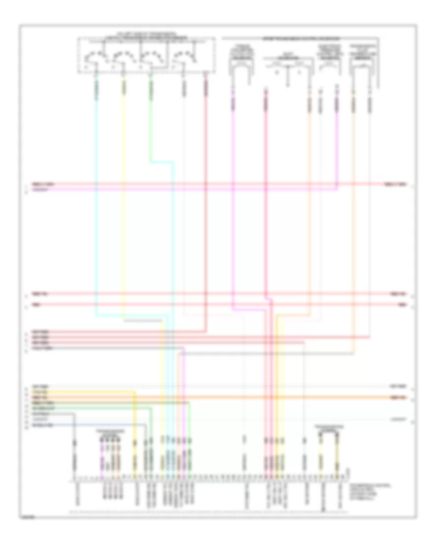
Engine Performance Wiring Diagram (2 of 5) for Ford Expedition 2006
List of elements for Engine Performance Wiring Diagram (2 of 5) for Ford Expedition 2006:
- (above accelerator pedal) accelerator pedal position sensor
- (in back-up lamp switch to rear lamp feed harness, near breakout to right side of firewall)
- (in fuel tank) fuel tank pressure transducer sensor
- (left rear of engine) heated positive crankcase ventilation (pcv) valve
- (on right rear of engine compt) g102
- Acc
- Fuel pump driver module (at left rear of chassis)
- Fuel tank unit (in fuel tank)
- G403 (at rear of vehicle)
- Gnd
- Heated oxygen sensor (ho2s) 12 (on rear of exhaust system)
- Heated oxygen sensor (ho2s) 22 (on rear of exhaust system)
- Hot at all times
- Ignition switch
- Instrument cluster system
- Lock
- Nca
- Off
- Output shaft speed (oss) sensor (on rear of transmission)
- Red
- Red/pnk
- Run
- S138
- S140
- S153
- S459
- S461
- Start
- Tan
- Turbine shaft speed (tss) sensor (at left side of transmission)
Engine Performance Wiring Diagram (3 of 5) for Ford Expedition 2006
List of elements for Engine Performance Wiring Diagram (3 of 5) for Ford Expedition 2006:
- (on left side of transmission) digital transmission range (dtr) sensor
- 4r75e transmission control solenoids
- C175t
- Diff lock sol
- Dtr sens tr4
- Electronic pressure control (epc) solenoid
- Epc sol ctrl
- Ho2s 12 htr
- Ho2s 12 sig
- Ho2s 22 htr
- Ho2s 22 sig
- Motor a
- Motor b
- Motor c
- Motor d
- Motor return
- N r
- Of firewall)
- Oss sens sig
- Powertrain control module (pcm) (on right side
- Red
- Sensor tr1
- Sensor tr2
- Sensor tr3a
- Shift sol a
- Shift sol b
- Shift solenoids
- Sig return
- Tcc sol ctrl
- Tft sens sig
- Torque converter clutch (tcc) solenoid
- Transmission fluid temperature sensor
- Transmissions system
- Tss sens sig
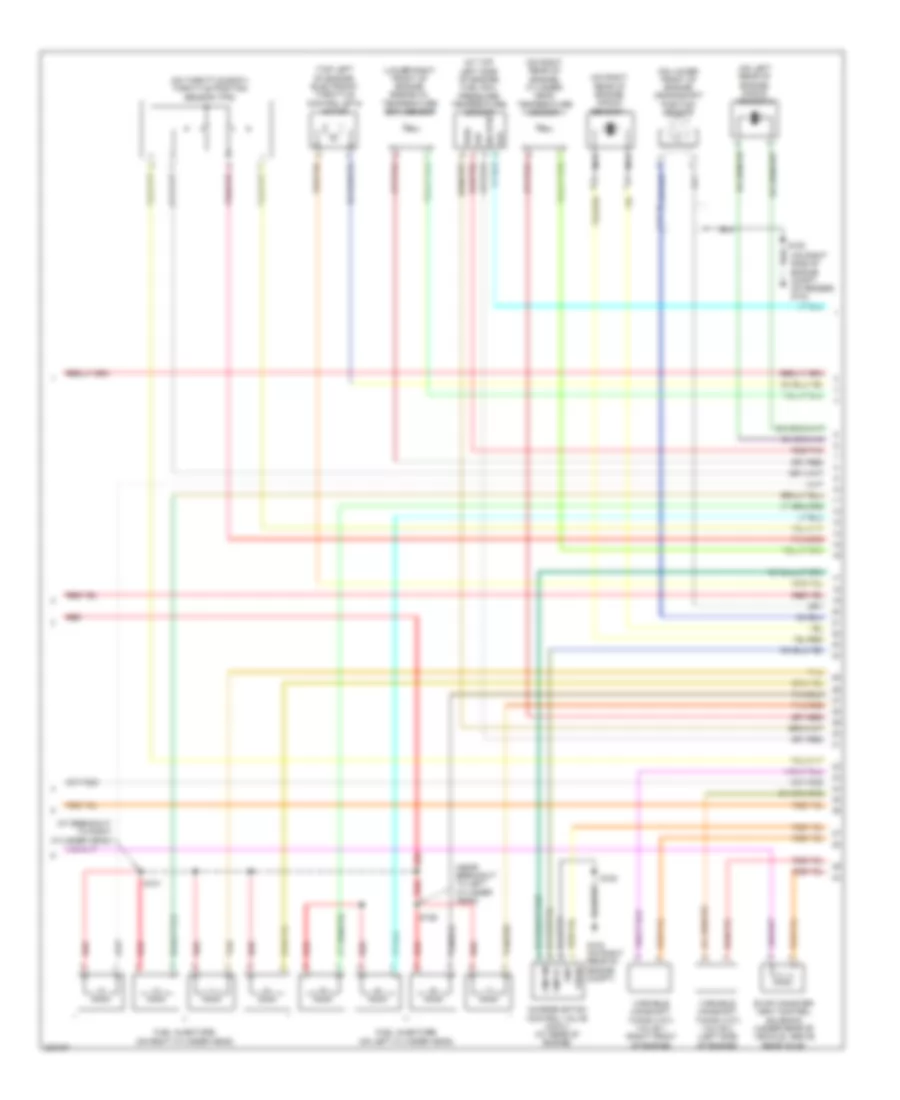
Engine Performance Wiring Diagram (4 of 5) for Ford Expedition 2006
List of elements for Engine Performance Wiring Diagram (4 of 5) for Ford Expedition 2006:
- (at breakout to right cylinder head)
- (at top left side of engine) fuel rail pressure/ temperature sensor
- (lower right front of engine) engine oil temperature (eot) sensor
- (near breakout to left cylinder head)
- (on left rear of engine) knock sensor 2
- (on lower front of engine) crankshaft position sensor
- (on right rear of engine) cylinder head temperature sensor
- (on right rear of engine) knock sensor 1
- (on right side of engine compt, on fender) g103
- (on throttle body) throttle position sensor (tps)
- (top left of engine) electronic throttle control (etc) motor
- Charge motion control valve (cmcv) (at rear of engine)
- Cmcvc
- Cmcvm
- Evap canister vent control solenoid (under rear of vehicle, above rear axle)
- Frp
- Fuel injectors (on left cylinder head)
- Fuel injectors (on right cylinder head)
- G102 (on right rear of engine compt)
- Gnd
- Nca
- Prt
- Red
- Red/pnk
- S126
- S131
- S153
- Sig rtn
- Tan
- Tan/red
- Variable camshaft timing (vct) valve 1 (right front of engine)
- Variable camshaft timing (vct) valve 2 (left side of engine)
- Vpwr
- Vref
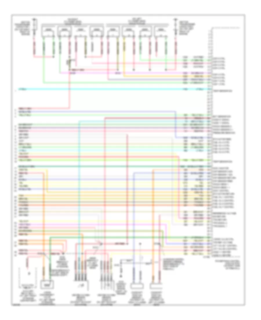
Engine Performance Wiring Diagram (5 of 5) for Ford Expedition 2006
List of elements for Engine Performance Wiring Diagram (5 of 5) for Ford Expedition 2006:
- (in engine control sensor harness, near breakout to right side of firewall)
- (near breakout to left cylinder head)
- (on left cylinder head) coils on plug
- (on right cylinder head) coils on plug
- A/c clutch relay
- Auxiliary relay box 1 (at left front of engine compartment)
- C175e
- Camshaft position sensor 1 (on front of right cylinder bank)
- Camshaft position sensor 2 (on front of left cylinder head)
- Ckp sensor feed
- Ckp sensor return
- Cmcv control
- Cmcv monitor
- Cmp sensor 1 sig
- Cmp sensor 2 sig
- Cop 1 ctrl
- Cop 2 ctrl
- Cop 3 ctrl
- Cop 4 ctrl
- Cop 5 ctrl
- Cop 6 ctrl
- Cop 7 ctrl
- Cop 8 ctrl
- Eot sensor sig
- Etc motor feed
- Etc motor return
- Fuel inj 1 control
- Fuel inj 2 ctrl
- Fuel inj 3 control
- Fuel inj 4 ctrl
- Fuel inj 5 control
- Fuel inj 6 ctrl
- Fuel inj 7 control
- Fuel inj 8 ctrl
- G103 (on right side of engine compt, on fender)
- Heated oxygen sensor (ho2s) 11 (on right exhaust downpipe)
- Heated oxygen sensor (ho2s) 21 (on left exhaust downpipe)
- Ho2s 11 heater
- Ho2s 11 signal
- Ho2s 21 heater
- Ho2s 21 signal
- Ignition transformer capacitor 1 (on top right front of engine)
- Ignition transformer capacitor 2 (on top left front of engine)
- Knock sens 1 +
- Knock sens 1 -
- Knock sensor 2 +
- Knock sensor 2 -
- Nca
- Powertrain control module (pcm) (on right side of firewall)
- Pressure sens sig
- Red/pnk
- Reference voltage
- S105
- S124
- S127
- S128 (near breakout to rear of engine)
- S129
- S153
- S154
- Sig return
- Tan
- Tan/red
- Temp sensor sig
- Tps ref voltage
- Tps return
- Tps signal 1
- Tps signal 2
- Vapor management valve (at left rear of engine compartment)
- Vapor valve ctrl
- Vct valve 1 control
- Vct valve 2 control