ENGINE PERFORMANCE
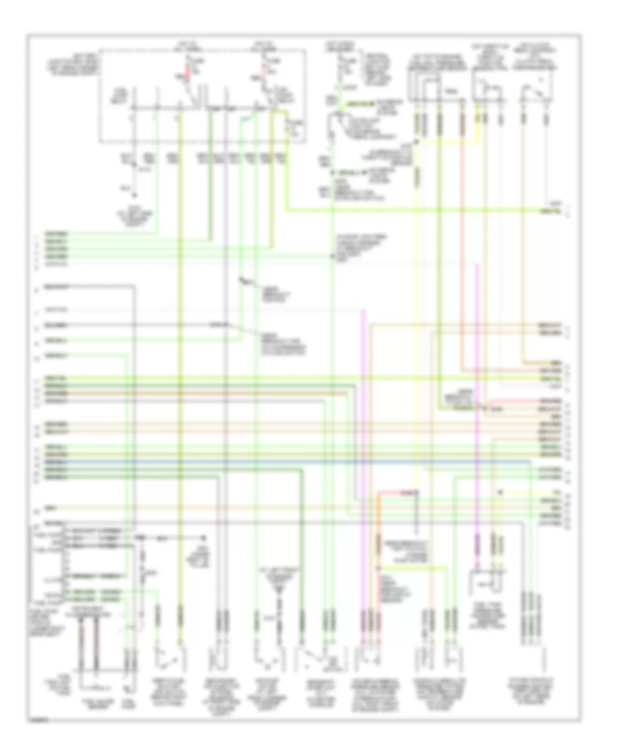
Engine Performance Wiring Diagram (1 of 4) for Ford Focus ZX5 SE 2005

List of elements for Engine Performance Wiring Diagram (1 of 4) for Ford Focus ZX5 SE 2005:
- (near breakout for dlc)
- 10-gl37
- 15-re16
- 15-re8
- 15-re8a
- 15s-re10a
- 15s-re13
- 15s-re8
- 15s-ta21
- 29-re14
- 30-re8
- 31-re8a
- 31s-bb16
- 31s-fa11
- 31s-gl6
- 31s-pa17
- 31s-pa21
- 31s-pa7
- 31s-re32
- 31s-rh1
- 31s-rl25
- 4-ec7
- 5-ec7
- 8-ce10
- 8-gl37
- 8-pa13
- 8-re22
- 8-rj13
- 8-rj17
- 8-rj22
- 9-re8
- 9-rj22
- 91-re8
- 91-re8a
- 91-re8b
- 91-rj16
- 91s-rl3
- A/c clutch relay
- A/c clutch rly
- A/c press sw
- Acc
- Air conditioning system
- Air pump rly
- Anti-theft system
- Battery
- Battery junction box (bjb) (left rear corner of engine compt)
- Battery junction box)
- C175b
- C270b
- C270e
- Can h
- Can l
- Central junction box (cjb) (behind left side of dash)
- Computer data lines system
- Cooling fans system
- Cruise control system
- Dual pressure switch (at right front of engine compt)
- Eng cool fan
- Engine cooling fan relay
- Evap canister purge valve (rear side of engine compt)
- Evap purge
- Evap vent
- Evaporative emission (evap) canister vent valve (under rear of vehicle)
- Feps
- Ftp sens
- Fuel pump
- Fuse 10a
- Fuse 20a
- Fuse 30a
- G103 (at left side of engine compt)
- G202 (at right "a" pillar)
- Ground
- Hi cool fan
- High speed fan control relay
- Hot at all times
- Ignition relay
- Ignition switch
- Imrc module
- Intake air temp
- Lo cool fan
- Lock
- Low speed cooling fan relay a
- Low speed cooling fan relay b
- Maf sens
- Maf sens sig
- Mass air flow (maf) sensor (on intake system)
- Off
- Overdrive sig
- Passive anti-theft transceiver module (on upper right side of steering column)
- Pats ind
- Pcm power diode
- Power hold relay
- Powertrain control module (pcm) (behind right side of dash, at base of "a" pillar)
- Psp sens
- Pwr hold rly
- Red
- Run
- Rx sig
- S118
- S154 (near breakout for two- way washer pump motor)
- S160
- S252
- S278
- Sig return
- Solid state
- Start
- Start relay
- Starter relay
- Starting/charging system
- Stoplamp
- Tx sig
- Vss out
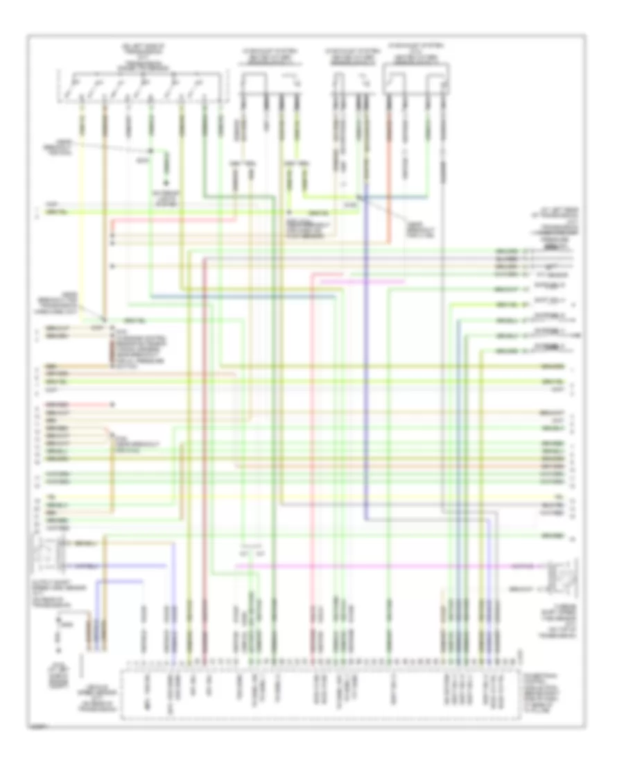
Engine Performance Wiring Diagram (2 of 4) for Ford Focus ZX5 SE 2005
List of elements for Engine Performance Wiring Diagram (2 of 4) for Ford Focus ZX5 SE 2005:
- (at left front of engine compt) g100
- (in door lock feed wiring harness, at breakout for g200) s267
- (near breakout for a/c compressor cycling switch)
- (near breakout for pcm)
- (near breakout for two-way washer pump motor)
- (near breakout to coil on plug 3)
- (not used)
- (on clutch pedal support) (m/t) clutch pedal position switch
- (on throttle body) throttle position sensor (tps)
- (on top of engine) fuel rail pressure/ temperature sensor
- 15-re16
- 15-rj16
- 15s-re31
- 15s-rg2
- 31-re31
- 31-rg2
- 31s-re32
- 8-rj16
- 91-rj16
- Air pump motor (at left front corner of engine compt)
- Air pump relay
- Battery junction box (bjb) (left rear corner of engine compt)
- C270f
- Central junction box (cjb) (behind left side of dash)
- Exterior lights system
- Fl mtr
- Fuel gauge sensor
- Fuel pump
- Fuel pump driver module (under right rear seat)
- Fuel pump relay
- Fuel tank pressure transducer sensor (in fuel tank)
- Fuel tank unit (on fuel tank)
- Fuse 10a
- Fuse 15a
- Fuse 30a
- G103 (at left side of engine compt)
- G301 (under right "b" pillar)
- Gearshift lever unit (a/t) (in center console)
- Gnd
- Hot at all times
- Hot in run or start
- Ifs sw
- Inertia fuel shutoff (ifs) switch (behind right kick panel)
- Instrument cluster system
- Intake manifold runner control (imrc) module (on left rear of engine)
- Manifold absolute pressure/ intake air temperature (map/iat) sensor (on intake system)
- Nca
- O/d off switch
- Power steering pressure sensor (2.3l: on power steering pump) (2.0l: right front of engine compt)
- Red
- S101 (near breakout for map/iat sensor)
- S118
- S121
- S159
- S194
- S197 (in breakout to throttle position sensor)
- S198
- S271
- S300
- S381
- Secondary air injection bypass solenoid (at right side of engine compt)
- Stoplamp switch (on brake pedal support)
- Stoplamp switch)
Engine Performance Wiring Diagram (3 of 4) for Ford Focus ZX5 SE 2005
List of elements for Engine Performance Wiring Diagram (3 of 4) for Ford Focus ZX5 SE 2005:
- (2.3l)
- (a/t)
- (at left rear of transmission) (a/t) transmission hardware unit
- (in exhaust system) (2.3l) heated oxygen sensor (ho2s) 13
- (in exhaust system) heated oxygen sensor (ho2s) 11
- (in exhaust system) heated oxygen sensor (ho2s) 12
- (m/t)
- (near breakout for c1168)
- (near breakout for pcm)
- (near breakout for transmission hardware unit)
- (on left side of transmission) (a/t) transmission range (tr) sensor
- (or 15s-ta37)
- 15s-ta17
- 15s-ta23
- 15s-ta24
- 15s-ta38a
- 15s-ta40
- 15s-ta41
- 15s-ta42
- 15s-ta63
- 15s-ta64
- 15s-ta65
- 2.0l
- 2.3l
- 8-bb6
- 8-rj15
- 8-rj29
- 8-rj41
- 8-ta27
- 8-ta36
- 9-rj29
- 9-ta27
- 91s-rj15
- 91s-rj41
- 91s-ta17
- A/t
- C175t
- Epc sol
- Exterior lights system
- G103 (at left side of engine compt)
- Ho2s 12 ctrl
- Ho2s 12 sig
- Ho2s 13 ctrl
- Ho2s 13 sig
- M/t
- Nca
- Oss sens
- Output shaft speed (oss) sensor (a/t) (on rear of transmission)
- Powertrain control module (pcm) (behind right side of dash, at base of "a" pillar)
- Pressure ctrl sol
- S161 (near breakout for mass air flow sensor)
- S163 (near breakout for c144)
- S187
- S190
- S191 (in engine control sensor extension wiring harness, near breakout for oil pressure switch)
- S252
- S275
- Shift sol a
- Shift sol b
- Shift sol c
- Shift sol d
- Shift sol e
- Sig return
- Tft sens
- Tft sensor
- Tr sens, 1
- Tr sens, 2
- Tr sens, d
- Tr sens, p/n
- Tr sens, rev
- Tss sens
- Turbine shaft speed (tss) sensor (a/t) (on top of transmission)
- Vehicle speed sensor (m/t) (on rear of transmission)
- Vss sig
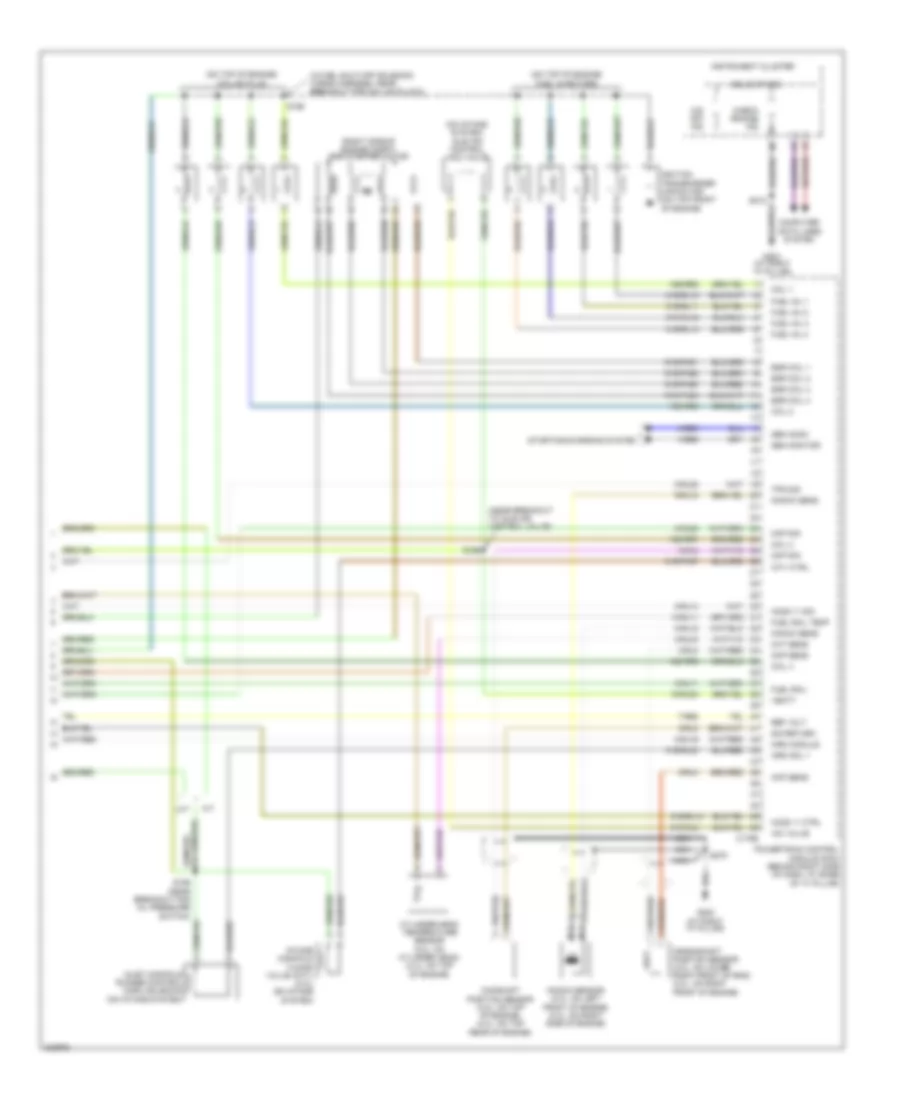
Engine Performance Wiring Diagram (4 of 4) for Ford Focus ZX5 SE 2005
List of elements for Engine Performance Wiring Diagram (4 of 4) for Ford Focus ZX5 SE 2005:
- (in fuel shut-off solenoid wiring harness, near breakout for coil on plug 2)
- (near breakout to idle air control valve)
- (on intake system) idle air control (iac) valve
- (on top of engine) coil on plug
- (on top of engine) fuel injectors
- (right side of engine compt) egr stepper motor
- 10-rj11
- 15-rl9a
- 15s-rr5
- 15s-rr6
- 15s-rr7
- 15s-rr8
- 31s-pa37
- 31s-rl10
- 31s-rl11
- 31s-rl12
- 31s-rl13
- 31s-rl20
- 31s-rl9
- 4-eb6
- 5-eb6
- 7-re8
- 8-rj11
- 8-rj14
- 8-rj16
- 8-rj18
- 8-rj20
- 8-rj28
- 8-rj3
- 8-rj33
- 8-rj4
- 9-rj18
- 9-rj3
- 9-rj4
- 91s-pa51
- 91s-pa52
- 91s-pa53
- 91s-pa54
- 91s-rj14
- A/t
- C175e
- Camshaft position sensor (2.0l: on top of engine) (2.3l: on top rear of engine)
- Check engine ind
- Cht sens
- Ckp sens
- Cmp sig
- Coil 1
- Coil 2
- Coil 3
- Coil 4
- Computer data lines system
- Crankshaft position sensor (2.0l: on lower right front of eng) (2.3l: on right front of engine)
- Cylinder-head temperature sensor (2.0l: on cylinder head) (2.3l: on top of engine)
- Egr coil 1
- Egr coil 2
- Egr coil 3
- Egr coil 4
- Fuel inj 1
- Fuel inj 2
- Fuel inj 3
- Fuel inj 4
- Fuel rail
- Fuel rail temp
- G202 (at right "a" pillar)
- G203 (at right "a" pillar)
- Gen comm
- Gen monitor
- Ho2s 11 ctrl
- Ho2s 11 sig
- Iac valve
- Ignition transformer capacitor (on top front of engine)
- Imrc module
- Imrc sol 1
- Imtv ctrl
- Inlet manifold runner control (imrc) solenoid (on intake system)
- Instrument cluster
- Intake manifold tuning valve (imtv) (2.3l) (on intake system)
- Knock sens
- Knock sensor (2.0l: on left front of engine) (2.3l: on right side of engine)
- M/t
- Map sig
- Nca
- O/d off ind
- Powertrain control module (pcm) (behind right side of dash, at base of "a" pillar)
- Ref volt
- S156 (near breakout for oil pressure switch)
- S169
- S199
- S212
- S278
- Sig return
- Solid state
- Starting/charging system
- Tps sig
- Vbatt