ENGINE PERFORMANCE
2.3L
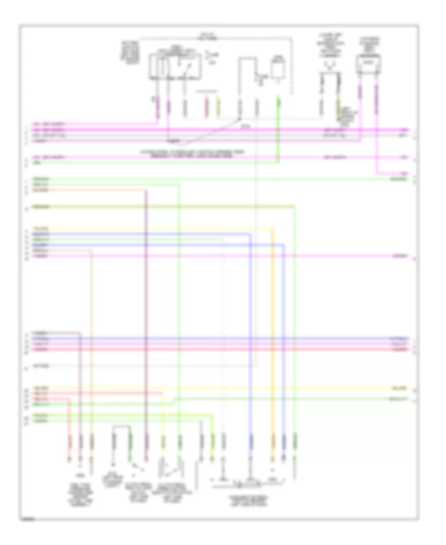
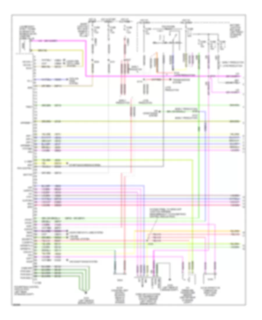
2.3L, Engine Performance Wiring Diagram (1 of 5) for Ford Fusion S 2007

List of elements for 2.3L, Engine Performance Wiring Diagram (1 of 5) for Ford Fusion S 2007:
- (in dash panel to headlamp junction harness, near breakout to powertrain control
- A/c evaporative thermistor (right side of dash)
- A/c pressure transducer sensor (right front of engine)
- Accr
- Acet
- Acpt
- Air conditioning system
- App 1
- App 2
- App 3
- Appsref 1
- Appsref 2
- Appsrtn 1
- Appsrtn 2
- Battery junction box (bjb) (left side of engine compt)
- Boo
- Bps
- C sigrtn
- C vref
- C175b
- C2280a
- Canvnt
- Case gnd
- Cbp18
- Cbp42
- Cbp46
- Ccb08
- Cdb08
- Cdc12
- Ce114
- Ce132
- Ce302
- Ce404
- Ce608
- Ce903
- Ce904
- Ces09
- Cet40
- Ch302
- Computer data lines system
- Cooling fans system
- Cpp bt
- Cpp tt
- Cruise control system
- Eair
- Eairm
- Early production
- Evap canister vent control solenoid (rear of vehicle chassis)
- Evaporative emission (evap) canister purge valve (lower right strut tower)
- Evmv
- Fc v
- Feps
- Fpc
- Fpm
- Ftpt
- Ftptref
- Fuse 15a
- Fuse 40a
- Fuse 7.5a
- G102 (left rear of engine compt)
- Gd120
- Hot at all times
- Hot in start or run
- Hs can +
- Hs can -
- Iat
- Ignition
- Injpwrm
- Kapwr
- Late production
- Le136
- Le137
- Le230
- Le424
- Maf
- Mafrtn
- Mass air flow/intake air temperature (maf/iat) sensor (left front of engine compt)
- Module (pcm))
- Output shaft speed (oss) sensor (top of transmission)
- Pcm control
- Pcm power relay
- Powertrain control module (pcm) (left rear of engine compt)
- Pwr gnd
- Pwr gnd 1
- Pwr gnd 2
- Pwr gnd 3
- Re136
- Re137
- Re325
- Re407
- Res08
- S121
- S124
- S127
- S129
- S143 (late production)
- S144
- Sbb45
- Sbp07
- Sccs
- Sccsrtn
- Smart junction box (sjb) (base of left "a" pillar)
- Smc
- Starting/charging system
- Trsw
- Vdb04
- Vdb05
- Ve225
- Ve701
- Ve702
- Ve703
- Ve740
- Ve806
- Ve808
- Ve922
- Vec03
- Ves10
- Vh406
- Vh433
- Vpwr
- Vpwr1
- Vssin
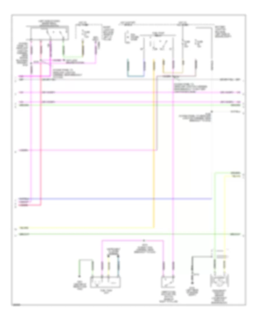
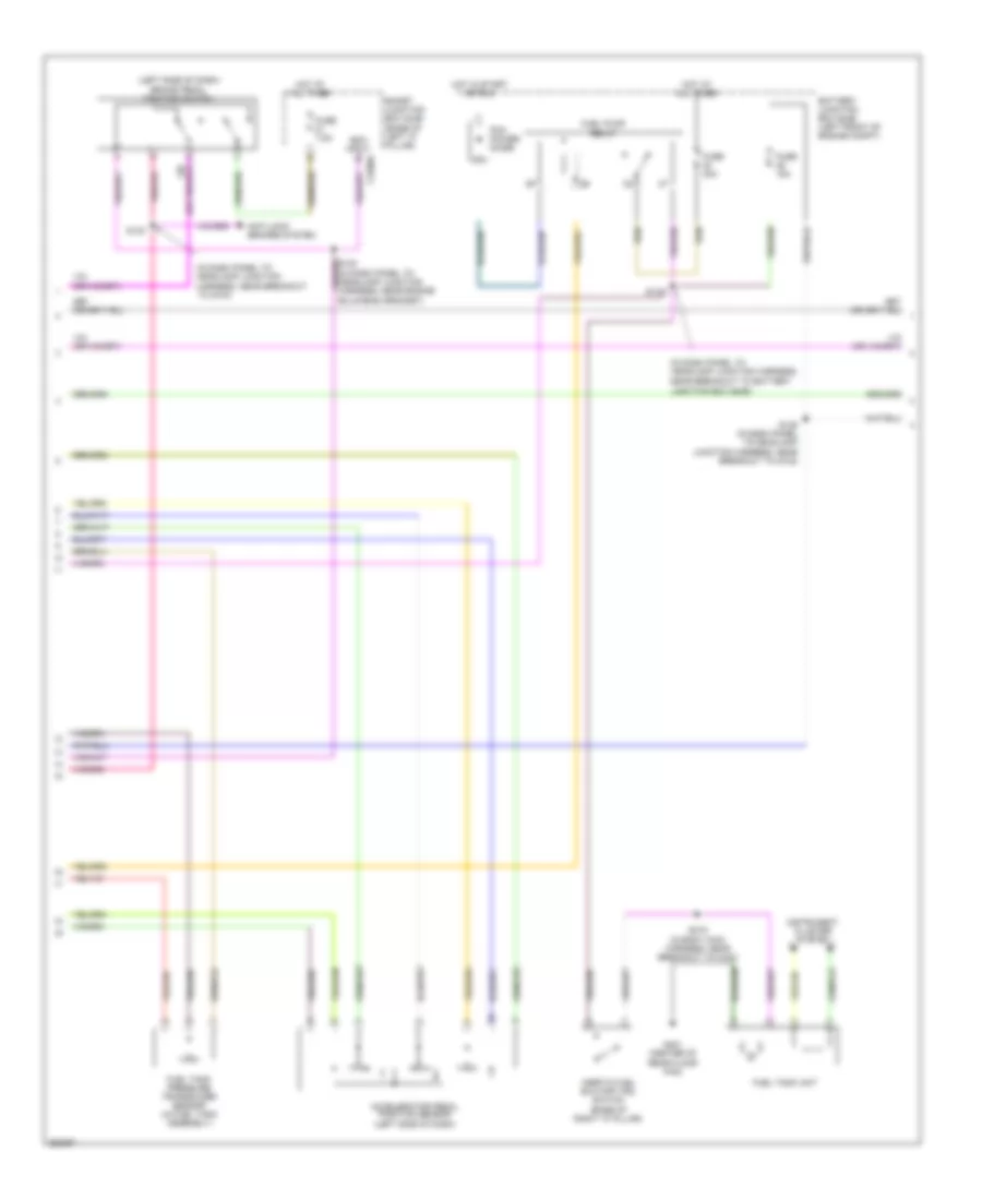
2.3L, Engine Performance Wiring Diagram (2 of 5) for Ford Fusion S 2007
List of elements for 2.3L, Engine Performance Wiring Diagram (2 of 5) for Ford Fusion S 2007:
- (in dash panel to headlamp junction harness, near breakout to battery junction box (bjb))
- (left front of engine compt) g103
- (lower left side of engine block) (pzev) peta pump motor
- (pzev) high current peta pump relay
- (top rear of engine) (pzev) peta solenoid
- Accelerator pedal position sensor (left side of dash)
- Battery junction box (bjb) (left side of engine compt)
- Clutch pedal position (cpp) switch (left side of dash)
- Clutch pedal speed control deactivator switch (left side of dash)
- Fnr5 relay
- Fuel tank pressure transducer sensor (in fuel tank assembly)
- Fuse 40a
- Fuse 5a
- G102 (left rear of engine compt)
- Hot at all times
- Nca
- S139
- S140
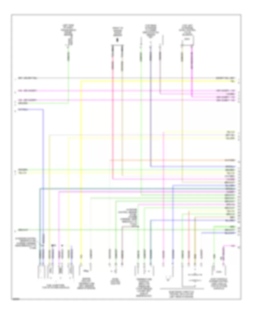
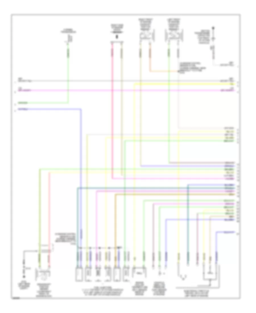
2.3L, Engine Performance Wiring Diagram (3 of 5) for Ford Fusion S 2007
List of elements for 2.3L, Engine Performance Wiring Diagram (3 of 5) for Ford Fusion S 2007:
- (in dash panel to headlamp junction harness, near breakout to battery
- (in dash panel to headlamp junction harness, near breakout to c1443)
- (in dash panel to headlamp junction harness, near engine bulkhead grommet) s120
- (left side of dash) brake pedal position switch
- Anti-lock brakes system
- Battery junction box (bjb) (left side of engine compt)
- Boo input c2280a
- Crankshaft position sensor (lower right front of engine block)
- Fuel pump relay
- Fuel tank unit
- Fuse 15a
- Fuse 30a
- Fuse 7.5a
- G102 (left rear of engine compt)
- G401 (center of rear floor pan)
- Hot at all times
- Hot in start or run
- Inertia fuel shutoff (ifs) switch (base of right "a" pillar)
- Instrument cluster system
- Junction box (bjb))
- Nca
- Pcm power diode
- S115
- S125 (in dash panel to headlamp junction harness, near breakout to g102)
- S130
- S133
- S415 (in body main harness, near breakout to c433)
- Smart junction box (sjb) (base of left "a" pillar)
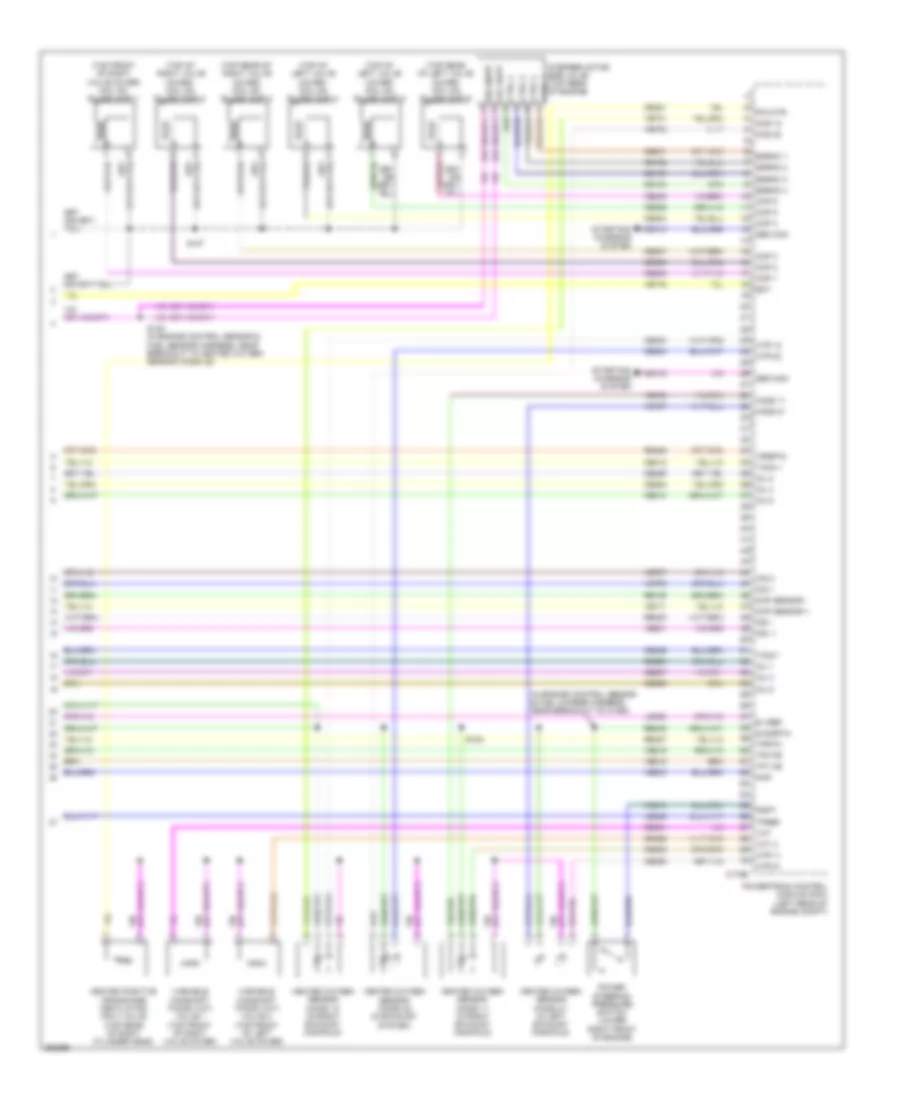
2.3L, Engine Performance Wiring Diagram (4 of 5) for Ford Fusion S 2007
List of elements for 2.3L, Engine Performance Wiring Diagram (4 of 5) for Ford Fusion S 2007:
- (front of engine) knock sensor
- (in engine control sensor & fuel charge harness, near breakout to c1368)
- (in engine control sensor & fuel charge harness, near breakout to c1543) s113
- (left side of dash) transmission range sensor
- (top left of engine) swirl control valve solenoid
- (top rear of engine) cylinder identification sensor
- Electronic throttle control (etc) motor (left rear of engine)
- Engine coolant temperature (ect) sensor (rear of engine)
- Fuel injectors (top of intake manifold)
- Inlet manifold runner control (imrc) module (top of intake manifold)
- Nca
- Park/ neutral
- S108
- Swirl control monitor
- Temperature manifold absolute pressure (tmap) sensor (lower left side of engine block)
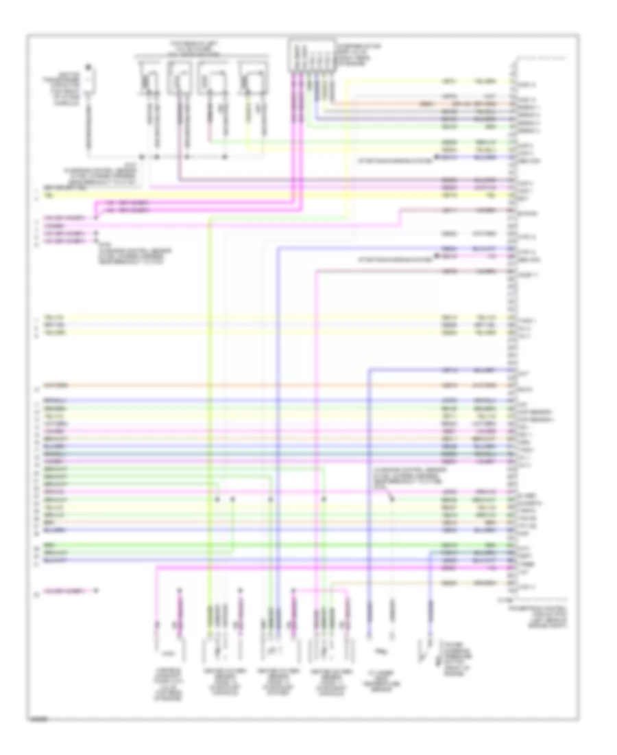
2.3L, Engine Performance Wiring Diagram (5 of 5) for Ford Fusion S 2007
List of elements for 2.3L, Engine Performance Wiring Diagram (5 of 5) for Ford Fusion S 2007:
- (in engine control sensor & fuel charge harness, near breakout to c175e) s102
- (top rear of left valve cover) coil on plugs (cop)
- Bvpwr
- C175e
- Cdc10
- Cdc15
- Ce102
- Ce103
- Ce104
- Ce205
- Ce206
- Ce207
- Ce208
- Ce233
- Ce234
- Ce235
- Ce301
- Ce303
- Ce304
- Ce305
- Ce306
- Ce316
- Ce411
- Ce412
- Ce421
- Ce426
- Cht
- Cid
- Ckp sensor +
- Ckp sensor -
- Cms 12
- Cms 13
- Cop 1
- Cop 2
- Cop 3
- Cop 4
- Ctrl 1
- Ctrl 2
- Ctrl 3
- Ctrl 4
- Cylinder- head temperature sensor
- E sigrtn
- E vref
- Ect
- Egrmc 1
- Egrmc 2
- Egrmc 3
- Egrmc 4
- Gen com
- Gen mon
- Heated oxygen sensor (ho2s) 11 (in exhaust manifold)
- Heated oxygen sensor (ho2s) 12 (in exhaust manifold)
- Heated oxygen sensor (ho2s) 13 (in exhaust system)
- Ho2s 11
- Htr 11
- Htr 12
- Htr 13
- Ignition transformer capacitor (top front of intake
- Imrc
- Imtv
- Inj 1
- Inj 2
- Inj 3
- Inj 4
- Ks1 +
- Ks1 -
- Le111
- Le423
- Le428
- Manifold)
- Map
- Power steering pressure switch (front of engine)
- Powertrain control module (pcm) (left rear of engine compt)
- Pspt
- Re135
- Re323
- Re405
- Re427
- S107 (in engine control sensor & fuel charge harness, near breakout to c1161)
- S109 (in engine control sensor & fuel charge harness, near breakout to c191)
- Scvm
- Starting/charging system
- Stepper motor egr valve (right rear of engine)
- Tacm +
- Tacm -
- Tp1 ns
- Tp2 ps
- Tpref
- Tprtn
- Variable camshaft timing (vct) valve (top rear of engine)
- Vcs10
- Vct
- Ve519
- Ve706
- Ve711
- Ve712
- Ve716
- Ve731
- Ve733
- Ve735
- Ve801
- Ve803
- Ve818
- Ve819
- Vol supp
- Vol supp vol supp
3.0L
3.0L, Engine Performance Wiring Diagram (1 of 4) for Ford Fusion S 2007
List of elements for 3.0L, Engine Performance Wiring Diagram (1 of 4) for Ford Fusion S 2007:
- (early production) s129
- (in dash panel to headlamp junction harness, near breakout to powertrain control module (pcm))
- (lower right strut tower) evaporative emission (evap) canister purge valve
- (or cbp47)
- A/c evaporative thermistor (right side of dash)
- A/c pressure transducer sensor (center rear of engine compt)
- Accr
- Acet
- Acpt
- Air conditioning system
- App 1
- App 2
- App 3
- Appsref 1
- Appsref 2
- Appsrtn 1
- Appsrtn 2
- Battery junction box (bjb) (left front of engine compt)
- Boo
- Bps
- C sigrtn
- C vref
- C175b
- C2280a
- C2280b
- Canvnt
- Case gnd
- Cbp13
- Cbp18
- Cbp42
- Cbp46
- Cbp47
- Ccb08
- Cdb08
- Cdc12
- Ce114
- Ce132
- Ce302
- Ce608
- Ces09
- Cet40
- Ch302
- Computer data lines system
- Cooling fans system
- Cruise control system
- Early production
- Evap canister vent control solenoid (rear of vehicle chassis)
- Evmv
- Fc v
- Feps
- Fpc
- Fpm
- Ftpt
- Ftptref
- Fuse 10a
- Fuse 15a
- Fuse 40a
- Fuse 7.5a
- G102 (left rear of engine compt)
- Gd120
- Hot at all times
- Hot in start
- Hot in start or run
- Hs can +
- Hs can -
- Iat
- Ignition
- Injpwrm
- Kapwr
- Late production
- Le136
- Le137
- Le230
- Le424
- Maf
- Mafrtn
- Mass air flow/intake air temperature (maf/iat) sensor (left front of engine compt)
- Pcm control
- Pcm power relay
- Powertrain control module (pcm) (left rear of engine compt)
- Pwr gnd
- Pwr gnd 1
- Pwr gnd 2
- Pwr gnd 3
- Re136
- Re137
- Re325
- Re407
- Res08
- S119
- S121
- S124
- S127
- S142 (early production)
- S143 (late production)
- S144
- S232
- Sbp07
- Sccs
- Sccsrtn
- Smart junction box (sjb) (base of left "a" pillar)
- Smc
- Smr
- Starting/charging system
- Transmissions system
- Trsw
- Vdb04
- Vdb05
- Ve225
- Ve701
- Ve702
- Ve703
- Ve740
- Ve808
- Ve922
- Vec03
- Ves10
- Vh406
- Vh433
- Vpwr
- Vpwr1
3.0L, Engine Performance Wiring Diagram (2 of 4) for Ford Fusion S 2007
List of elements for 3.0L, Engine Performance Wiring Diagram (2 of 4) for Ford Fusion S 2007:
- (in dash panel to headlamp junction harness, near breakout to battery
- (in dash panel to headlamp junction harness, near breakout to g103)
- (left side of dash) brake pedal position switch
- Accelerator pedal position sensor (left side of dash)
- Anti-lock brakes system
- Battery junction box (bjb) (left front of engine compt)
- Boo input c2280a
- Fuel pump relay
- Fuel tank pressure transducer sensor (in fuel tank assembly)
- Fuel tank unit
- Fuse 15a
- Fuse 30a
- Fuse 7.5a
- G401 (center of rear floor pan)
- Hot at all times
- Hot in start or run
- Inertia fuel shutoff (ifs) switch (base of right "a" pillar)
- Instrument cluster system
- Junction box (bjb))
- Pcm power diode
- S125 (in dash panel to headlamp junction harness, near breakout to g102)
- S130
- S133
- S415 (in body main harness, near breakout to c433)
- Smart junction box (sjb) (base of left "a" pillar)
3.0L, Engine Performance Wiring Diagram (3 of 4) for Ford Fusion S 2007
List of elements for 3.0L, Engine Performance Wiring Diagram (3 of 4) for Ford Fusion S 2007:
- (in engine control sensor & fuel charge harness, near breakout to c175e) s103
- (in engine control sensor & fuel charge harness, near breakout to c181)
- (left front of engine) camshaft position sensor 2
- (right front of engine) camshaft position sensor 1
- (right side of engine) knock sensor
- 6 speed transmission
- Crankshaft position sensor (lower right front of engine block)
- Electronic throttle control (etc) motor (left rear of engine)
- Engine coolant temperature (ect) sensor (rear of engine)
- Fuel injectors (1, 2, 3: top right of intake manifold) (5, 6: left side of intake manifold) (4: top left of intake manifold)
- G102 (left rear of engine compt)
- Ignition transformer capacitor (top front of intake
- Lock start
- Manifold absolute pressure (map) sensor (top rear of engine)
- Manifold)
- Nca
- S108
- S115
3.0L, Engine Performance Wiring Diagram (4 of 4) for Ford Fusion S 2007
List of elements for 3.0L, Engine Performance Wiring Diagram (4 of 4) for Ford Fusion S 2007:
- (in engine control sensor & fuel charge harness, near breakout to c1450)
- (top front of right valve cover) coil on plugs (cop) 1
- (top of right valve cover) coil on plugs (cop) 2
- (top of left valve cover) coil on plugs (cop) 4
- (top of left valve cover) coil on plugs (cop) 5
- (top rear of right valve cover) coil on plugs (cop) 3
- (top rear of left valve cover) coil on plugs (cop) 6
- C175e
- Cdc10
- Cdc15
- Ce102
- Ce103
- Ce104
- Ce205
- Ce206
- Ce207
- Ce208
- Ce209
- Ce210
- Ce233
- Ce234
- Ce235
- Ce236
- Ce301
- Ce303
- Ce304
- Ce305
- Ce306
- Ce307
- Ce308
- Ce321
- Ce412
- Ce421
- Ce422
- Ce426
- Cid 1
- Cid 2
- Ckp sensor +
- Ckp sensor -
- Cms 12
- Cms 22
- Cop 1
- Cop 2
- Cop 3
- Cop 4
- Cop 5
- Cop 6
- Ctrl 1
- Ctrl 2
- Ctrl 3
- Ctrl 4
- E sigrtn
- E vref
- Ect
- Egrmc 1
- Egrmc 2
- Egrmc 3
- Egrmc 4
- Gen com
- Gen mon
- Heated oxygen sensor (ho2s) 11 (in right exhaust manifold)
- Heated oxygen sensor (ho2s) 12 (in right exhaust manifold)
- Heated oxygen sensor (ho2s) 21 (in left exhaust manifold)
- Heated oxygen sensor (ho2s) 22 (in exhaust system)
- Heated positive crankcase ventilation (pcv) valve (top rear of right cylinder head)
- Ho2s 11
- Ho2s 21
- Htr 11
- Htr 12
- Htr 21
- Htr 22
- Inj 1
- Inj 2
- Inj 3
- Inj 4
- Inj 5
- Inj 6
- Ks1 +
- Ks1 -
- Le423
- Le428
- Map
- Pcvhtr
- Power steering pressure switch (lower right front of engine)
- Powertrain control module (pcm) (left rear of engine compt)
- Pspt
- Re135
- Re323
- Re405
- Re427
- Re429
- S102
- S107
- S149 (in engine control sensor & fuel sensor harness, near breakout to heated oxygen sensor (ho2s) 22)
- Starting/ charging system
- Stepper motor egr valve (top rear of engine)
- Tacm +
- Tacm -
- Tp1 ns
- Tp2 ps
- Tpref
- Tprtn
- Variable camshaft timing (vct) valve 1 (top front of right valve cover)
- Variable camshaft timing (vct) valve 2 (top front of left valve cover)
- Vcs10
- Vct
- Vct 2
- Ve706
- Ve707
- Ve711
- Ve716
- Ve731
- Ve733
- Ve735
- Ve737
- Ve801
- Ve803
- Ve818
- Ve819
- Vol supp
- Vol supp vol supp
- Vrsrtn