ENGINE PERFORMANCE
1.5L TURBO
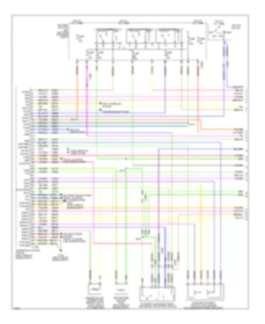
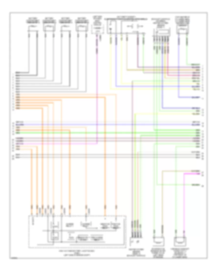
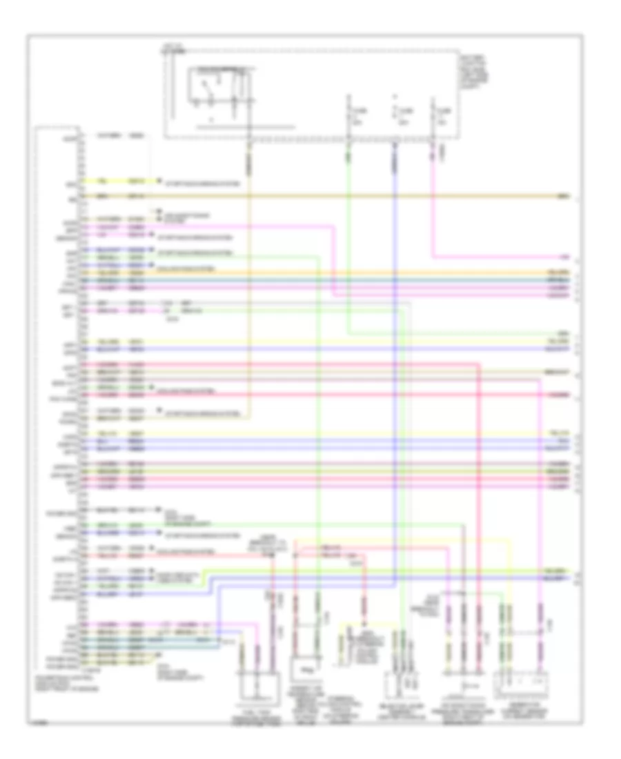
1.5L Turbo, Engine Performance Wiring Diagram (1 of 6) for Ford Fusion Titanium 2014

List of elements for 1.5L Turbo, Engine Performance Wiring Diagram (1 of 6) for Ford Fusion Titanium 2014:
- (not used)
- 10a
- Accr
- Air conditioning system
- Apprtn1
- Apprtn2
- Appvref1
- Appvref2
- Battery junction box (bjb) (left side of engine compt)
- C1010
- C1026
- C1035a
- C1915b
- C215
- C219
- C248
- C315
- Cact
- Canv
- Cbb26
- Cdc12
- Cdc15
- Cdc35
- Ce113
- Ce114
- Ce170
- Ce233
- Ce436
- Ce515
- Ce608
- Cec01
- Cec02
- Ch302
- Ch307
- Computer data lines system
- Cooling fans system
- Cpc
- Evapcp
- Fpc
- Fpm
- Fppwr
- Fprtn
- Fuel lvl2
- Fuel pump assembly (top of fuel tank)
- Fuel pump control module (left front of luggage compt)
- Fuel pump relay
- Fuel rtn
- Fuel sndr
- Fuel sndr sig
- Fuse
- Fuse 10a
- Fuse 15a
- Fuse 20a
- Fuse 30a
- G304 (left "c" pillar)
- Gd304
- Genmon
- Gnd
- Hfc
- Hot at all times
- Hot w/ run/ start relay energized
- Hs3 can +
- Hs3 can -
- Htr12
- Instrument panel cluster (ipc) module
- Isp-r
- Le136
- Le137
- Le230
- Le423
- Lfc
- Lin
- Nca
- Pcm power relay
- Pcm wake
- Power distribution system
- Powertrain control module (right front of engine)
- Re136
- Re137
- Re230
- Re242
- Re320
- Re406
- Re407
- Re515
- Return
- Rmc32
- Rmc33
- S415
- S419
- Sigrtn
- Smc
- Sme
- Smr
- Starting/ charging system
- Starting/charging system
- Vacc
- Vdb29
- Vdb30
- Vdn06
- Ve225
- Ve462
- Ve518
- Ve804
- Vmc11
- Vmc23
- Vpwr
- Vref
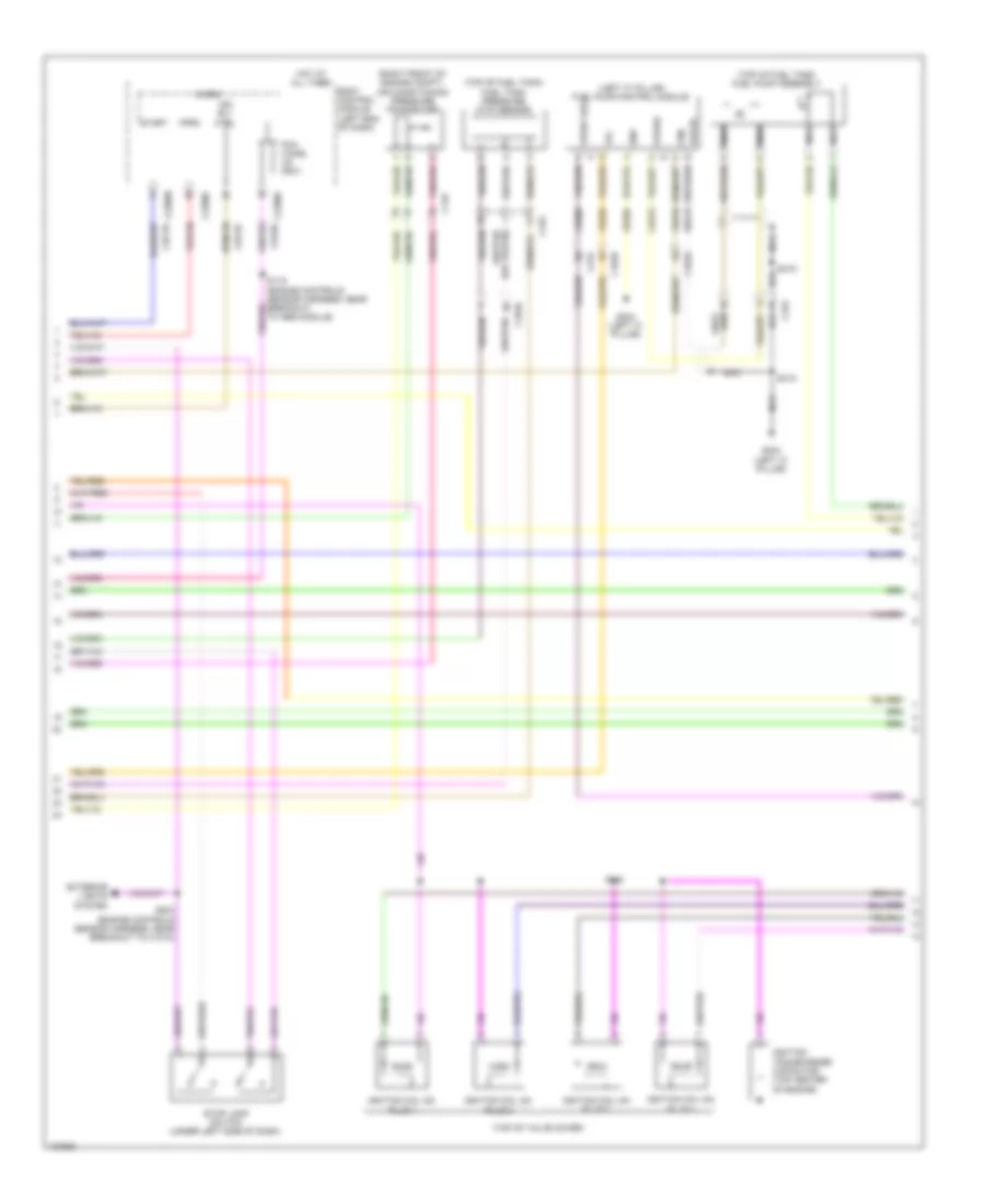
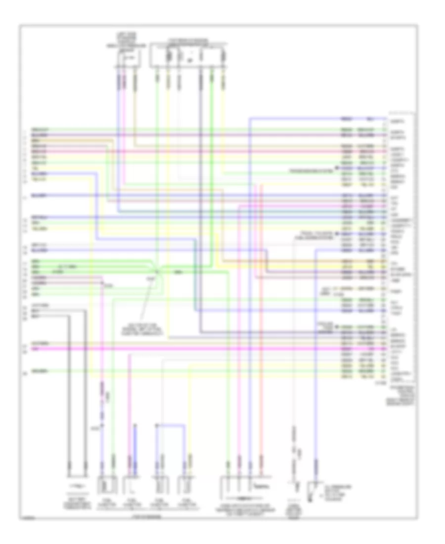
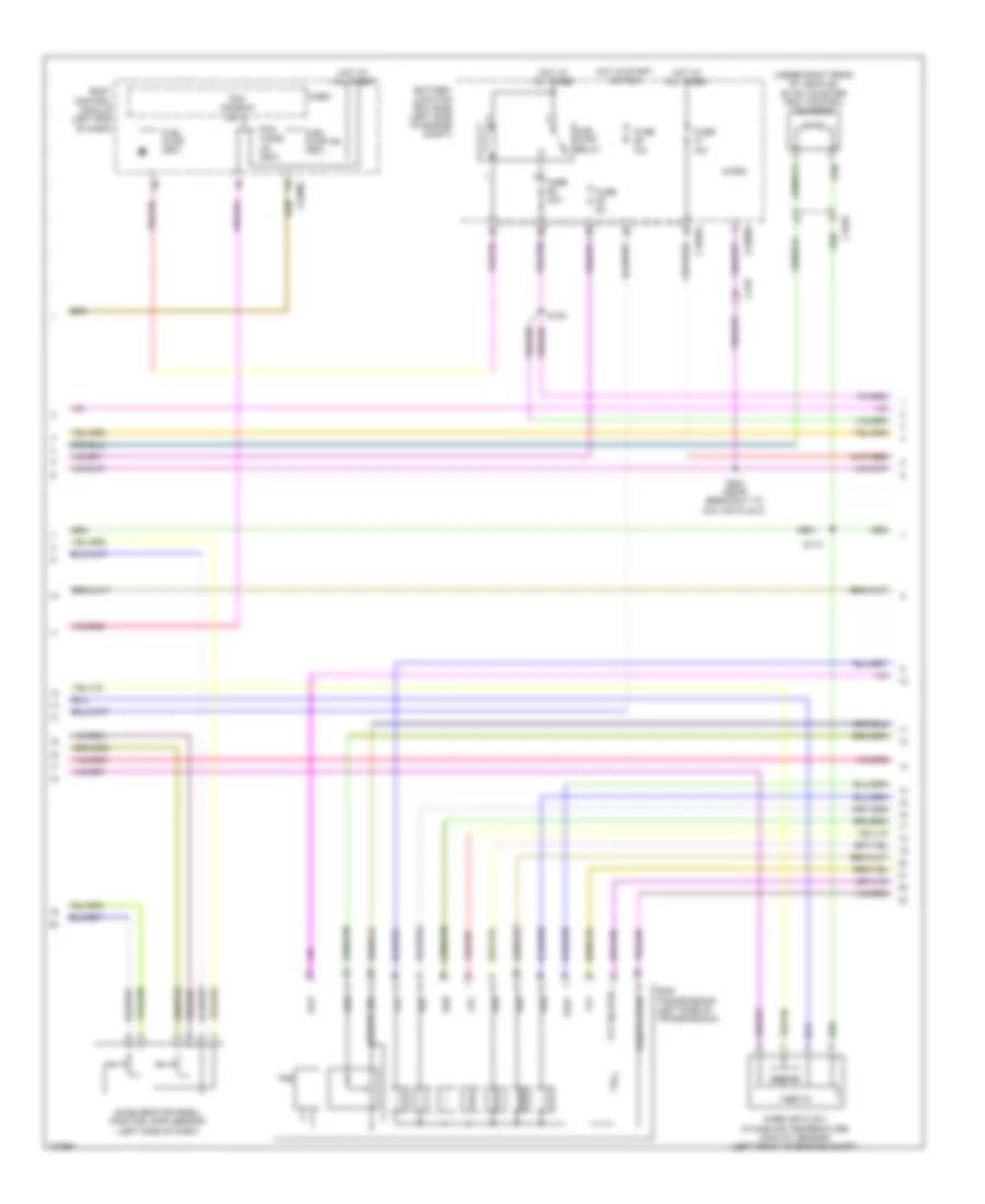
1.5L Turbo, Engine Performance Wiring Diagram (2 of 6) for Ford Fusion Titanium 2014
List of elements for 1.5L Turbo, Engine Performance Wiring Diagram (2 of 6) for Ford Fusion Titanium 2014:
- (engine controls sensor harness, near breakout to pcm)
- (engine controls sensor harness, near breakout to pcm) s134
- (instrument panel wiring harness, near breakout to g202)
- (not used)
- (right front of engine compt) air conditioning pressure transducer
- (right front of engine compt) charge air cooler coolant temperature sensor
- (right rear of engine) turbocharger boost pressure sensor
- (top of engine) fuel pressure sensor
- (top of fuel tank) (saddle tank) fuel level sensor
- (top of fuel tank) fuel tank pressure (ftp) sensor
- Accelerator pedal position sensor (top of accelerator pedal assembly)
- C1010
- C1026
- C145
- C219
- C315
- G101 (left front of engine compt)
- Intake air temperature sensor (left front of engine compt)
- Nca
- Pnk
- S105 (front park aid sensor harness, near breakout to active grille shutter)
- S131 (engine controls sensor harness, near breakout to pcm)
- S133
- S204 (engine controls sensor harness, near breakout to coil on plug 3)
- S205 (main wiring harness, in breakout to steering column control module)
- S214
- S216 (instrument panel wiring harness, near breakout to g202)
- Selector lever assembly (center console)
- Sst rtn
- Sst+
- Sst-
- Stop lamp switch (top of brake pedal assembly)
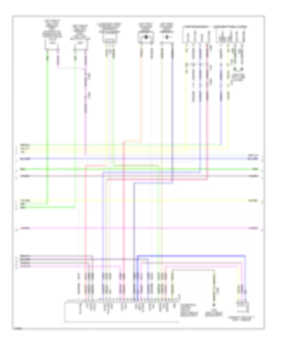
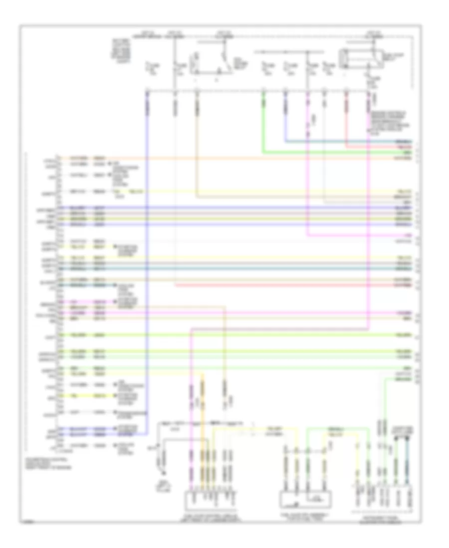
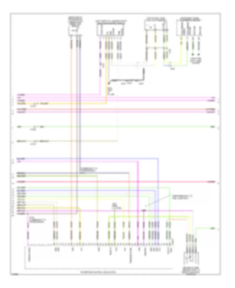
1.5L Turbo, Engine Performance Wiring Diagram (3 of 6) for Ford Fusion Titanium 2014
List of elements for 1.5L Turbo, Engine Performance Wiring Diagram (3 of 6) for Ford Fusion Titanium 2014:
- (behind right end of front grille) ambient air temperature sensor
- (engine controls sensor harness, near breakout to coil on plug 3) s126
- (on generator) generator current sensor
- Aat
- Acpt
- App1
- App2
- Bcs2 alt
- Body control module (left end of dash)
- Bpp
- Bps
- C1026
- C134
- C146
- C1915b
- C219
- C2280b
- C2280c
- C2280h
- Cbb07
- Ccb08
- Cdc10
- Cdc54
- Ce226
- Ce237
- Ce420
- Ce436
- Ces09
- Cet42
- Cet43
- Computer data lines system
- Flp
- Ftp
- Fuel pump (fet)
- G104 (right side of engine compt)
- Gd113
- Gencom
- Ho2s12
- Hs1 can+
- Hs1 can-
- Iat
- Micro
- Pcm rc
- Powertrain control module (right front of engine)
- Pwr gnd
- S112
- Smcs
- Sst+
- Sst-
- Starting/ charging system
- Tcbp
- Vbv
- Vdb04
- Vdb05
- Vdc61
- Ve701
- Ve702
- Ve727
- Ve731
- Ve740
- Ve750
- Ve803
- Ve922
- Vh433
- Vpwr
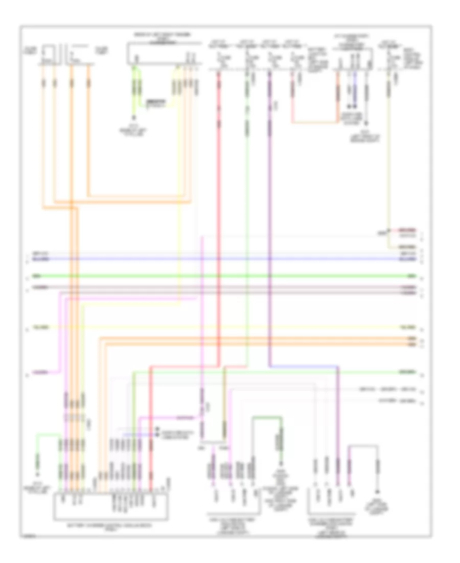
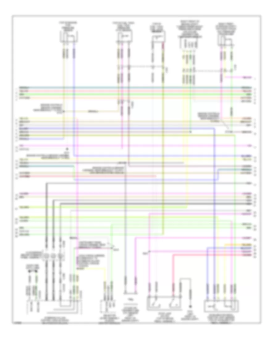
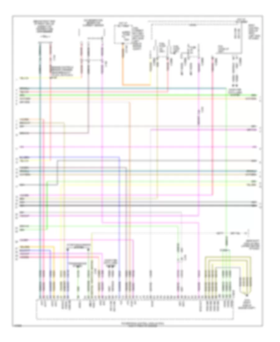
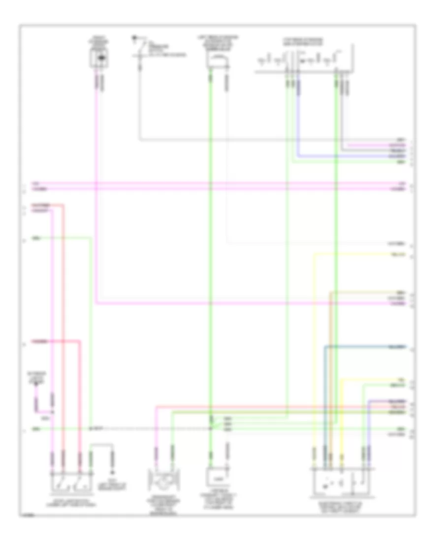
1.5L Turbo, Engine Performance Wiring Diagram (4 of 6) for Ford Fusion Titanium 2014
List of elements for 1.5L Turbo, Engine Performance Wiring Diagram (4 of 6) for Ford Fusion Titanium 2014:
- (in exhaust, downstream of catalytic converter) heated oxygen sensor 12
- (rear of exhaust manifold) universal heated oxygen sensor 11
- (right front side of cylinder head) variable camshaft timing solenoid 12
- (right rear of engine) evaporative emission purge valve
- (top left front of cylinder head) variable camshaft timing solenoid 11
- (top right side of engine) fuel injection pump
- (under right rear of vehicle) evap canister vent valve
- Atfpc
- Atfpm
- C1010
- C1026
- C1915e
- Ce205
- Ce206
- Ce207
- Ce208
- Ce226
- Ce304
- Ce305
- Ce412
- Ce426
- Cet05
- Cet07
- Cet09
- Cet49
- Cmp12
- Cop2d
- Cop3b
- Electronic throttle control (etc) (on throttle body)
- Evap vapor blocking valve
- Fvr
- Fvrrtn
- Inj1
- Inj1rtn
- Inj2
- Inj2rtn
- Inj3
- Inj3rtn
- Inj4
- Inj4rtn
- Ks1+
- Ks1-
- Le451
- Lpc
- Nca
- Power distribution system
- Powertrain control module (right front of engine)
- Re205
- Re206
- Re207
- Re208
- Re226
- Re323
- Re405
- S113
- S147
- Sigrtn
- Ssa
- Ssc
- Tacm+
- Tacm-
- Tft
- Tp1
- Tp2
- Tspc
- Uo2s11
- Uo2spc11
- Ve707
- Ve801
- Ve818
- Ve819
- Ve826
- Vet27
- Vyt11
- Vyt12
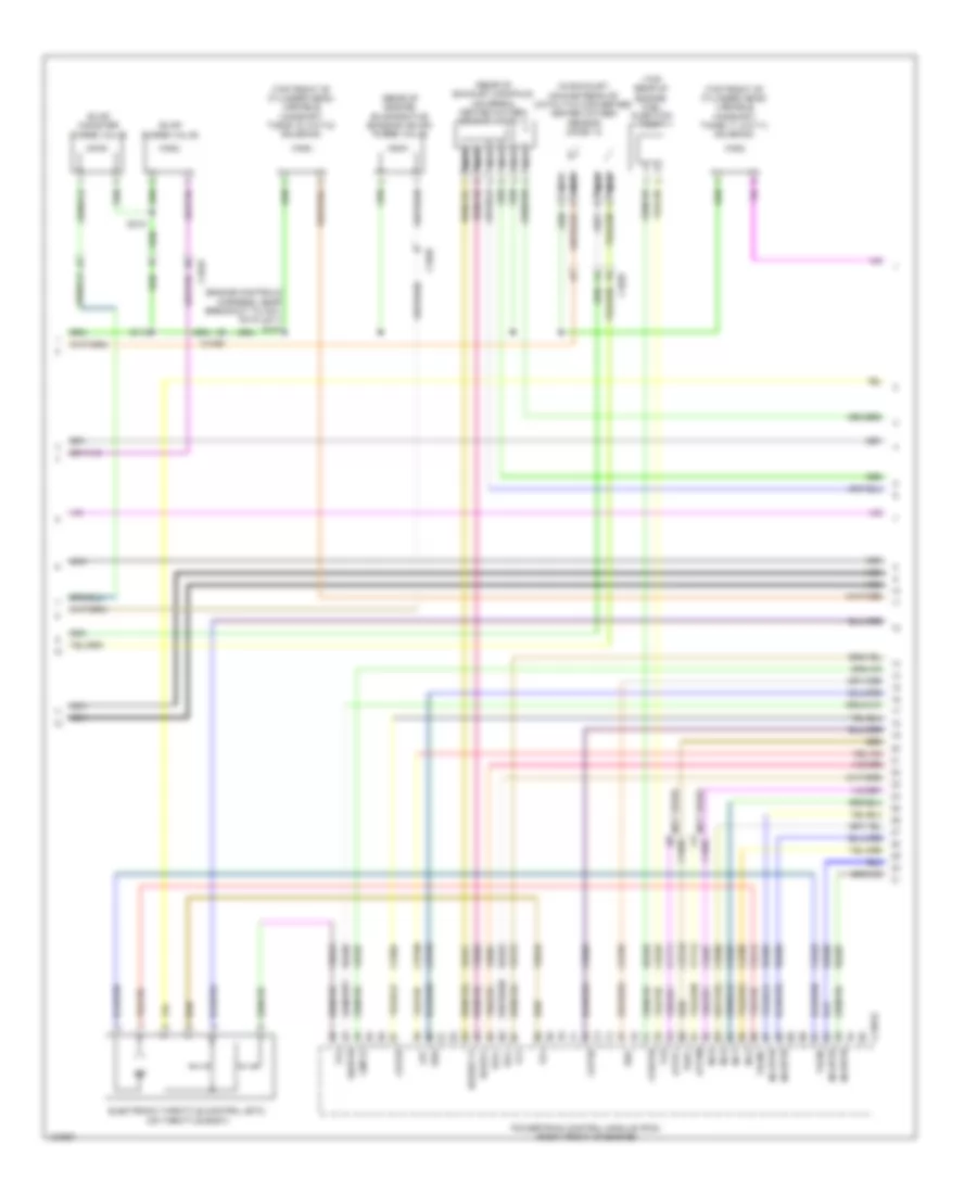
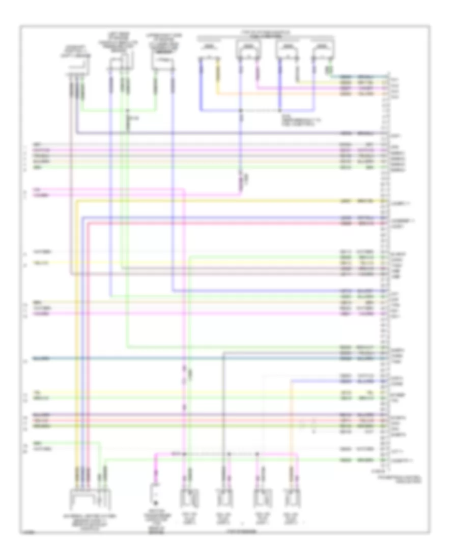
1.5L Turbo, Engine Performance Wiring Diagram (5 of 6) for Ford Fusion Titanium 2014
List of elements for 1.5L Turbo, Engine Performance Wiring Diagram (5 of 6) for Ford Fusion Titanium 2014:
- (bottom right side of engine) turbocharger bypass valve
- (left front of engine) charge air cooler pump
- (lower left front of engine) engine coolant pump clutch
- (right front of engine compt) active grill shutter
- (right rear of engine) turbocharger wastegate regulating valve solenoid
- (top left rear of engine) intake air temperature sensor 2
- (top of engine, above cylinder)
- (top right side of engine)
- C1026
- C134
- C139
- Coil on plug (cop) 1
- Coil on plug (cop) 2
- Coil on plug (cop) 3
- Coil on plug (cop) 4
- Fuel injector
- G110 (right front of engine)
- Gnd
- Knock sensor 1 (left rear of engine)
- Power distribution system
- Pump ctrl
- Pwr
- S110
- S144
- S148
- S151
1.5L Turbo, Engine Performance Wiring Diagram (6 of 6) for Ford Fusion Titanium 2014
List of elements for 1.5L Turbo, Engine Performance Wiring Diagram (6 of 6) for Ford Fusion Titanium 2014:
- (engine controls harness, near breakout to c1386)
- (engine controls harness, near breakout to coil on plug 1) s149
- (engine controls harness, near breakout to fuel rail pressure) s146
- (lower right front of engine block) crankshaft position sensor
- (near breakout to fuel rail pressure) s145
- (right rear of cylinder head) engine coolant temperature sensor
- (top front
- (top left front of engine) manifold absolute pressure & temperature sensor
- (top left rear of cylinder head) camshaft position sensor 11
- (top right rear of cylinder head) camshaft position sensor 12
- 6f35 transmission (con c1520a: left side of transmission) (con c1520b: rear of transmission)
- C1520a
- C1520b
- C1915e
- Cac
- Cact
- Ce174
- Ce235
- Ce258
- Ce303
- Ce306
- Ce421
- Ce422
- Ce460
- Cet05
- Cet06
- Cet07
- Cet08
- Cet09
- Cet10
- Cet18
- Cet49
- Ckp
- Cmc24
- Cmp11
- Cop1a
- Cop4c
- Cpc
- Ect
- Etcref
- Etcrtn tss/oss/ tr gnd map
- Frp
- Iat2
- Knock sensor 2 (left front of engine)
- Ks2+
- Ks2-
- Le111
- Le134
- Le238
- Le423
- Le448
- Le452
- Le458
- Lpc
- Map
- Of engine) fuel rail pressure sensor
- Oil pressure switch (left front of engine)
- Ops
- Oss
- Oss/tr gnd
- Oss/tr vpwr
- Powertrain control module (right front of engine)
- Re134
- Re324
- Re454
- Ret24
- S142
- S143
- S150
- Sigrtn
- Ssa
- Ssb
- Ssc
- Ssd
- Sse
- Tcby
- Tcc
- Tcwrvs
- Tft
- Tft sig rtn
- Tr-p
- Trs
- Tspc
- Tss
- Tss gnd
- Tss vpwr
- Tss/oss/ tr vpwr cscct
- Uo2sgref11
- Uo2shtr11
- Uo2spct11
- Vct11
- Vct12
- Ve706
- Ve711
- Ve716
- Ve759
- Ve781
- Ve802
- Ve804
- Ve836
- Vet26
- Vet27
- Vet32
- Vet33
- Vref
1.6L TURBO
1.6L Turbo, Engine Performance Wiring Diagram (1 of 7) for Ford Fusion Titanium 2014
List of elements for 1.6L Turbo, Engine Performance Wiring Diagram (1 of 7) for Ford Fusion Titanium 2014:
- Aat
- Accr
- Acpt
- Air conditioning
- Air conditioning system
- App1
- App2
- Apprtn 1
- Apprtn 2
- Appvref1
- Appvref2
- Battery junction box (bjb) (left side of engine compt)
- C1010
- C1026
- C1035a
- C1232b
- Cact
- Canv
- Cbb26
- Cdc12
- Cdc15
- Cdc35
- Ce113
- Ce114
- Ce233
- Ce237
- Ce436
- Cec01
- Cec02
- Cet47
- Ch302
- Cooling fans system
- Cpp1
- Cpp2
- Cr115
- Evap canister vent valve (under right rear of vehicle)
- Evap vapor blocking valve
- Evapcp
- Exterior lights system
- Fpc
- Fpm
- Fuse 10a
- Fuse 15a
- Fuse 20a
- Genmon
- Hfc
- Ho2s12
- Hot at all times
- Hot in run or start
- Htr12
- Ies
- Ispr
- Le136
- Le137
- Le230
- Le423
- Le424
- Le456
- Le458
- Lfc
- Lin
- Pcm power relay
- Pcm rc
- Pcm-wake
- Powertrain control module (pcm) (right front of engine)
- Re136
- Re137
- Re230
- Re242
- Re332
- Re335
- Re403
- Re407
- S110
- S113
- S315
- Sigrtn
- Smc
- Smr
- Starting/charging system
- System
- Vacc
- Vdn06
- Ve225
- Ve462
- Ve518
- Ve701
- Ve702
- Ve731
- Ve750
- Ve757
- Vh433
- Vref
1.6L Turbo, Engine Performance Wiring Diagram (2 of 7) for Ford Fusion Titanium 2014
List of elements for 1.6L Turbo, Engine Performance Wiring Diagram (2 of 7) for Ford Fusion Titanium 2014:
- (behind right end of front grille) ambient air temperature (aat) sensor
- (engine controls sensor harness, near breakout to anti-lock brake system module)
- (engine controls sensor harness, near breakout to coil on plug 3)
- (engine controls sensor harness, near breakout to pcm)
- (in exhaust, downstream of catalytic converter) heated oxygen sensor (ho2s) 12
- (right front of engine compt) a/c pressure transducer
- (right front of engine compt) turbocharger boost pressure/charge air coolant temperature (tcbp/cact) sensor
- Accelerator pedal position (app) sensor (left side of dash)
- C1010
- C1026
- C134
- C145
- C146
- C315
- Cact
- Clutch master cylinder push rod position sensor (on clutch master cylinder)
- Cpp1
- Cpp2
- Fuel pressure sensor (top of engine)
- Fuel tank pressure sensor (top of fuel tank)
- Nca
- S119
- S126
- S133
- Sigrtn
- Tcbp
- Vref
1.6L Turbo, Engine Performance Wiring Diagram (3 of 7) for Ford Fusion Titanium 2014
List of elements for 1.6L Turbo, Engine Performance Wiring Diagram (3 of 7) for Ford Fusion Titanium 2014:
- (right front of engine) powertrain control module (pcm)
- Bcs2alt
- Bpp
- Bps
- C1232b
- C146
- C1558a
- Cbb07
- Ccb08
- Cdc10
- Cdc54
- Ce420
- Ces09
- Computer data lines system
- Electronic throttle control (etc) (on throttle body)
- Exterior lights system
- Flp
- Ftp
- G101 (left front of engine compt)
- G104 (right side of engine compt)
- Gd113
- Gencom
- Generator
- Hs1 can +
- Hs1 can -
- Iat
- Knock sensor 1 (ks1) (left rear of engine)
- Knock sensor 2 (ks2) (left front of engine)
- Pwrgnd
- S112
- S204 (engine controls sensor harness, near breakout to coil on plug 3)
- Smcs
- Starting/ system charging
- Stop lamp switch (top of brake pedal assembly)
- Tcbp
- Vbv
- Vdb04
- Vdb05
- Vdc61
- Ve727
- Ve740
- Ve805
- Ve922
- Vpwr
1.6L Turbo, Engine Performance Wiring Diagram (4 of 7) for Ford Fusion Titanium 2014
List of elements for 1.6L Turbo, Engine Performance Wiring Diagram (4 of 7) for Ford Fusion Titanium 2014:
- (left front of engine compt) intake air temperature sensor
- (rear of engine) evaporative emission (evap) purge valve
- (rear of exhaust manifold) universal heated oxygen sensor (ho2s) 11
- (right front side of cylinder head) variable camshaft timing 12 (vct12) solenoid
- (top left front of cylinder head) variable camshaft timing 11 (vct11) solenoid
- C1026
- C1232e
- Ce205
- Ce206
- Ce207
- Ce208
- Ce226
- Ce412
- Ce426
- Fvr
- Fvrrtn
- Inj1
- Inj1 rtn
- Inj2
- Inj2 rtn
- Inj3
- Inj3 rtn
- Inj4
- Inj4 rtn
- Ks1+
- Ks1-
- Ks2+
- Ks2-
- Nca
- Powertrain control module (pcm) (right front of engine)
- Re205
- Re206
- Re207
- Re208
- Re226
- Re323
- Re324
- S147
- Tacm+
- Tacm-
- Ve801
- Ve802
1.6L Turbo, Engine Performance Wiring Diagram (5 of 7) for Ford Fusion Titanium 2014
List of elements for 1.6L Turbo, Engine Performance Wiring Diagram (5 of 7) for Ford Fusion Titanium 2014:
- (top of clutch pedal assembly) clutch pedal position switch (cpp)
- (top right side of engine)
- Battery junction box (bjb) (left side of engine compt)
- Body control module (left end of dash)
- C1010
- C1035a
- C1045
- C1617f
- C215
- C219
- C2280a
- C2280b
- C2280c
- C2280g
- C315
- Can - hs1
- Ce515
- Ce608
- Ce903
- Computer data lines system
- Fp pwr
- Fp rtn
- Fpc
- Fpm
- Fuel injector
- Fuel pump (fet)
- Fuel pump assembly (top of fuel tank)
- Fuel pump control module (left front of luggage compt)
- Fuel pump on (fet)
- Fuel pump relay
- Fuse 30a
- G101 (left front of engine compt)
- G304 (left "c" pillar)
- Gd304
- Gnd
- High current battery junction box (bjb) (left side of engine compt)
- Hot at all times
- Hs1 can +
- Mega fuse 125a
- Micro
- Nca
- Pcm wakeup (fet)
- Re515
- S120
- S415
- S419
- Vdb04
- Vdb05
- Ve225
- Ve518
- Vpwr
1.6L Turbo, Engine Performance Wiring Diagram (6 of 7) for Ford Fusion Titanium 2014
List of elements for 1.6L Turbo, Engine Performance Wiring Diagram (6 of 7) for Ford Fusion Titanium 2014:
- (engine control wiring harness, near breakout to knock sensor 2)
- (right rear of cylinder head) engine coolant temperature (ect) sensor
- (right side of engine) crankshaft position (ckp) sensor
- (top left front of engine) manifold absolute pressure (map) sensor
- (top left of engine) fuel rail pressure (frp) sensor
- (top left rear of cylinder head) camshaft position (cmp) sensor 11
- (top right rear of cylinder head) camshaft position (cmp) sensor 12
- C1026
- C248
- C315
- Computer data lines system
- Engine coolant valve (left front of engine)
- Engine cooling bypass solenoid (left rear of engine)
- Fuel injection pump (top right side of engine)
- Fuel level sensor (saddle tank) (top right side of engine)
- Fuel lvl 2
- Fuel rtn
- Fuel snd
- Instrument panel cluster module (ipc)
- Ms3 can +
- Ms3 can -
- Pnk
- Return
- S145
- S146
- S149 (engine control wiring harness, near breakout to knock sensor 2)
- S150 (engine controls harness, near breakout to crankshaft position sensor)
- S151
- S152
- Sig
- Turbocharger bypass valve (tcby) (bottom right side of engine)
- Turbocharger wastegate regulating valve solenoid (bottom right side of engine)
1.6L Turbo, Engine Performance Wiring Diagram (7 of 7) for Ford Fusion Titanium 2014
List of elements for 1.6L Turbo, Engine Performance Wiring Diagram (7 of 7) for Ford Fusion Titanium 2014:
- (top of engine, above cylinder 1, 2, 3 & 4)
- C1232e
- Ce166
- Ce167
- Ce235
- Ce303
- Ce304
- Ce305
- Ce306
- Ce421
- Ce422
- Ce460
- Ckp
- Cmc24
- Cmp11
- Cmp12
- Coil on plug (cop) 1
- Coil on plug (cop) 2
- Coil on plug (cop) 3
- Coil on plug (cop) 4
- Cop1a
- Cop2d
- Cop3b
- Cop4c
- Cvb
- Ect
- Etcref
- Etcrtn
- Frp
- G110 (right front of engine)
- Le134
- Le238
- Le423
- Le448
- Le451
- Le452
- Le458
- Map
- Oil pressure switch (left side of engine block)
- Ops
- Powertrain control module (pcm) (right front of engine)
- Re134
- Re238
- Re405
- Re429
- Re433
- Re454
- S144
- S148
- Sigrtn
- Tcby
- Tcwrvs
- Tp1
- Tp2
- Uo2s11
- Uo2sgref11
- Uo2shtr11
- Uo2spc11
- Uo2spct11
- Vct11
- Vct12
- Ve706
- Ve707
- Ve711
- Ve716
- Ve803
- Ve818
- Ve819
- Ve826
- Ve836
- Vref
2.0L HYBRID
2.0L Hybrid, Engine Performance Wiring Diagram (1 of 10) for Ford Fusion Titanium 2014
List of elements for 2.0L Hybrid, Engine Performance Wiring Diagram (1 of 10) for Ford Fusion Titanium 2014:
- Aat
- Acc run
- Accelerator pedal position (app) sensor (on accelerator pedal bracket)
- Acpt
- Air conditioning system trunk, tailgate, fuel doors system
- App1
- App2
- Apprtn1
- Apprtn2
- Appvref1
- Appvref2
- Battery junction box (left side of engine compt)
- Bpp
- Bps
- C1010
- C1026
- C1035a
- C175b
- C219
- Cbb07
- Cbb26
- Ccb08
- Cdc35
- Ce204
- Ce229
- Ce237
- Ce436
- Ces09
- Cet34
- Ch116
- Computer data lines system
- Cooling fans system
- Ect2
- Engine coolant temperature sensor 2 (ect2) (right side of cylinder head)
- Evapldp
- Evapldppr
- Evaporative emission (evap) leak detection control module
- Fcil
- Fcv
- Fpc
- Fpm
- Ftp
- Fuel pump (fp) relay
- Fuse 10a
- Fuse 15a
- Fuse 20a
- Fuse 30a
- G105 (right side of engine compt)
- Gd113
- Hcso
- Heater core shutoff (phev) (right rear of engine compt)
- Hot at all times
- Hs can+
- Hs can-
- Ignition switch
- Isp r
- Le136
- Le137
- Le230
- Le423
- Le424
- Off
- Pcm power relay
- Pcmrc
- Powertrain control module (right rear of engine compt)
- Pwm2
- Pwr gnd
- Re136
- Re137
- Re141
- Re230
- Re259
- Re335
- Re406
- Re407
- Ret57
- Run/start relay
- S112
- S113
- S141
- S315
- Sbb18
- Shift interlock system
- Sigrtn
- Start
- Tcs
- Tr rtn
- Transmissions system
- Trunk, tailgate, fuel doors system
- Vbatt
- Vdb04
- Vdb05
- Ve225
- Ve518
- Ve701
- Ve702
- Ve716
- Ve750
- Ve922
- Ve934
- Vec03
- Vet77
- Vh433
- Vpwr
- Vref
- Wake
2.0L Hybrid, Engine Performance Wiring Diagram (2 of 10) for Ford Fusion Titanium 2014
List of elements for 2.0L Hybrid, Engine Performance Wiring Diagram (2 of 10) for Ford Fusion Titanium 2014:
- (left "c" pillar) fuel pump control module
- (right front of engine compt) air conditioning pressure transducer
- (top of fuel tank) fuel pump assembly
- (top of fuel tank) fuel tank pressure (ftp) sensor
- (top of valve cover)
- Body control module (left end of dash)
- C1010
- C145
- C215
- C2280c
- C2280h
- C315
- Cdc35
- Cdc55
- Ce436
- Ce515
- Ce608
- Exterior lights system
- Fpc
- Fpm
- Fppwr
- Fprc
- Fprtn
- G304 (left "c" pillar)
- Gd304
- Gnd
- Hot at all times
- Ign rly ctrl
- Ignition coil on plug 1
- Ignition coil on plug 2
- Ignition coil on plug 3
- Ignition coil on plug 4
- Ignition transformer capacitor (top center of engine)
- Micro
- Nca
- Pcm wake up (fet)
- Re515
- S119 (engine controls sensor harness, near breakout to abs module)
- S144
- S204 (engine controls sensor harness, near breakout to c1010)
- S415
- S419
- Start
- Stop lamp switch (under left side of dash)
- Ve225
- Ve518
- Vpwr fuel
2.0L Hybrid, Engine Performance Wiring Diagram (3 of 10) for Ford Fusion Titanium 2014
List of elements for 2.0L Hybrid, Engine Performance Wiring Diagram (3 of 10) for Ford Fusion Titanium 2014:
- (left front of engine) knock sensor 1
- (left rear of engine) knock sensor 2
- (left side of fuel tank assembly) (hev) evaporative emission (evap) vapor blocking valve
- (left side of fuel tank assembly) (phev) fuel tank isolation valve
- (lower right front of engine block) crankshaft position sensor
- C1010
- C1026
- C146
- C168c
- C175t
- C248
- C315
- Camshaft position 11 (cmp11) sensor
- Ce303
- Ce304
- Ce305
- Ckp
- Cmp11
- Computer data lines system
- Cop1a
- Cop2d
- Cop3b
- Cop4c
- Fuel sender 1
- G105 (right side of engine compt)
- Gd113
- Gnd
- Hf35 transmission
- Hs3 can+
- Hs3 can-
- Instrument panel cluster
- Ks1+
- Ks1-
- Ks2+
- Ks2-
- Le111
- Le458
- Le459
- Let56
- Let57
- Powertrain control module (right rear of engine compt)
- Re135
- Re323
- Re324
- Re407
- Rtn
- Sender 1 fuel
- Sigrtn
- Tr a1 sig
- Tr a2 sig
- Tr ref
- Tr rtn
- Vb pwr
- Ve706
- Ve711
- Ve801
- Ve802
- Vref
2.0L Hybrid, Engine Performance Wiring Diagram (4 of 10) for Ford Fusion Titanium 2014
List of elements for 2.0L Hybrid, Engine Performance Wiring Diagram (4 of 10) for Ford Fusion Titanium 2014:
- (at charge port) (phev) charge port light ring
- (rear of left front fender) (phev) charge port
- 40a
- Batt
- Battery charger control module (bccm) (phev)
- Battery junction box (left side of engine compt)
- Body control module (left end of dash)
- C1035a
- C1035b
- C1824
- C215
- C2280f
- C4455a
- C4455b
- Cbb29
- Computer data lines system
- Cyb55
- Cyb56
- Cyd14
- Fan fb
- Fan pwm
- Fuse 10a
- Fuse 15a
- Fuse 40a
- G101 (left front of engine compt)
- G113 (base of left "a" pillar)
- G400 (fusion) g401 (mkz) (fusion: left side of luggage compt) (mkz: right side of luggage compt)
- G400 (left side of luggage compt)
- Gnd
- Hev
- High voltage battery charger cooling fan (phev) (left rear of luggage compt)
- High voltage battery cooling fan (left side of luggage compt)
- Hot at all times
- Hs can+
- Hs can-
- Hs1 can+
- Hs1 can-
- Hv (+)
- Hv (-)
- Hyb53
- Hyb54
- Inline fuse 1
- Inline fuse 2
- Phev
- Red
- Resistor
- Ryb57
- S999
- Sbb57
- Vbatt
- Vdb04
- Vdb05
- Vpwr
- Vyb18
- Vyb19
- Wake
2.0L Hybrid, Engine Performance Wiring Diagram (5 of 10) for Ford Fusion Titanium 2014
List of elements for 2.0L Hybrid, Engine Performance Wiring Diagram (5 of 10) for Ford Fusion Titanium 2014:
- (left side of engine compt) high voltage battery junction box
- (mkz: body harness, near breakout to c495) (fusion: near breakout to luggage compt lid latch) (phev) s407
- (phev) charge cooling actuator
- Battery energy control module (becm) (behind left side of rear seat)
- Body control module (left end of dash)
- C215
- C2280d
- C4236b
- C4236c
- C4237a
- C4237b
- C4815b
- C4815c
- C4815d
- C4815e
- C4816a
- C4816b
- Cbb52
- Cont pwr en
- Cr167
- Cs aout2
- Cs rtn
- Cs vref
- Ctrl
- Cyb03
- Cyb04
- Cyb10
- Cyb12
- Cyb13
- Cyc03
- Cyc04
- Cyc05
- Cyc06
- Cyc07
- Cyc08
- Cyc09
- Cyd14
- Dcdc winp
- Dcdc wkup
- Ens
- Fan fb
- Fan pwm
- Feedback
- G400 (left side of luggage compt)
- Gd347
- Gnd
- Hev
- High voltage traction battery temperature sensor
- Hs can+
- Hs can-
- Hs1 can+
- Hs1 can-
- Int+
- Int-
- Lines system computer data
- Lyc01
- Mc+ ctrl
- Mc-ctrl
- Micro
- Motor +
- Motor -
- Phev
- Prc ctrl
- Pwr gnd
- Ryb07
- Ryc01
- S235
- S415 (body main harness, near breakout to c315)
- Sbp14
- Temp rtn
- Temp sig
- Vbatt
- Vdb04
- Vdb05
- Vpwr
- Vyb07
- Vyb18
- Vyb19
- Vyc02
- Wake
2.0L Hybrid, Engine Performance Wiring Diagram (6 of 10) for Ford Fusion Titanium 2014
List of elements for 2.0L Hybrid, Engine Performance Wiring Diagram (6 of 10) for Ford Fusion Titanium 2014:
- (left side of engine compt) (hev) high voltage battery junction box
- (left side of engine compt) dual battery fuse assembly
- (not used)
- 125a (hev)
- 225a
- 30a
- Battery
- Battery junction box (left side of engine compt)
- Battery monitoring sensor (left rear of luggage compt)
- C1035b
- C1035c
- C1458a
- C1458e
- C1617a
- C1617e
- C1815a
- C1815b
- C4000
- C4001
- C4002
- C4236a
- C4236d
- C4236e
- C4453a
- C4453b
- C4453c
- C4453d
- Cabin coolant heater (phev)
- Cbb51
- Ce613
- Cyd14
- Dc/dc converter module
- Dcdc wkup
- Fuse 15a
- G404 (left rear of luggage compt)
- Hdc52
- Hdc53
- Hev
- High current battery junction box (bjb)
- High voltage battery
- High voltage battery service disconnect
- High voltage high current fuse (phev)
- Hs can+
- Hs can-
- Hv batt+
- Hv batt-
- Hv+
- Hv-
- Hyt01
- Hyt02
- Int+
- Int-
- Mega fuse 175a
- Midi fuse pnk 200a
- Midi fuse white 120a
- Nca
- Phev
- Positive pack relay
- Power distribution system
- Red
- S104
- Sbb18
- Sdc04
- Secondary on board diagnostic module c/ transmission control module (left side of engine compt)
- Tcm power relay
- Tcmrc
- Vbatt
- Vdb04
- Vdb05
- Vpwr
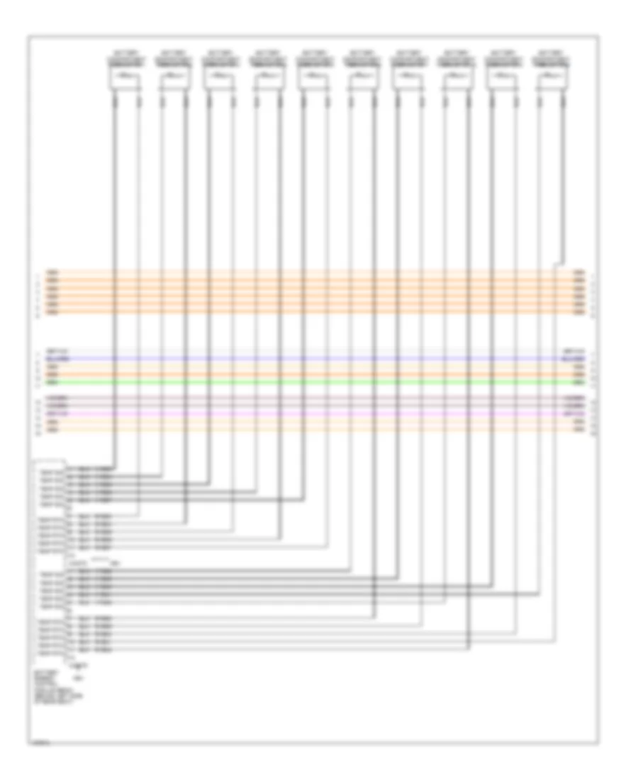
2.0L Hybrid, Engine Performance Wiring Diagram (7 of 10) for Ford Fusion Titanium 2014
List of elements for 2.0L Hybrid, Engine Performance Wiring Diagram (7 of 10) for Ford Fusion Titanium 2014:
- Battery compartment thermistor 1
- Battery compartment thermistor 10
- Battery compartment thermistor 2
- Battery compartment thermistor 3
- Battery compartment thermistor 4
- Battery compartment thermistor 5
- Battery compartment thermistor 6
- Battery compartment thermistor 7
- Battery compartment thermistor 8
- Battery compartment thermistor 9
- Battery energy control module (becm) (behind left side of rear seat)
- C4237c
- C4237d
- Hev
- Ryb33
- Ryb34
- Ryb35
- Ryb36
- Ryb37
- Ryb38
- Ryb39
- Ryb40
- Ryb41
- Ryb42
- Temp rtn
- Temp sig
- Vyb33
- Vyb34
- Vyb35
- Vyb36
- Vyb37
- Vyb38
- Vyb39
- Vyb40
- Vyb41
- Vyb42
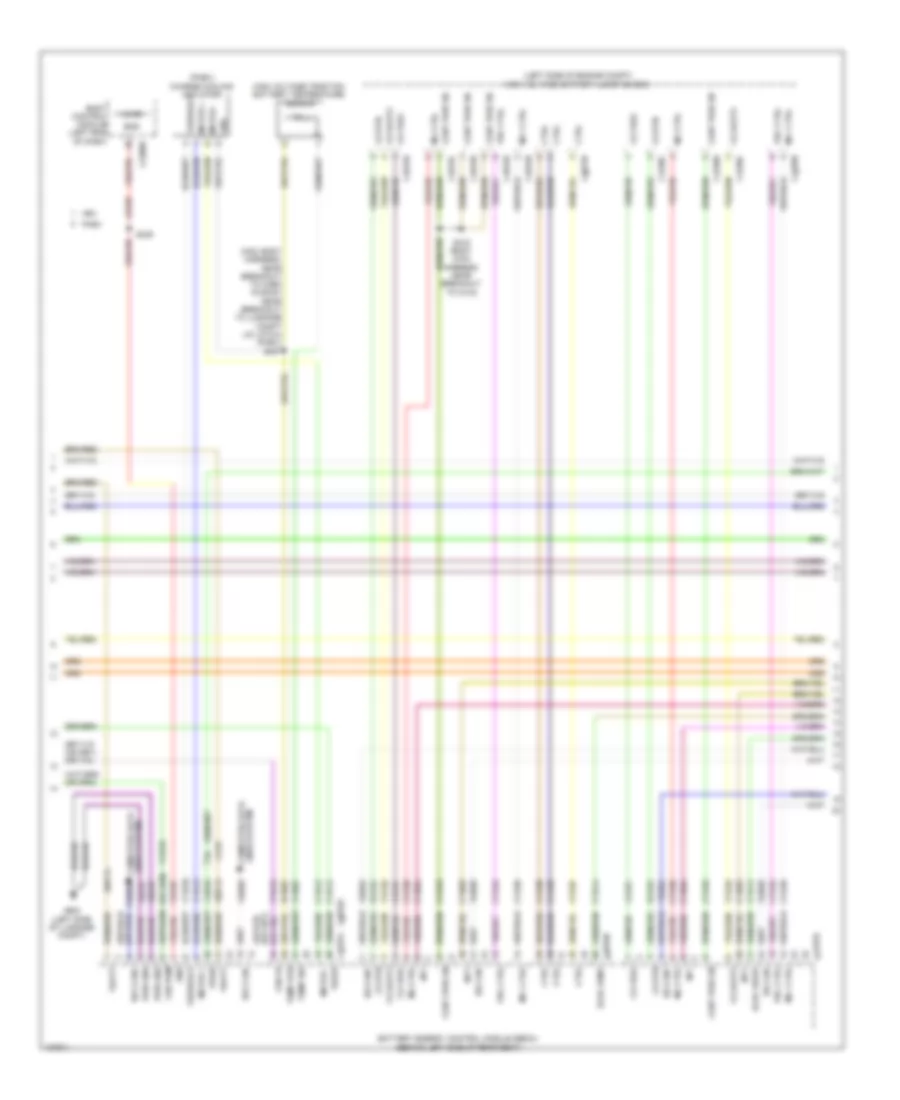
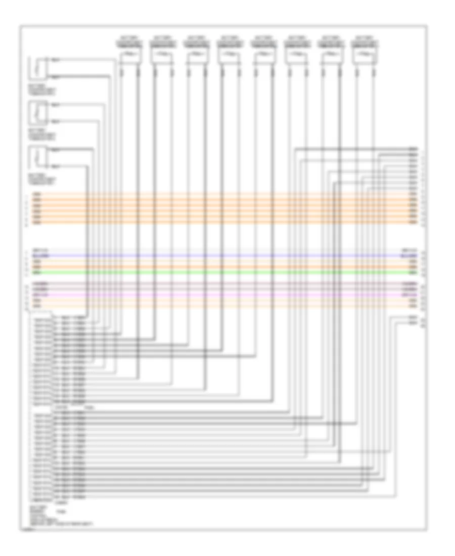
2.0L Hybrid, Engine Performance Wiring Diagram (8 of 10) for Ford Fusion Titanium 2014
List of elements for 2.0L Hybrid, Engine Performance Wiring Diagram (8 of 10) for Ford Fusion Titanium 2014:
- Battery compartment thermistor 1
- Battery compartment thermistor 10
- Battery compartment thermistor 11
- Battery compartment thermistor 2
- Battery compartment thermistor 3
- Battery compartment thermistor 4
- Battery compartment thermistor 5
- Battery compartment thermistor 6
- Battery compartment thermistor 7
- Battery compartment thermistor 8
- Battery compartment thermistor 9
- Battery energy control module (becm) (behind left side of rear seat)
- C4816c
- C4816d
- Phev
- Ryb33
- Ryb34
- Ryb35
- Ryb36
- Ryb37
- Ryb38
- Ryb39
- Ryb40
- Ryb41
- Ryb42
- Ryb43
- Ryb44
- Ryb45
- Ryb46
- Ryb47
- Ryb48
- Temp rtn
- Temp sig
- Vyb33
- Vyb34
- Vyb35
- Vyb36
- Vyb37
- Vyb38
- Vyb39
- Vyb40
- Vyb41
- Vyb42
- Vyb43
- Vyb44
- Vyb45
- Vyb46
- Vyb47
- Vyb48
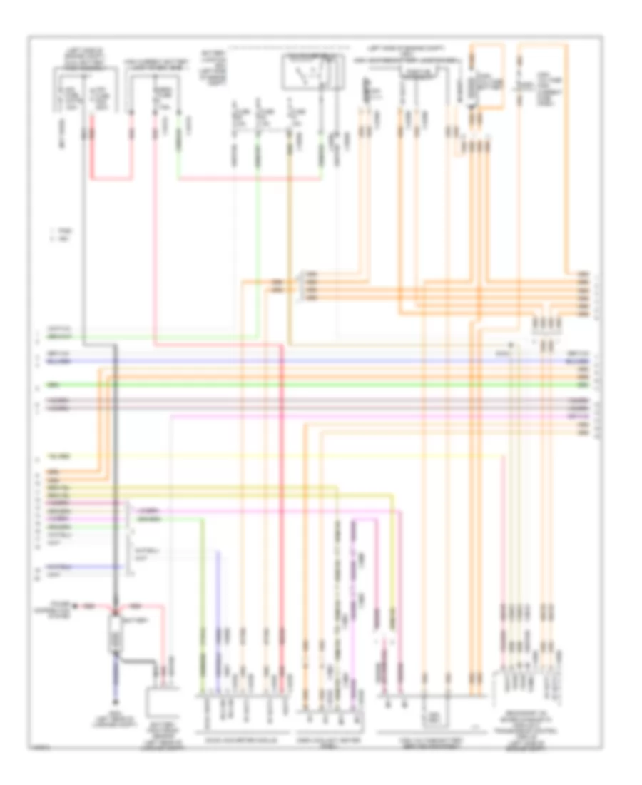
2.0L Hybrid, Engine Performance Wiring Diagram (9 of 10) for Ford Fusion Titanium 2014
List of elements for 2.0L Hybrid, Engine Performance Wiring Diagram (9 of 10) for Ford Fusion Titanium 2014:
- (exhaust manifold) universal heated oxygen sensor (ho2s) 11
- (left end of dash) body control module
- (on throttle body) electronic throttle control (etc) module
- (top center of cylinder head) cylinder head temperature sensor
- 30a
- Battery compartment thermistor 12
- Battery compartment thermistor 13
- Battery compartment thermistor 14
- Battery compartment thermistor 15
- C2280d
- C4815a
- C4815f
- C4815g
- C4815h
- C4815i
- Charge relay +
- Charge relay -
- Evaporative emission (evap) purge valve (left rear of engine)
- Heated oxygen sensor (ho2s) 12 (exhaust manifold)
- High voltage battery junction box (phev) (left side of engine compt)
- Hv batt-
- Lin 8
- Micro
- Nca
- Positive pack relay
- Pre charge relay
- Resistor 27 ohm
- Variable camshaft timing (vct11) solenoid 11 (top front of cylinder head)
- Vdn03
2.0L Hybrid, Engine Performance Wiring Diagram (10 of 10) for Ford Fusion Titanium 2014
List of elements for 2.0L Hybrid, Engine Performance Wiring Diagram (10 of 10) for Ford Fusion Titanium 2014:
- (left side of engine) manifold absolute pressure sensor
- (not used) c1026
- (on top of the engine, left of fuel injector 4 breakout)
- (top of engine)
- (top rear of engine) egr stepper motor
- Battery compartment thermistor 16
- C1026
- C175e
- Cabin heater coolant pump
- Ce101
- Ce102
- Ce103
- Ce104
- Ce113
- Ce205
- Ce206
- Ce207
- Ce208
- Ce233
- Ce235
- Ce347
- Ce412
- Ce420
- Ce421
- Ce426
- Ce622
- Ce908
- Ch307
- Cht
- Cmp08
- Coil 1
- Coil 2
- Coil 3
- Coil 4
- Cooling fans system
- Cto
- Digital
- Egrmc1
- Egrmc2
- Egrmc3
- Egrmc4
- Etcref
- Etcrtn
- Evapcp
- Evapldpsv
- Ffduc
- Fuel injector
- Ho2s12
- Htr12
- Iat
- Inj1
- Inj2
- Inj3
- Inj4
- Le134
- Le423
- Le448
- Le451
- Le452
- Lin
- Maf
- Map
- Mass air flow/intake air temperature (maf/iat) sensor (on throttle body)
- Oil pressure switch (oil filter housing)
- Ops
- Pasf+
- Powertrain control module (right rear of engine compt)
- Pwm
- Re134
- Re320
- Re329
- Re405
- Re406
- S120
- S147
- S153
- Sigrtn
- Tacm+
- Tacm-
- Tp1
- Tp2
- Transmissions system
- Trunk, tailgate, fuel doors system
- Uo2s11
- Uo2sgref11
- Uo2shtr11
- Uo2spc11
- Uo2spct11
- Vbv
- Vct11
- Vdn06
- Ve712
- Ve731
- Ve740
- Ve803
- Ve807
- Ve818
- Ve819
- Ve826
- Vmc02
- Vref
- Vref 5v
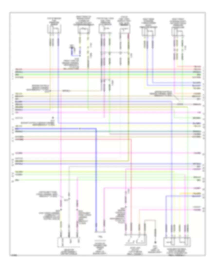
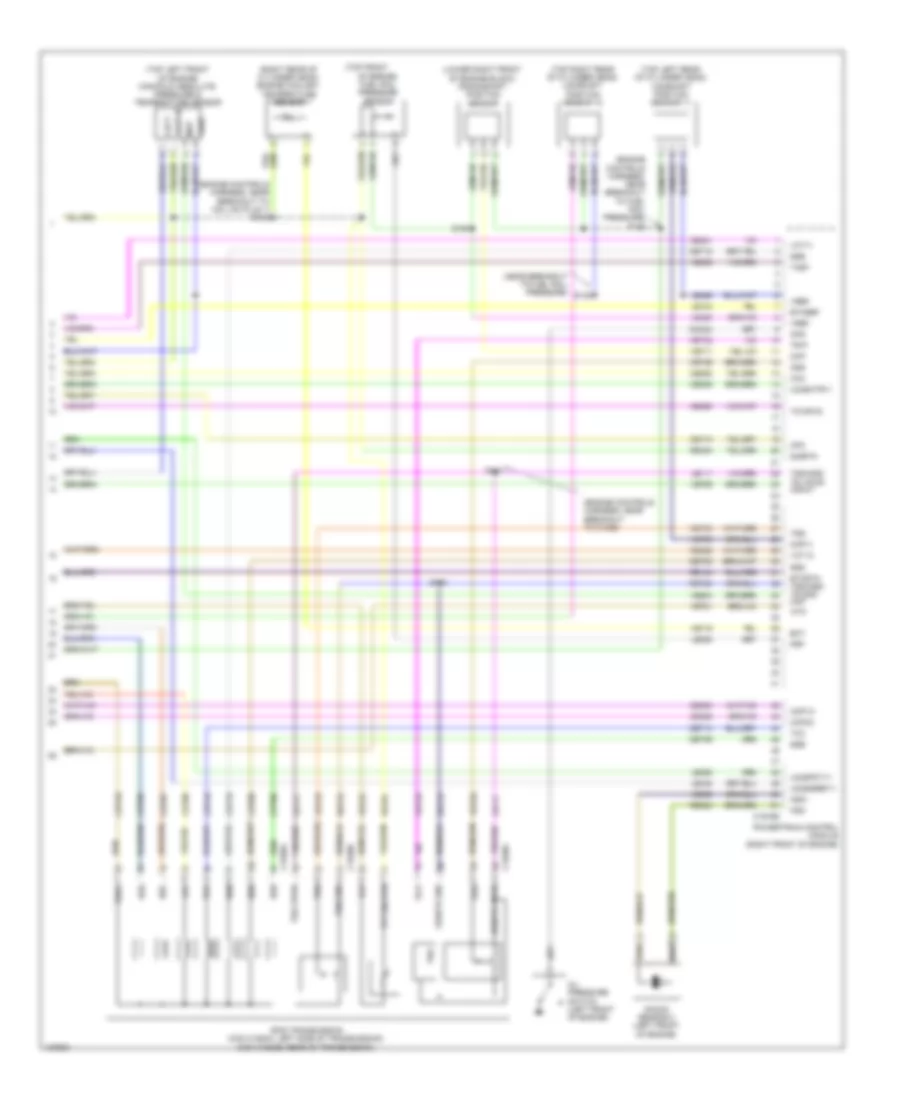
2.0L TURBO
2.0L Turbo, Engine Performance Wiring Diagram (1 of 6) for Ford Fusion Titanium 2014
List of elements for 2.0L Turbo, Engine Performance Wiring Diagram (1 of 6) for Ford Fusion Titanium 2014:
- (engine controls sensor harness, near breakout to anti-lock brake system module) s120
- 10a
- Accr
- Air conditioning system
- Apprtn1
- Apprtn2
- Appvref1
- Appvref2
- Awd-m
- Battery junction box (bjb) (left side of engine compt)
- C1010
- C1026
- C1035a
- C1381b
- C215
- C219
- C248
- C315
- Cact
- Can v
- Cbb26
- Cdc12
- Cdc15
- Cdc35
- Ce113
- Ce114
- Ce233
- Ce436
- Ce515
- Ce608
- Cec01
- Cec02
- Ch302
- Computer data lines system
- Cooling fans system
- Cr115
- Evapcp
- Fp pwr
- Fp rtn
- Fpc
- Fpm
- Fuel lvl2
- Fuel pump (fp) assembly (top of fuel tank)
- Fuel pump control module (left front of luggage compt)
- Fuel pump relay
- Fuel rtn
- Fuel sndr
- Fuse
- Fuse 10a
- Fuse 15a
- Fuse 20a
- Fuse 30a
- G304 (left "c" pillar)
- Gd304
- Genmon
- Gnd
- Hfc
- Hot at all times
- Hot in start or run
- Hs3 can +
- Hs3 can -
- Htr12
- Ies
- Instrument panel cluster (ipc) module
- Isp-r
- Le136
- Le137
- Le230
- Le423
- Le424
- Lfc
- Lin
- Nca
- Pcm power relay
- Pcm wake
- Powertrain control module (pcm) (right front of engine)
- Re136
- Re137
- Re230
- Re242
- Re332
- Re406
- Re407
- Re515
- Return
- S415
- S419
- Sig
- Sigrtn
- Smc
- Smr
- Starting/ charging system
- Transmissions system
- Vacc
- Vcf34
- Vdn06
- Ve225
- Ve462
- Ve518
- Vpwr
- Vref
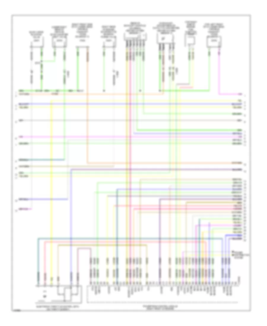
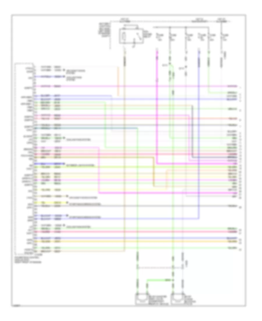
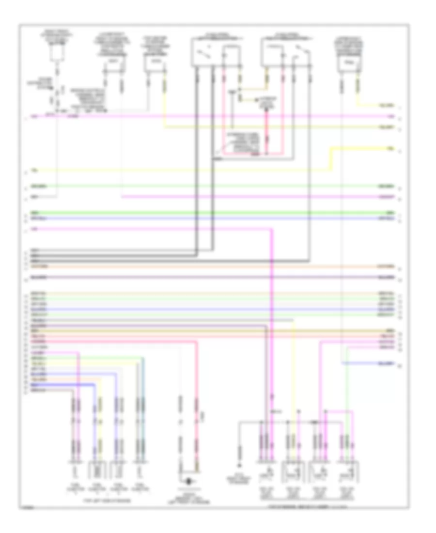
2.0L Turbo, Engine Performance Wiring Diagram (2 of 6) for Ford Fusion Titanium 2014
List of elements for 2.0L Turbo, Engine Performance Wiring Diagram (2 of 6) for Ford Fusion Titanium 2014:
- (engine controls sensor harness, near breakout to anti- lock brake system module)
- (engine controls sensor harness, near breakout to pcm)
- (engine controls sensor harness, near breakout to pcm) s134
- (instrument panel wiring harness, near breakout to g202)
- (right front of engine compt) air conditioning (a/c) pressure transducer
- (right front of engine compt) turbocharger boost pressure/charge air cooler temperature (tcbp/cact) sensor
- (top of engine) fuel pressure sensor
- (top of fuel tank) fuel level sensor
- (top of fuel tank) fuel tank pressure (ftp) sensor
- Accelerator pedal position (app) sensor (top of accelerator pedal assembly)
- C1010
- C145
- C218b
- C218c
- C2414a
- C2414d
- C315
- Cact
- Cet42
- Cet43
- Clockspring (behind steering wheel assembly)
- Computer data lines system
- G101 (left front of engine compt)
- Hs2 can+
- Hs2 can-
- Intake air temperature (iat) sensor (left front of engine compt)
- Nca
- Nca sst rtn
- Nca sst+
- Pnk
- Re407
- S119
- S131 (engine controls sensor harness, near breakout to pcm)
- S133
- S204
- S205
- S214
- S216
- Selector lever assembly (fusion) (center console)
- Sigrtn
- Sst-
- Steering column control module (sccm) (on steering column)
- Stop lamp switch (top of brake pedal assembly)
- Tcbp
- Vdb25
- Vdb26
- Vref
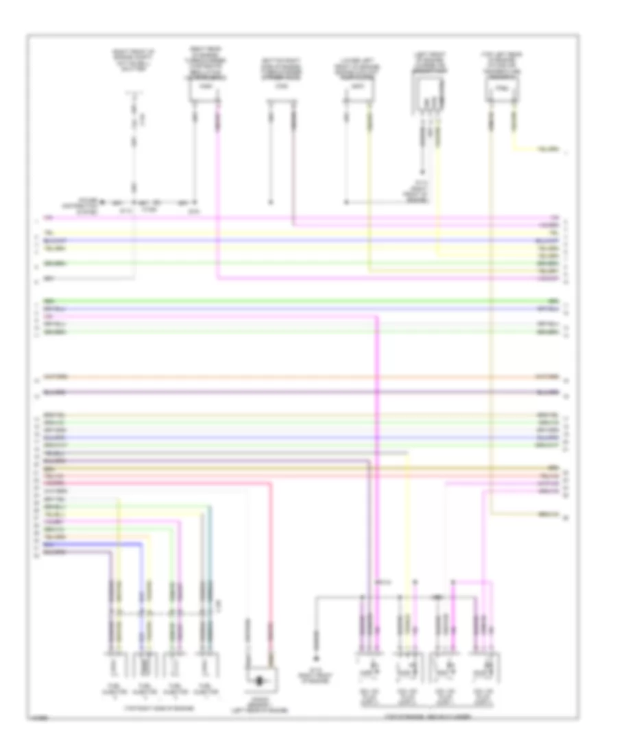
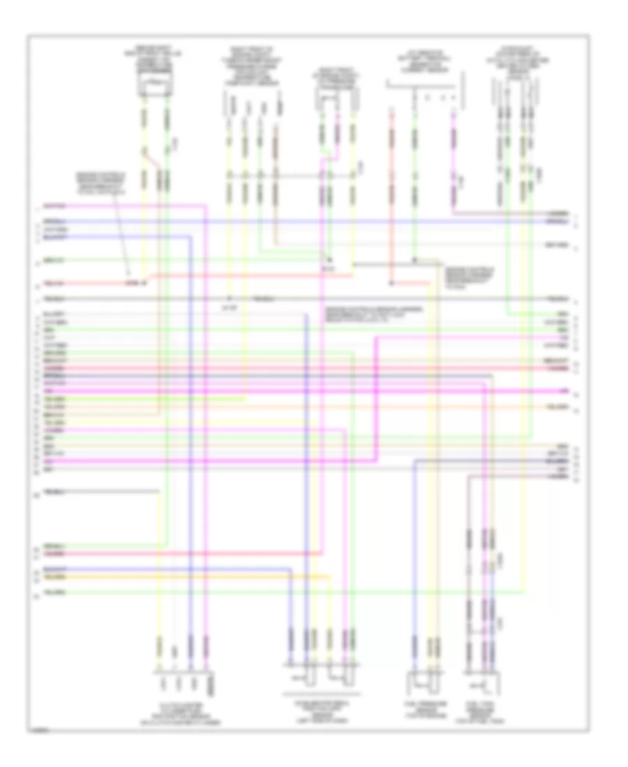
2.0L Turbo, Engine Performance Wiring Diagram (3 of 6) for Ford Fusion Titanium 2014
List of elements for 2.0L Turbo, Engine Performance Wiring Diagram (3 of 6) for Ford Fusion Titanium 2014:
- (behind right end of front grille) ambient air temperature (aat) sensor
- (engine controls sensor harness, near breakout to coil on plug 3) s126
- (not used)
- (on generator) generator current sensor
- Aat
- Acpt
- App1
- App2
- Awd-c
- Bcs2 alt
- Body control module (bcm) (left end of dash)
- Bpp
- Bps
- C134
- C1381b
- C146
- C1716f
- C219
- C2280a
- C2280b
- C2280c
- C2280h
- Cbb07
- Ccb08
- Cdc10
- Cdc54
- Ce237
- Ce420
- Ces09
- Cet42
- Cet43
- Computer data lines system
- Evap
- Flp
- Ftp
- Fuel pump (fet)
- Fuel pump on (fet)
- Fuse 5a
- G104 (right side of engine compt)
- Gd113
- Gear shift module (gsm) (upper center of dash)
- Gencom
- High current battery junction box (bjb) (left side of engine compt)
- Ho2s12
- Hot at all times
- Hs1 can+
- Hs1 can-
- Iat
- Mega fuse 125a
- Micro
- Nca
- Pcm rc
- Pcm wake up (fet)
- Powertrain control module (pcm) (right front of engine)
- Pwr 2
- Pwr gnd
- S112
- Smcs
- Sst+
- Sst-
- Starting/charging system
- Tcbp
- Transmissions system
- Vcf35
- Vdb04
- Vdb05
- Vdc61
- Ve701
- Ve702
- Ve727
- Ve731
- Ve740
- Ve750
- Ve805
- Ve922
- Vet77
- Vh433
- Vpwr
2.0L Turbo, Engine Performance Wiring Diagram (4 of 6) for Ford Fusion Titanium 2014
List of elements for 2.0L Turbo, Engine Performance Wiring Diagram (4 of 6) for Ford Fusion Titanium 2014:
- (engine controls harness, near breakout to coil on plug 1) s147
- (in exhaust, downstream of catalytic converter) heated oxygen sensor (ho2s) 12
- (not used)
- (not used) c1026
- (rear of engine) evaporative emission (evap) purge valve
- (rear of exhaust manifold) universal heated oxygen sensor (ho2s) 11
- (top front of cylinder head) variable camshaft timing 11 (vct11) solenoid
- (top front of cylinder head) variable camshaft timing 12 (vct12) solenoid
- (top rear of engine) fuel injection pump
- Atfpc
- Atfpm
- C1010
- C1026
- C1381e
- Ce205
- Ce206
- Ce207
- Ce208
- Ce226
- Ce304
- Ce305
- Ce412
- Ce426
- Cet05
- Cet07
- Cet09
- Cet49
- Cmp12
- Cop2d
- Cop3b
- Electronic throttle control (etc) (on throttle body)
- Evap canister purge valve
- Evap purge valve
- Fvr
- Fvrrtn
- Inj1
- Inj1rtn
- Inj2
- Inj2rtn
- Inj3
- Inj3rtn
- Inj4
- Inj4rtn
- Ks1+
- Ks1-
- Le451
- Lpc
- Nca
- Powertrain control module (pcm) (right front of engine)
- Re205
- Re206
- Re207
- Re208
- Re226
- Re323
- Re405
- S113
- S315
- Sigrtn
- Ssa
- Ssc
- Tacm+
- Tacm-
- Tft
- Tp1
- Tp2
- Tspc
- Uo2s11
- Uo2spc11
- Ve707
- Ve801
- Ve818
- Ve819
- Ve826
- Vet27
- Vyt11
- Vyt12
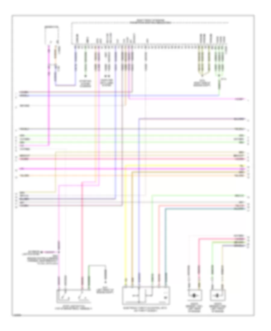
2.0L Turbo, Engine Performance Wiring Diagram (5 of 6) for Ford Fusion Titanium 2014
List of elements for 2.0L Turbo, Engine Performance Wiring Diagram (5 of 6) for Ford Fusion Titanium 2014:
- (engine controls harness, near breakout to crankshaft position sensor) s151
- (if equipped) left paddle shifter
- (if equipped) right paddle shifter
- (lower right front of engine) turbocharger (tc) wastegate regulating valve solenoid
- (right front of engine compt) active grill shutter
- (steering wheel horn wiring harness, near breakout to clockspring) s296
- (top center of engine) turbocharger bypass valve (tcby)
- (top left side of engine)
- (top of engine, above cylinder 1, 2, 3, & 4)
- (upper right side of engine) cylinder head temperature (cht) sensor
- C1026
- C1033
- C134
- Coil on plug (cop) 1
- Coil on plug (cop) 2
- Coil on plug (cop) 3
- Coil on plug (cop) 4
- Fuel injector
- G110 (right front of engine)
- Interior lights system
- Knock sensor 1 (ks1) (left front of engine)
- Nca
- Pnk
- Power distribution system
- S110
- S144
- S148
- S293
- S294
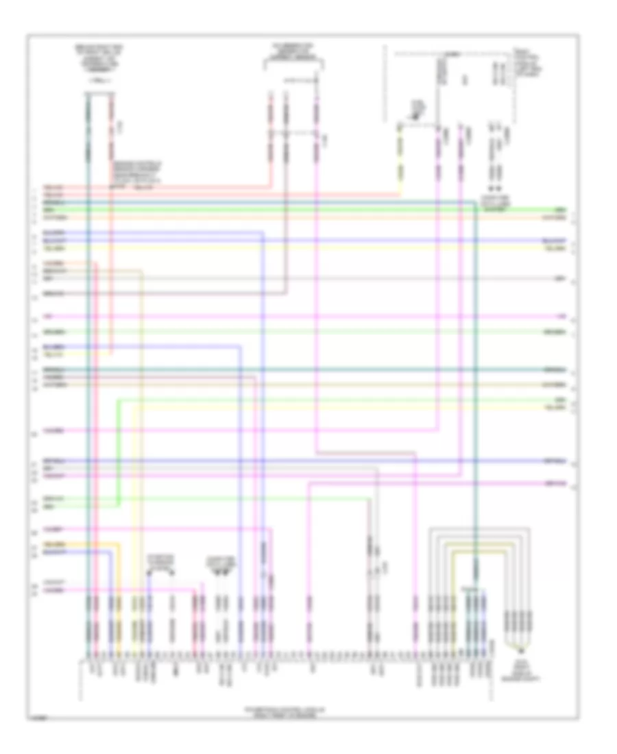
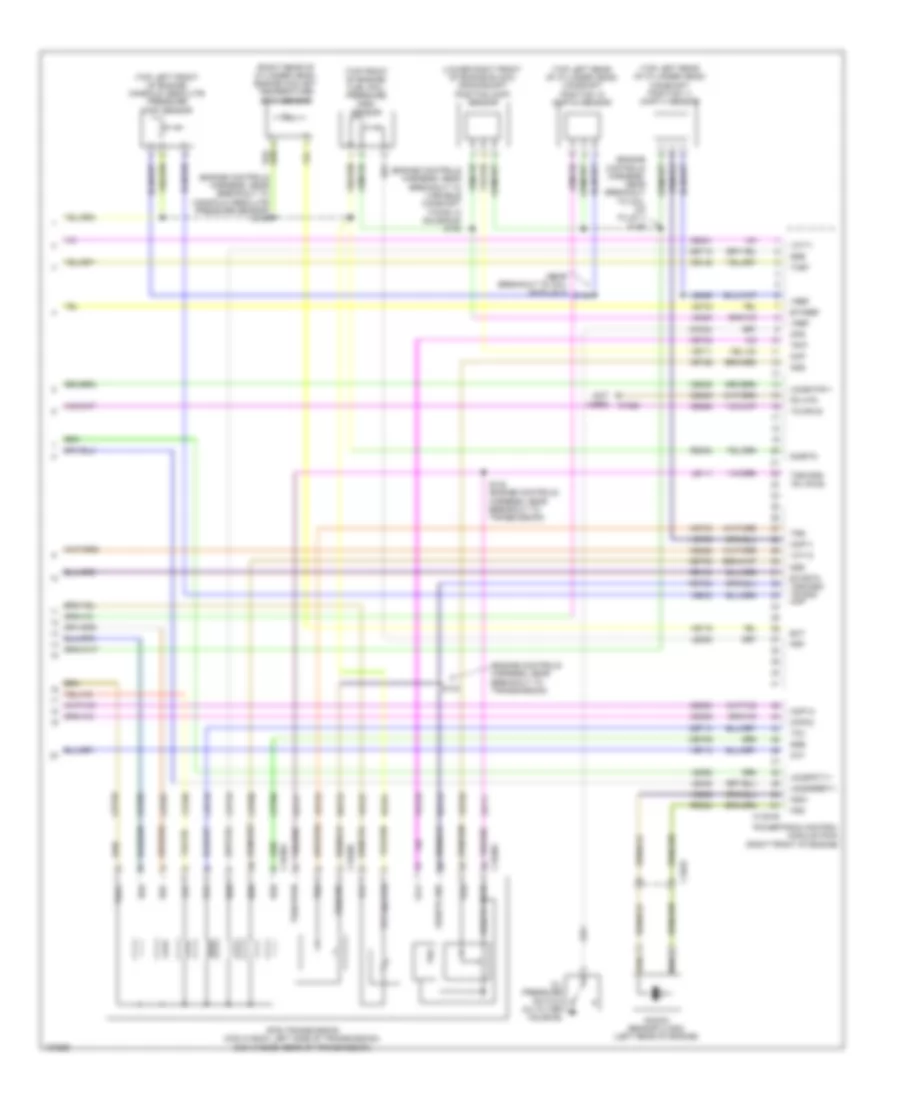
2.0L Turbo, Engine Performance Wiring Diagram (6 of 6) for Ford Fusion Titanium 2014
List of elements for 2.0L Turbo, Engine Performance Wiring Diagram (6 of 6) for Ford Fusion Titanium 2014:
- (engine controls harness, near breakout to coil on plug 1) s146
- (engine controls harness, near breakout to manifold absolute pressure sensor) s149
- (engine controls harness, near breakout to transmission)
- (engine controls harness, near breakout to variable camshaft timing 12 solenoid) s150
- (lower right front of engine block) crankshaft position (ckp) sensor
- (near breakout to coil on plug 4) s145
- (not used)
- (right rear of cylinder head) engine coolant temperature (ect) sensor
- (top front of engine) fuel rail pressure (frp) sensor
- (top left front of engine) manifold absolute pressure (map) sensor
- (top left rear of cylinder head) camshaft position 11 (cmp11) sensor
- (top left rear of cylinder head) camshaft position 12 (cmp12) sensor
- 6f35 transmission (con c1520a: left side of transmission) (con c1520b: rear of transmission)
- C1026
- C1033
- C1381e
- C1520a
- C1520b
- Ce148
- Ce235
- Ce239
- Ce303
- Ce306
- Ce421
- Ce422
- Ce460
- Cet05
- Cet06
- Cet07
- Cet08
- Cet09
- Cet10
- Cet18
- Cet49
- Cht
- Ckp
- Cmc24
- Cmp11
- Cop1a
- Cop4c
- Ect
- Etcref
- Etcrtn tss/oss/ tr gnd map
- Frp
- Knock sensor 2 (ks2) (left rear of engine)
- Ks2+
- Ks2-
- Le111
- Le134
- Le238
- Le423
- Le448
- Le452
- Le458
- Lpc
- Oil pressure switch (oil filter housing)
- Ops
- Oss
- Oss/tr gnd
- Oss/tr vpwr
- Pm htr
- Powertrain control module (pcm) (right front of engine)
- Re134
- Re324
- Re454
- Ret24
- S142 (engine controls harness, near breakout to transmission)
- S143
- Sigrtn
- Ssa
- Ssb
- Ssc
- Ssd
- Sse
- Tcby
- Tcc
- Tcwrvs
- Tft
- Tft sig rtn
- Tr-p
- Trs
- Tspc
- Tss
- Tss/gnd
- Tss/oss/ tr vpwr
- Tss/vpwr
- Uo2sgref11
- Uo2shtr11
- Uo2spct11
- Vct11
- Vct12
- Ve706
- Ve711
- Ve712
- Ve716
- Ve802
- Ve803
- Vet26
- Vet27
- Vet32
- Vet33
- Vref
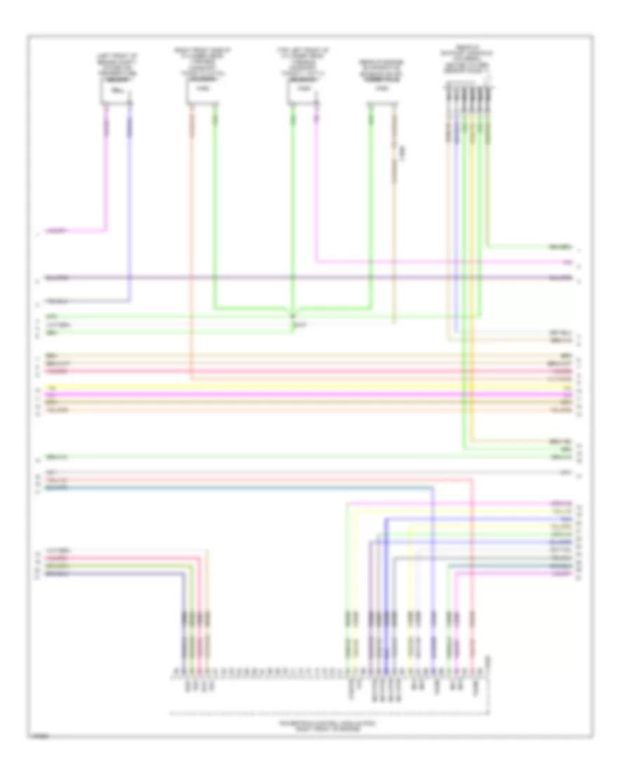
2.5L
2.5L, Engine Performance Wiring Diagram (1 of 5) for Ford Fusion Titanium 2014
List of elements for 2.5L, Engine Performance Wiring Diagram (1 of 5) for Ford Fusion Titanium 2014:
- (near breakout to coil on plug 3) s126
- 15a
- 20a
- Aat
- Accr
- Acpt
- Air conditioning pressure transducer (right front of engine compt)
- Air conditioning system
- Ambient air temperature sensor (behind right end of front grille)
- App1
- App2
- Apprtn1
- Apprtn2
- Appvref1
- Appvref2
- Battery junction box (bjb) (left side of engine compt)
- Bcs2 alt
- Bpp
- Bps
- C1010
- C1035a
- C134
- C145
- C146
- C1551b
- C219
- C2414a
- C315
- Canv
- Cbb07
- Cbb26
- Cbb49
- Ccb08
- Cdc10
- Cdc12
- Cdc15
- Cdc35
- Cdc54
- Ce114
- Ce237
- Ce436
- Cec01
- Cec02
- Ces09
- Cet42
- Cet43
- Ch302
- Computer data lines system
- Cooling fans system
- Cr115
- Fpc
- Fpm
- Fppwr
- Ftp
- Fuel tank pressure sensor (top of fuel tank)
- Fuse
- G104 (right side of engine compt)
- Gd113
- Gencom
- Generator current sensor (on generator)
- Genmon
- Hfc
- Hot at all times
- Hs can +
- Hs can -
- Iat
- Ies
- Isp r
- Le136
- Le137
- Le230
- Le423
- Lfc
- Lin
- Mafs
- Nca sst +
- Nca sst -
- Nca sst rtn
- Pcm power relay
- Pcm wake
- Pcmrc
- Power gnd
- Powertrain control module (pcm) (right front of engine)
- Re136
- Re137
- Re320
- Re407
- Ref
- S112
- S133 (near breakout to pcm)
- S205 (in breakout to steering column control module)
- Selector lever assembly (center console)
- Sigrtn
- Sigrtn a
- Smc
- Smcs
- Smr
- Sst +
- Sst -
- Starting/charging system
- Steering column control module (on steering column)
- Vdb04
- Vdb05
- Vdc61
- Vdn06
- Ve225
- Ve462
- Ve518
- Ve701
- Ve702
- Ve740
- Ve750
- Ve807
- Ve922
- Vh433
- Vpwr
- Vref
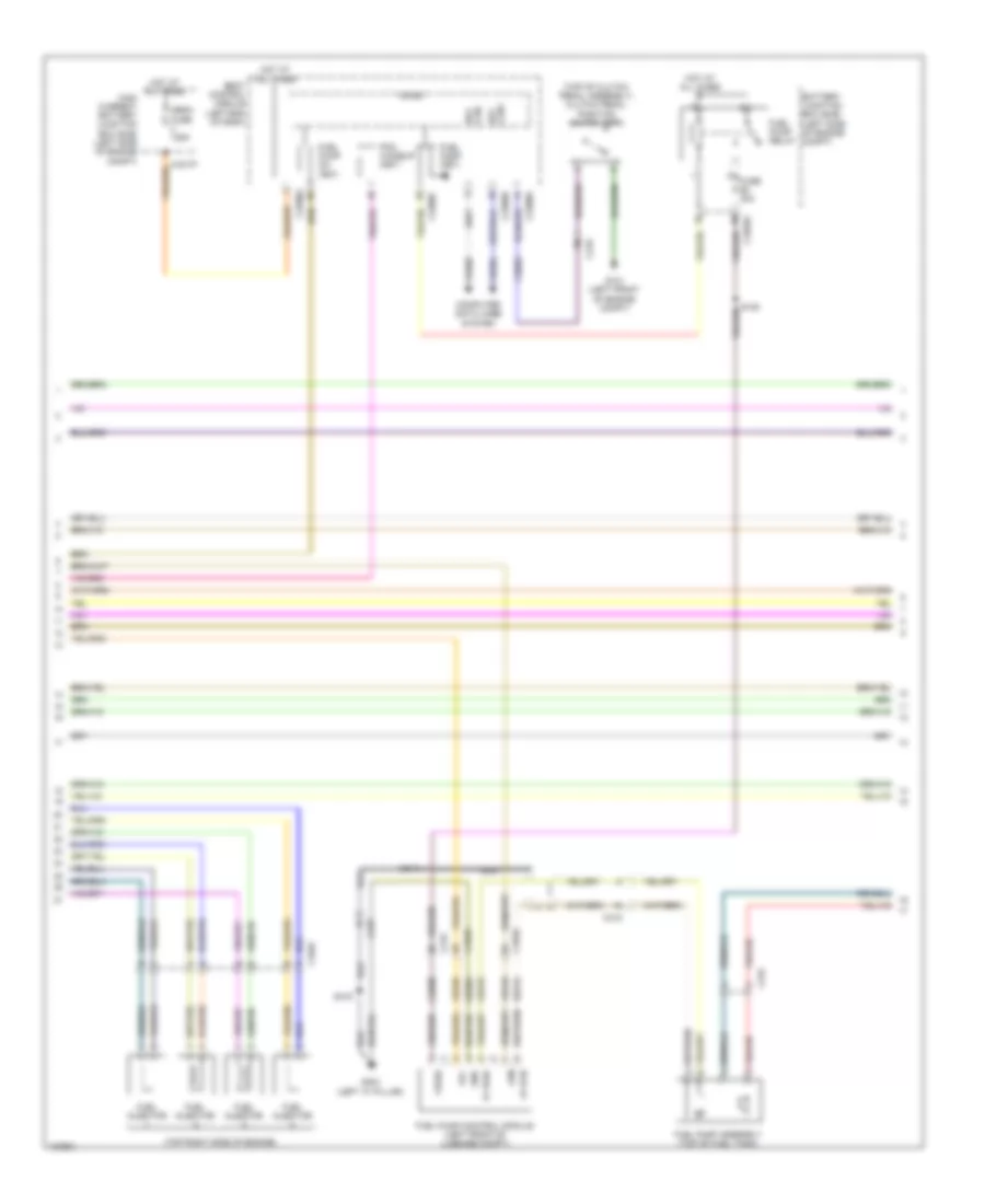
2.5L, Engine Performance Wiring Diagram (2 of 5) for Ford Fusion Titanium 2014
List of elements for 2.5L, Engine Performance Wiring Diagram (2 of 5) for Ford Fusion Titanium 2014:
- (under right rear of vehicle) evap canister vent control solenoid
- 10a
- 6f35 transmission (left side of transmission)
- Accelerator pedal position (app) sensor (left side of dash)
- Battery junction box (bjb) (left side of engine compt)
- Body control module (left end of dash)
- C1010
- C1035a
- C219
- C2280c
- C2280h
- Digital
- Fuel pump (fet)
- Fuel pump on (fet)
- Fuel pump relay
- Fuse
- Fuse 30a
- Fuse 5a
- Hot at all times
- Hot in start or run
- Lpc
- Mass air flow/ intake air temperature (maf/iat) sensor (left front of engine compt)
- Micro
- Oss
- Oss/tr gnd
- Oss/tr vpwr
- Pcm wake up (fet)
- Pcm wakeup sply
- S113
- S120
- S204 (near breakout to coil on plug 3)
- Ssa
- Ssb
- Ssc
- Ssd
- Sse
- Tcc
- Tft
- Tft sig rtn
- Tr-p
- Trs
- Tspc
- Vref 5v
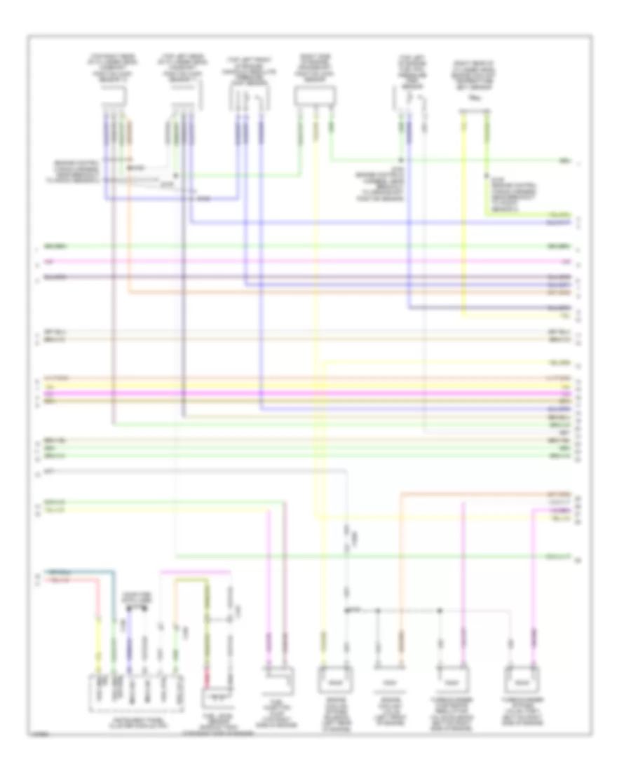
2.5L, Engine Performance Wiring Diagram (3 of 5) for Ford Fusion Titanium 2014
List of elements for 2.5L, Engine Performance Wiring Diagram (3 of 5) for Ford Fusion Titanium 2014:
- (in breakout to transmission)
- (in breakout to transmission) s141
- (left front of luggage compt) fuel pump control module
- (near breakout to fuel injector 1)
- (not used)
- (rear side of transmission) turbine shaft speed (tss) sensor
- (top of fuel tank) fuel pump assembly
- C1010
- C1026
- C1551t
- C215
- C248
- C315
- Ce225
- Ce233
- Ce515
- Ce608
- Cet05
- Cet06
- Cet07
- Cet08
- Cet09
- Cet10
- Cet18
- Cet25
- Cet34
- Computer data lines system
- Fpc
- Fpm
- Fppwr
- Fprtn
- Fuel sender return
- Fuel sender signal
- G304 (left "c" pillar)
- Gd304
- Gnd
- Heated oxygen sensor (ho2s) 12 (rear of exhaust manifold)
- Ho2s-12
- Hs3 can+
- Hs3 can-
- Htr-12
- Instrument panel cluster (ic) module
- Le111
- Lpc
- Nca
- Oss
- Powertrain control module (pcm)
- Re406
- Re515
- Ret24
- S142
- S156
- S415
- S419
- Sigrtnt
- Ssa
- Ssb
- Ssc
- Ssd
- Sse
- Tcc
- Tcs
- Tft
- Trs
- Trs/oss vpwr
- Tspc
- Tss
- Tss/oss/tr gnd
- Ve518
- Ve731
- Vet26
- Vet27
- Vet32
- Vet33
- Vper fuel
2.5L, Engine Performance Wiring Diagram (4 of 5) for Ford Fusion Titanium 2014
List of elements for 2.5L, Engine Performance Wiring Diagram (4 of 5) for Ford Fusion Titanium 2014:
- (front of engine) knock sensor
- (left rear of engine) evaporative emission (evap) purge valve
- (oil filter housing)
- (top rear of engine) egr stepper motor
- Coil
- Crankshaft position sensor (lower right front of engine block)
- Electronic throttle control (etc) motor (on throttle body)
- Exterior lights system
- G101 (left front of engine compt)
- Oil pressure switch
- S147
- S204
- Stop lamp switch (under left side of dash)
- Variable camshaft timing 11 (vct) solenoid (top front of cylinder head)
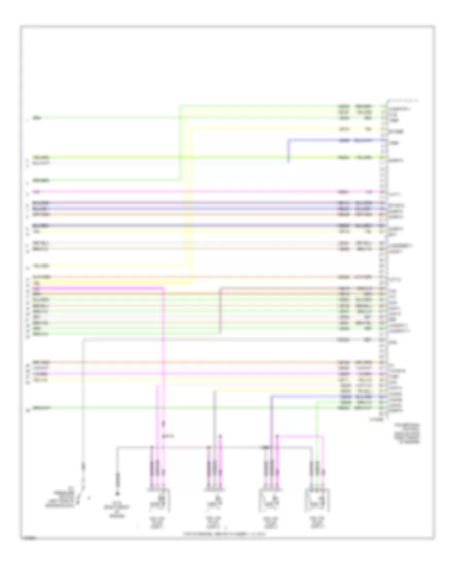
2.5L, Engine Performance Wiring Diagram (5 of 5) for Ford Fusion Titanium 2014
List of elements for 2.5L, Engine Performance Wiring Diagram (5 of 5) for Ford Fusion Titanium 2014:
- (left rear of engine) manifold absolute pressure (map) sensor
- (top of engine)
- (top of intake manifold) fuel injectors
- (upper right side of engine) cylinder head temperature sensor
- C1026
- C1551e
- Camshaft position 11 (cmp11) sensor
- Ce101
- Ce102
- Ce103
- Ce104
- Ce113
- Ce205
- Ce206
- Ce207
- Ce208
- Ce235
- Ce303
- Ce304
- Ce305
- Ce306
- Ce412
- Ce422
- Ce426
- Cht
- Cmc24
- Cmp 1
- Coil on plug (cop) 1
- Coil on plug (cop) 2
- Coil on plug (cop) 3
- Coil on plug (cop) 4
- Cop1a
- Cop2d
- Cop3b
- Cop4c
- Cpk+
- Cpk-
- De135
- Egrmc1
- Egrmc2
- Egrmc3
- Egrmc4
- Etcref
- Etcrtn
- Evapcp
- Ignition transformer capacitor (top rear of engine)
- Inj1
- Inj2
- Inj3
- Inj4
- Ks1+
- Ks1-
- Le111
- Le134
- Le423
- Le448
- Le451
- Map
- Ops
- Powertrain control module (pcm)
- Re134
- Re135
- Re323
- Re405
- S144
- S146
- S153 (near breakout to fuel injector 2)
- Shdrtn
- Sigrtn
- Tacm+
- Tacm-
- Tp2
- Tps1
- Universal heated oxygen sensor (ho2s) 11 (rear of exhaust manifold)
- Uo2s11
- Uo2sgref 11
- Uo2shtr 11
- Uo2spc 11
- Vct 11
- Ve706
- Ve711
- Ve712
- Ve801
- Ve803
- Ve818
- Ve819
- Ve826
- Vref