ENGINE PERFORMANCE
3.8L
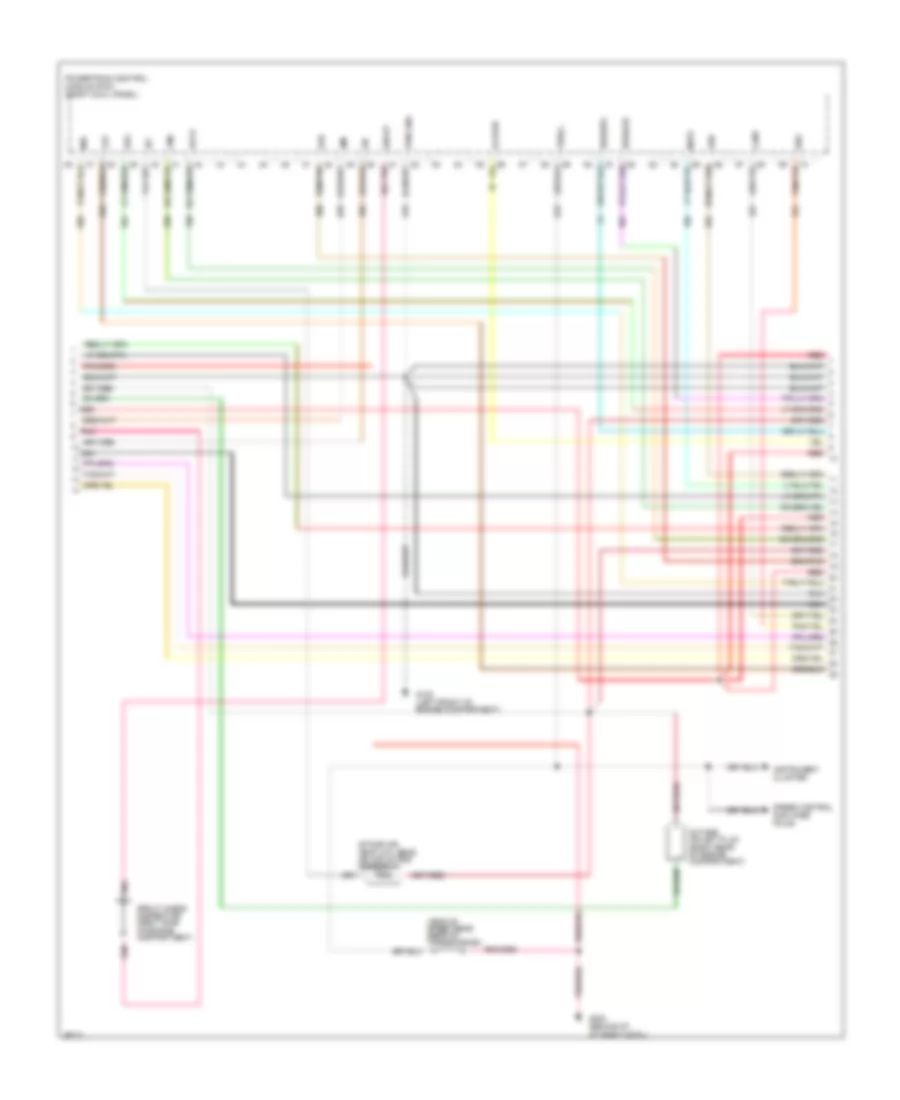
3.8L, Engine Performance Wiring Diagrams (1 of 6) for Ford Mustang 1995

List of elements for 3.8L, Engine Performance Wiring Diagrams (1 of 6) for Ford Mustang 1995:
- C 1995 vftc
- C250
- C251
- Ckp(+)
- Ckp(-)
- Crankshaft position sensor (center front of engine)
- Cse gnd
- Data link connector (behind i/p, right
- Data link connector (right rear of
- Dlc
- Dlc(+)
- Dlc(-)
- Engine compartment)
- Fuse 10a
- Fuse 20a
- G100 (left front of engine compartment)
- G203 (behind i/p at right cowl)
- G206 (behind center of i/p)
- Gnd
- Hfc
- Ho2s(rr)
- Hot at all times
- Hot in run or start
- I/p fuse panel
- Idm
- Ign coil
- Ign gnd
- Ignition coil (top front of engine)
- Ignition control module (right front apron)
- Instrument cluster
- L. spd edf mntr 10a
- Malfunction indicator
- Mil
- Nca
- Of steering column)
- Pip
- Pnk
- Powertrain control module (pcm) (right cowl panel)
- Pwr
- Pwr gnd
- Radio interference capacitor (top right front of engine)
- Red
- Shield
- Spark plugs
- Spout
- Ss1
- Ss2
- Tach
- Tcs
- Vss(-)
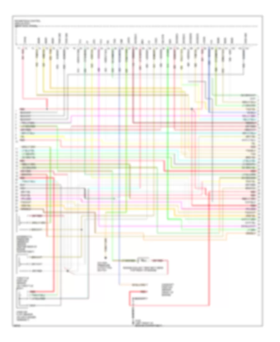
3.8L, Engine Performance Wiring Diagrams (2 of 6) for Ford Mustang 1995
List of elements for 3.8L, Engine Performance Wiring Diagrams (2 of 6) for Ford Mustang 1995:
- Accs
- Canp
- Ecs
- Egr
- Evr
- Fpm
- G100 (left front of engine compartment)
- G203 (behind i/p, at right cowl)
- Ho2s(lr)
- Ho2s(rf)
- Iat
- Idm
- Instrument cluster
- Intake air temp (iat) sens (on air intake assembly)
- Ka pwr
- Maf
- Mlps
- Nca
- Octane adjust plug (right rear of engine compartment)
- Pip
- Pnk
- Powertrain control module (pcm) (right cowl panel)
- Pwr gnd
- Red
- Speed control amplifier pin #3
- Spout
- Spout check connector (right side of engine compartment)
- Tot
- Vehicle speed sens (rear of transmission)
- Vss(+)
- Wac
3.8L, Engine Performance Wiring Diagrams (3 of 6) for Ford Mustang 1995
List of elements for 3.8L, Engine Performance Wiring Diagrams (3 of 6) for Ford Mustang 1995:
- (front of engine)
- (on air cleaner assembly)
- (on throttle body)
- (top front of engine)
- A/c high pressure cutout fan switch
- Ahps
- Boo
- Camshaft position sensor
- Cmp
- Differential pressure feedback sensor (center rear of engine compartment)
- Engine coolant temp (ect) sens
- Epc
- G100 (left front of engine compartment)
- Ho2s(lf)
- Ho2s(lr)
- Ho2s(rf)
- Ho2s(rr)
- Iac
- Inj#1
- Inj#2
- Inj#3
- Inj#4
- Inj#5
- Inj#6
- Lfc
- Maf
- Mass air flow sensor
- Nca
- Powertrain control module (pcm) (right cowl panel)
- Pwr gnd
- Red
- Sig rtn
- Tan
- Tcc
- Tcl
- Throttle position sensor
- Tss
- Vpwr
- Vref
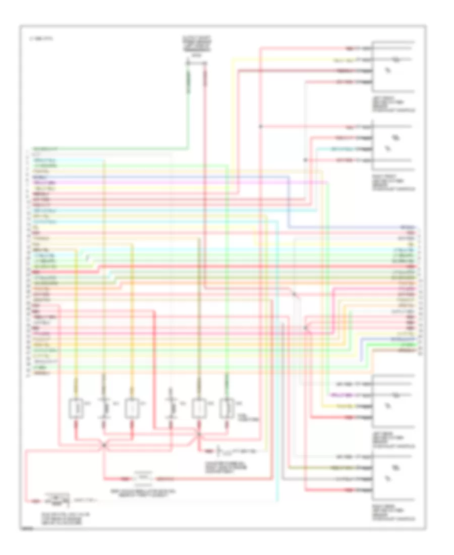
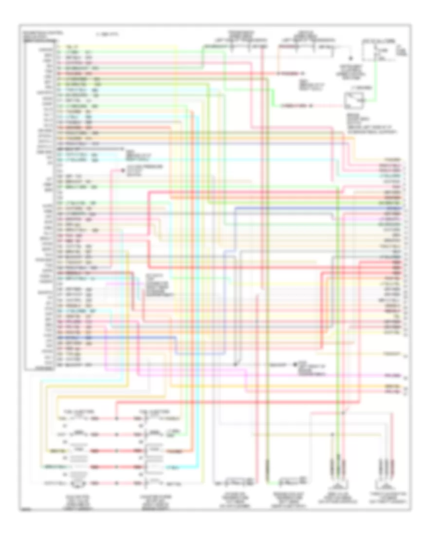
3.8L, Engine Performance Wiring Diagrams (4 of 6) for Ford Mustang 1995
List of elements for 3.8L, Engine Performance Wiring Diagrams (4 of 6) for Ford Mustang 1995:
- # 1
- # 2
- # 3
- # 4
- # 5
- # 6
- (rear of throttle body)
- C 1995 vftc
- Canister purge sol (right side of engine compartment)
- Egr vacuum regulator (evr) sol
- Fuel injectors
- Idle air ctrl (iac) valve (top rear of engine above valve cover)
- Left front heated oxygen sensor (in exhaust manifold)
- Left rear heated oxygen sensor (in exhaust manifold)
- Nca
- Output shaft speed sensor (left side of transmission)
- Red
- Right front heated oxygen sensor (in exhaust manifold)
- Right rear heated oxygen sensor (in exhaust manifold)
- Tan
3.8L, Engine Performance Wiring Diagrams (5 of 6) for Ford Mustang 1995
List of elements for 3.8L, Engine Performance Wiring Diagrams (5 of 6) for Ford Mustang 1995:
- (below rear of center console)
- A/c clutch
- A/c compressor clutch
- A/c high pressure cutout fan switch
- A/t only
- Constant control relay module (mounted on bracket behind engine coolant reservoir)
- Control
- Cooling fans system
- Edf relay
- Edf relay control
- Eec fuse 20a
- Engine compartment fuse box
- Fan fuse 60a
- Fuel pump (on fuel tank)
- Fuel pump fuse 20a
- Fuel pump relay
- Fuse 20a
- G100 (left front of engine compartment)
- G302
- Hedf relay (not used)
- Hot at all times
- Hot in run or start
- I/p fuse panel
- Inertia fuel shut off sw (left rear of trunk)
- Manual lever position sensor (rear left side of transmission)
- Pcm power relay
- Red
- Solid state
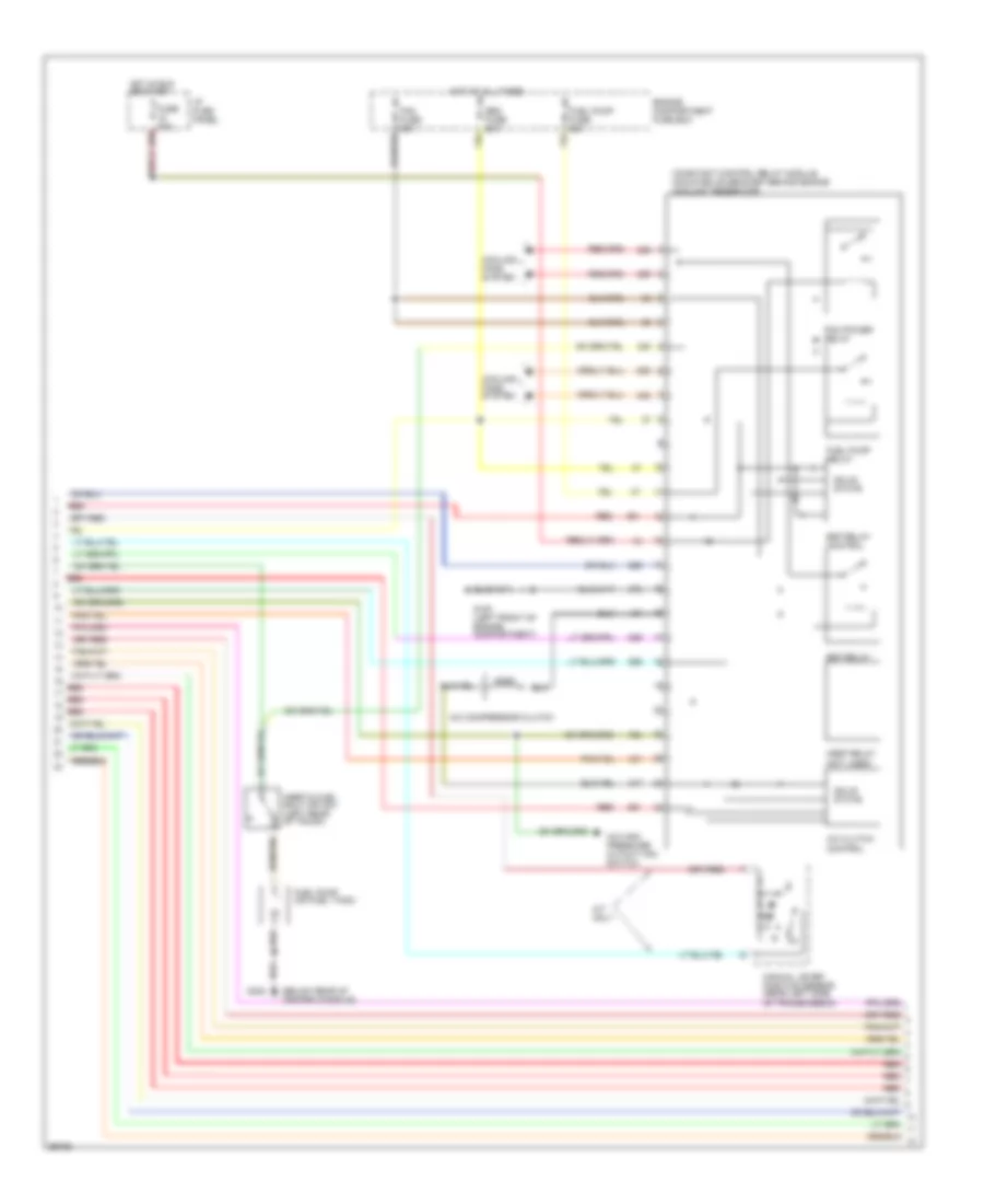
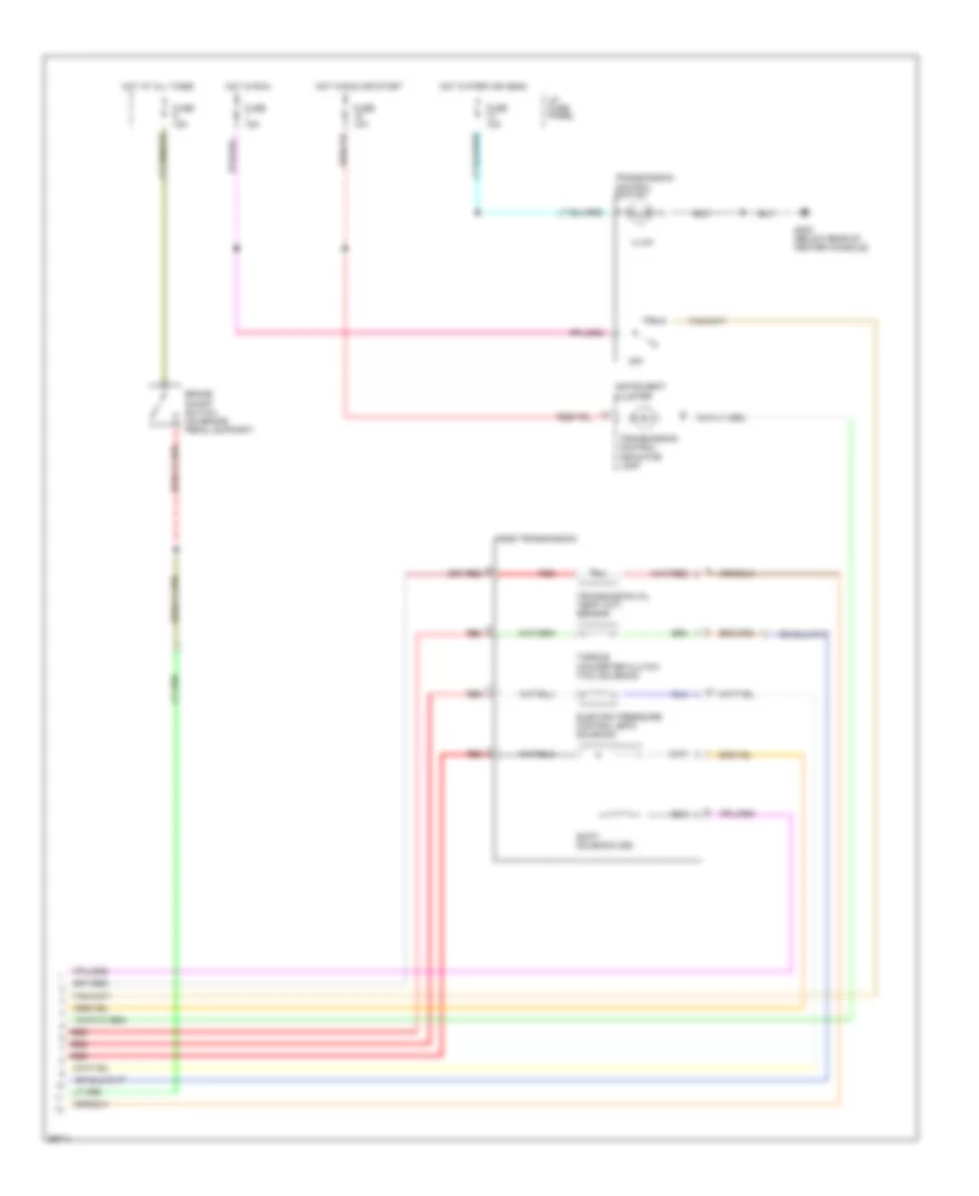
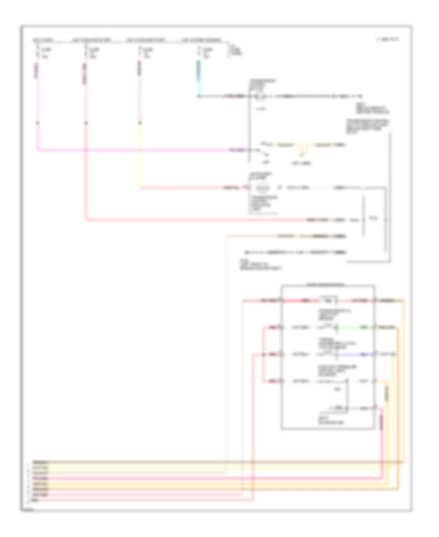
3.8L, Engine Performance Wiring Diagrams (6 of 6) for Ford Mustang 1995
List of elements for 3.8L, Engine Performance Wiring Diagrams (6 of 6) for Ford Mustang 1995:
- Aode transmission
- Brake on/off switch (on brake pedal support)
- Electric pressure control (epc) solenoid
- Fuse 10a
- Fuse 15a
- G302 (below rear of center console)
- Hot at all times
- Hot in park or head
- Hot in run
- Hot in run or start
- I/p fuse panel
- Illum
- Instrument cluster
- Off
- Red
- Shift solenoid (ss)
- Torque converter clutch (tcc) solenoid
- Transmission control indicator lamp
- Transmission control switch
- Transmission oil temp (tot) sensor
5.0L
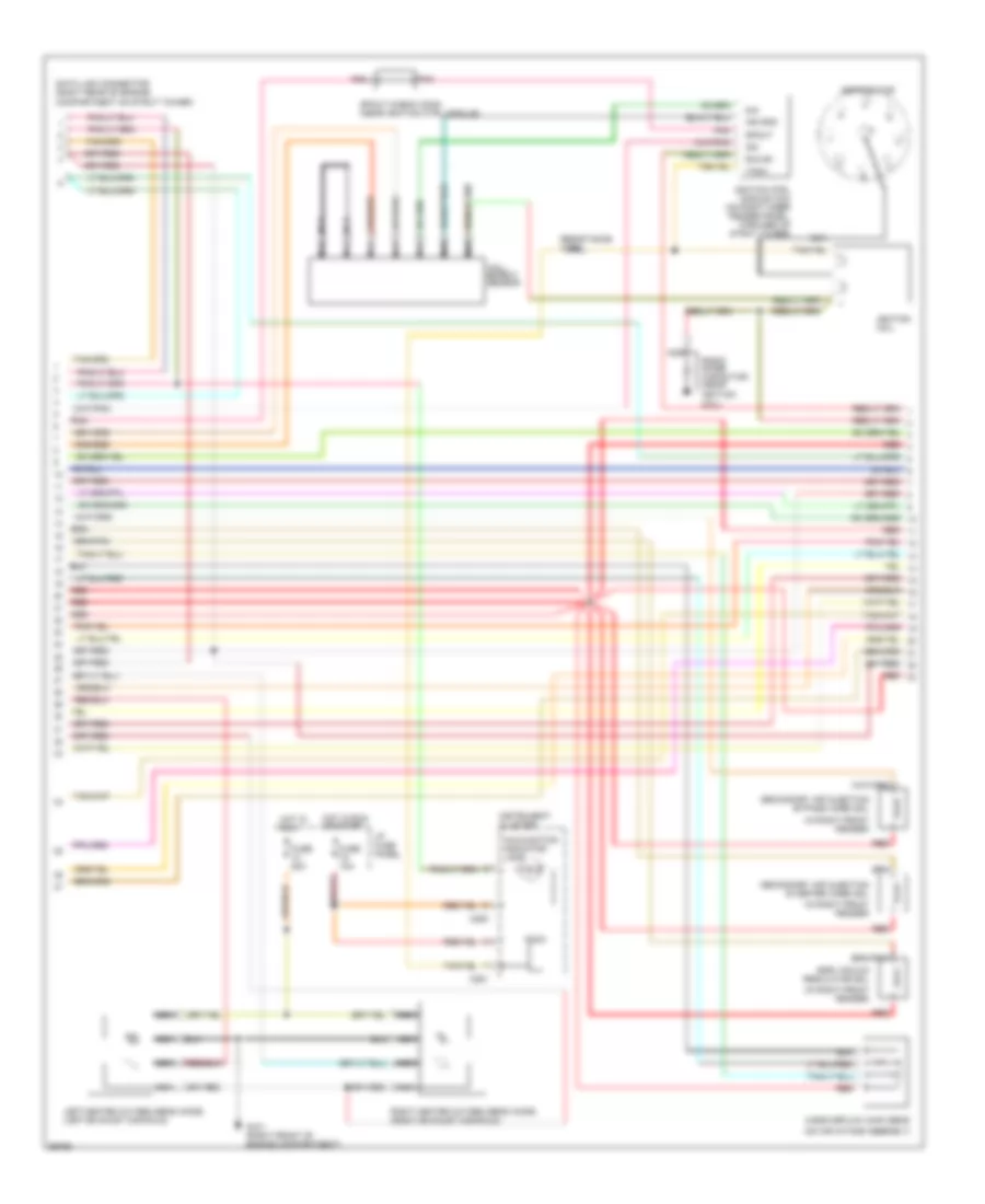
5.0L, Engine Performance Wiring Diagrams (1 of 4) for Ford Mustang 1995
List of elements for 5.0L, Engine Performance Wiring Diagrams (1 of 4) for Ford Mustang 1995:
- (behind left side of i/p
- (left rear of transmission)
- A/c high pressure cut-out switch
- Accs
- Acps
- Airb
- Aird
- Boo
- Brake on/off (boo) switch
- C 1995 vftc
- Canister purge (evap) sol (right side of engine compt)
- Canp
- Cse gnd
- Data (+)
- Data (-)
- Ecpo
- Ect
- Egr
- Egr valve position sens (on intake manifold)
- Engine coolant temperature (ect) sens (near injector #1)
- Evr
- Fpm
- Fuel injectors
- Fuse 15a
- G100 left front of engine compartment)
- G203 (behind i/p at right cowl)
- Hfc
- Ho2s-l
- Ho2s-r
- Hot at all times
- I/p fuse panel
- Iac
- Iat
- Idle air ctrl (iac) valve (forward of throttle body)
- Idm
- Ign gnd
- Inj 4
- Inj 5
- Inj 6
- Inj 7
- Inj 8
- Inj1
- Inj2
- Inj3
- Instrument cluster & speed control amplifier
- Intake air temperature (iat) sens (on air cleaner)
- Kapwr
- Lfc
- Maf
- Maf rtn
- Mlps
- On brake pedal support)
- Ots
- Pip
- Pnk
- Powertrain control module (pcm) (right cowl panel)
- Pwr gnd
- Red
- Sig rtn
- Spout
- Ss1
- Ss2
- Sti
- Sti data link connector (right rear of engine compartment)
- Sto/mil
- Tan
- Tan/red
- Tcc
- Tcs
- Throttle position (tp) sens (on throttle body)
- Transmission speed sens (left side of transmission)
- Tss
- Vehicle speed sens
- Vpwr
- Vref
- Vss+
- Vss-
- Wac
5.0L, Engine Performance Wiring Diagrams (2 of 4) for Ford Mustang 1995
List of elements for 5.0L, Engine Performance Wiring Diagrams (2 of 4) for Ford Mustang 1995:
- (in right front fender)
- (on air intake assembly)
- C250
- C251
- Coil)
- Data link connector (right rear of engine compartment on strut tower)
- Distributor
- Egr vacuum regulator sol
- Fuse 10a
- Fuse 20a
- G101 (right front of engine compartment)
- Hall effect sensor
- Hot in run
- Hot in run or start
- I/p fuse panel
- Idm
- Ignition coil
- Ignition ctrl module (icm) (on right inner fender panel, forward of strut tower)
- Ind gnd
- Instrument cluster
- Left heated oxygen sens (ho2s) (left exhaust manifold)
- Malfunction indicator lamp
- Mass airflow (maf) sens
- Nca
- Pip
- Pnk
- Radio noise capacitor (near ignition
- Red
- Resistance wire
- Right heated oxygen sens (ho2s) (right exhaust manifold)
- Run b+
- Secondary air injection bypass (airb) sol
- Secondary air injection diverter (airb) sol
- Spout
- Spout check conn (near ignition ctrl module)
- Tach
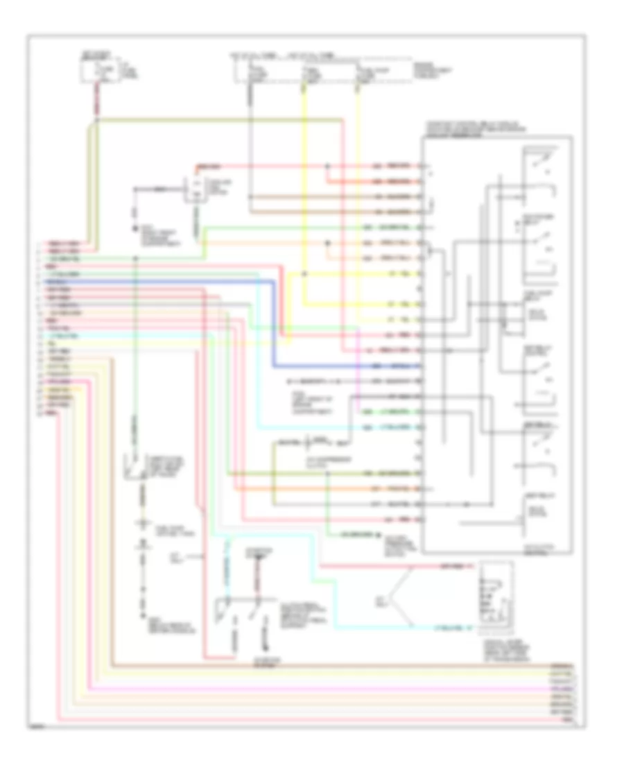
5.0L, Engine Performance Wiring Diagrams (3 of 4) for Ford Mustang 1995
List of elements for 5.0L, Engine Performance Wiring Diagrams (3 of 4) for Ford Mustang 1995:
- A/c clutch
- A/c compressor clutch
- A/c high pressure cutout fan switch
- A/t only
- Clutch pedal position switch (behind i/p on clutch pedal support)
- Compartment)
- Constant control relay module (mounted on bracket behind engine coolant reservoir)
- Control
- Cooling fan motor
- Edf relay
- Edf relay control
- Eec fuse 20a
- Engine compartment fuse box
- Fan fuse 60a
- Fuel pump (on fuel tank)
- Fuel pump fuse 20a
- Fuel pump relay
- Fuse 20a
- G100 (left front of engine
- G101 (right front of engine compartment)
- G302 (below rear of center console)
- Hedf relay
- Hot at all times
- Hot in run or start
- I/p fuse panel
- Inertia fuel shut off sw (left rear of trunk)
- M/t only
- Manual lever position sensor (rear left side of transmission)
- Pcm power relay
- Red
- Solid state
- Starting system
5.0L, Engine Performance Wiring Diagrams (4 of 4) for Ford Mustang 1995
List of elements for 5.0L, Engine Performance Wiring Diagrams (4 of 4) for Ford Mustang 1995:
- (not used)
- Aode transmission
- C 1995 vftc
- Electric pressure control (epc) solenoid
- Fuse 10a
- Fuse 15a
- Fuse 20a
- G100 (left front of engine compartment)
- G302 (below rear of center console)
- Hot in park or head
- Hot in run
- Hot in run or start
- I/p fuse panel
- Illum
- Instrument cluster
- Nca
- Off
- Red
- Shift solenoid (ss)
- Ss1
- Ss2
- Torque converter clutch (tcc) solenoid
- Transmission control indicator lamp
- Transmission control switch
- Transmission control switch module (tcsm) (behind right side of i/p)
- Transmission oil temp (tot) sensor