ENGINE PERFORMANCE
2.3L
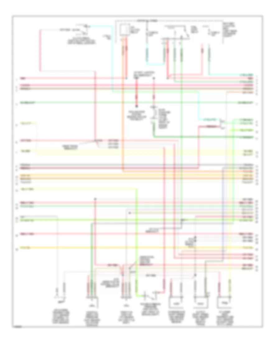
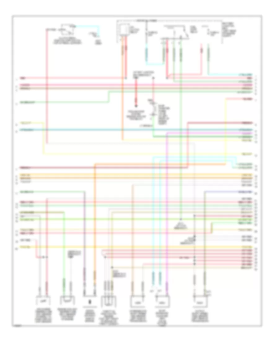
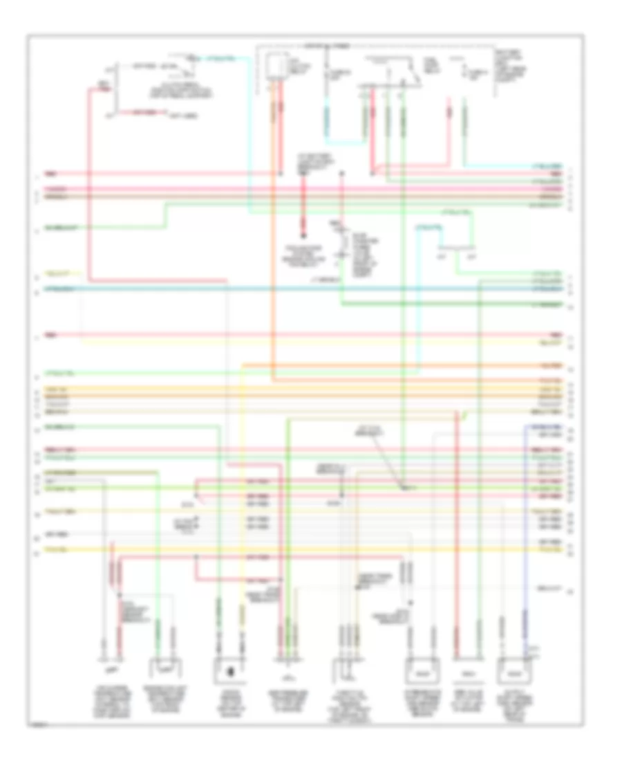
2.3L, Engine Performance Wiring Diagram (1 of 4) for Ford Ranger 2004

List of elements for 2.3L, Engine Performance Wiring Diagram (1 of 4) for Ford Ranger 2004:
- (at bottom of steering column)
- (left front of engine compt)
- A/c demand sig
- A/c system
- Act sens in
- Anti-theft ind
- Anti-theft system
- Battery junction box (left rear of engine compt)
- C220b
- C251
- Ccs
- Ckp sens +
- Ckp sens -
- Cool fan rly
- Cooling fans system
- Crankshaft position (ckp) sensor (on lower right front of engine)
- Data link connector (dlc)
- Digital transmission range (dtr) sensor (left side of transmission)
- Fail safe cool in
- Fuel pump rly
- Fuel pump/gauge
- Fuse 11 30a
- G104
- G106 (top rear of engine compt)
- Gnd
- Ho2s 11 in
- Hot at all times
- Hot in run or start
- Ignition coil
- Ignition coil (on top right side of engine)
- Instrument cluster
- Knock sens
- Knock sensor (left front of engine)
- Maf sig
- Malfunction indicator lamp (mil)
- Microprocessor
- Mil
- Mod prog sig
- Nca
- Pcm power diode
- Pcm power relay
- Powertrain control module (pcm) (right rear of engine compt, through firewall)
- Psp sw
- Ptc 1a
- Red
- Rx sig
- S107
- S118
- S145
- Scp bus+
- Scp bus-
- Sensor tr1
- Sensor tr2
- Sensor tr4
- Shift sol a
- Shift sol b
- Smart junction box (behind right side of dash)
- Start rly cntl
- Starting system
- Tachometer
- Tft sens in
- Trans cntl sw
- Tss
- Tx sig
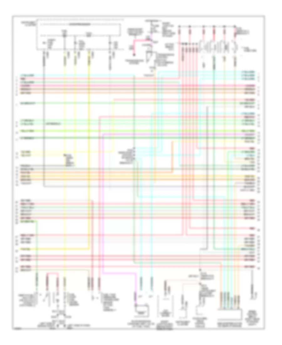
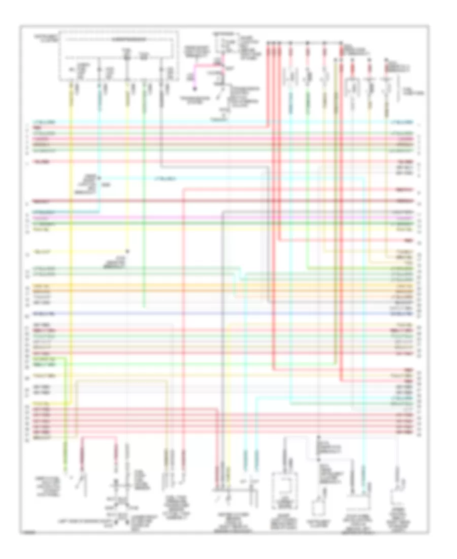
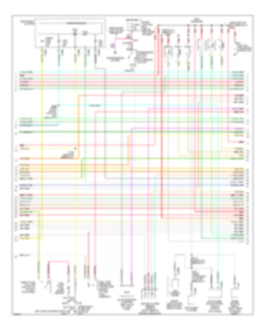
2.3L, Engine Performance Wiring Diagram (2 of 4) for Ford Ranger 2004
List of elements for 2.3L, Engine Performance Wiring Diagram (2 of 4) for Ford Ranger 2004:
- (at bat junction box breakout) s113
- (at c144 breakout)
- (near swirl control monitor breakout)
- (near trans breakout)
- A/c clutch relay
- A/t
- Air charge temperature (act) sensor (integral to mass airflow (maf) sensor)
- Battery junction box (left rear of engine compt)
- Clutch pedal position (cpp) switch (top of pedal support)
- Cooling fans system (engine cooling fan relay)
- Cylinder head temperature (cht) sensor (on right side of cyl head)
- Evap canister purge valve (in left front of engine compt)
- Fuel pump relay
- Fuse 23 20a
- Fuse 41 15a
- Hot at all times
- Intermediate shaft speed (iss) sensor (above dtr sensor)
- M/t
- Manifold absolute pressure (map) sensor (on intake manifold)
- Output shaft speed (oss) sensor (on left rear of trans)
- Power steering pressure (psp) switch (left front of engine compt)
- Red
- S111
- S137
- S143 (at pcm break- out)
- S151 (near idle air control valve breakout)
- S152
- Throttle position (tp) sensor (on throttle body)
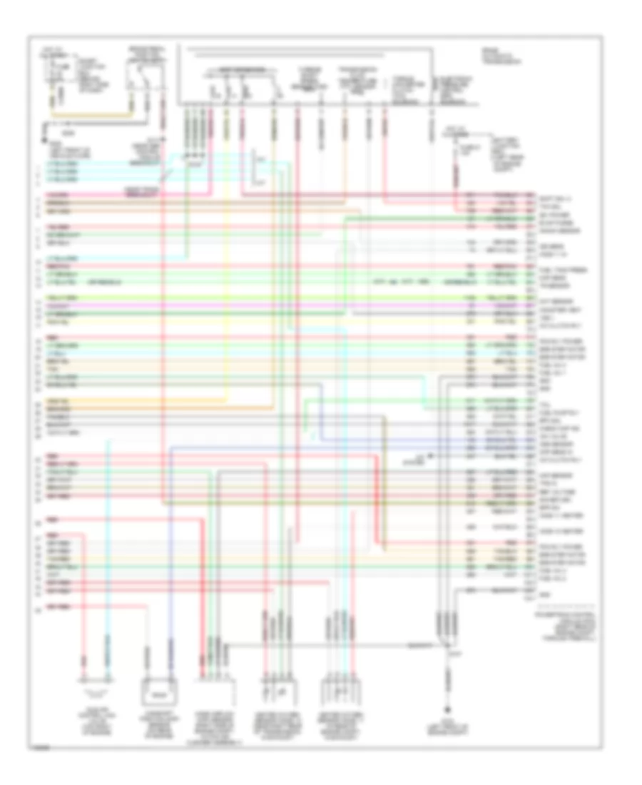
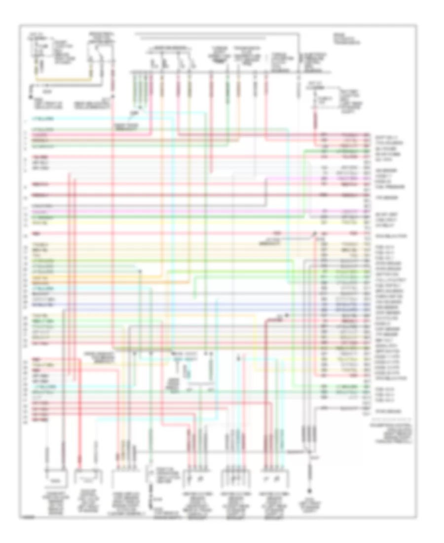
2.3L, Engine Performance Wiring Diagram (3 of 4) for Ford Ranger 2004
List of elements for 2.3L, Engine Performance Wiring Diagram (3 of 4) for Ford Ranger 2004:
- (at pcm break- out)
- (left side of dash) g204
- (left side of engine compt) g103
- (near smart junction box breakout)
- A/t
- C122
- C220a
- C220b
- C2280a
- C281b
- Check fuel cap ind
- Egr stepper motor (on rear of engine)
- Evap emissions canister vent valve (at fuel tank)
- Fail- safe cool ind
- Four-wheel drive control module
- Fuel injectors
- Fuel lev sig
- Fuel pump/ fuel gauge sensor
- Fuel tank pressure transducer sensor (at fuel tank assembly)
- Fuse 10a
- Hot in run
- Inertia fuel shut-off (ifs) switch (in right kick panel)
- Instrument cluster
- Low current board
- M/t
- Microprocessor
- Nca
- O/d off ind
- Red
- Red/pnk
- S116 (near g102 breakout)
- S125 (near p93 break- out)
- S126
- S149 (near inj 4 breakout)
- S150
- S153 (near swirl control solenoid valve breakout)
- S213 (near instrument cluster breakout)
- S237
- S405
- Smart junction box (behind right side of dash)
- Speed control servo (right rear of engine compt)
- Tach sig
- Tan
- Tan/red
- Transmission control switch (on steering column)
- Transmissions system
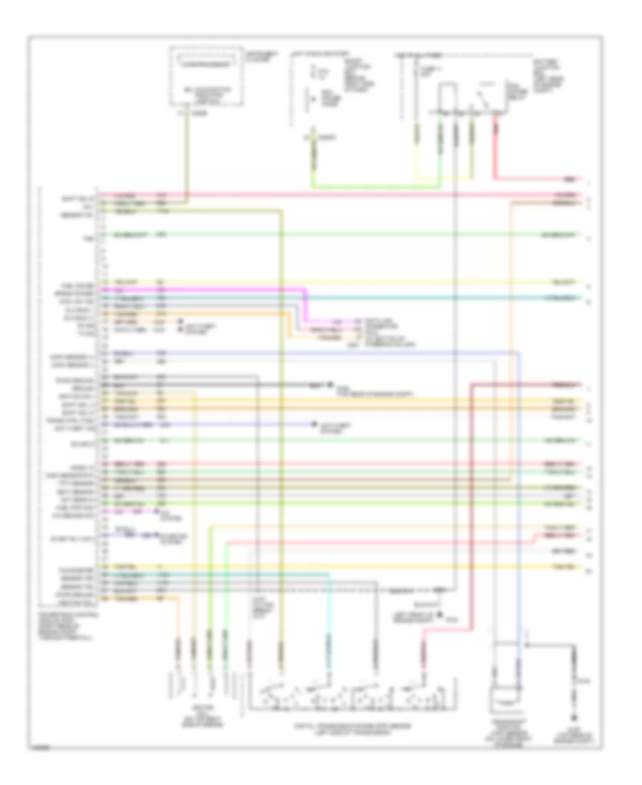
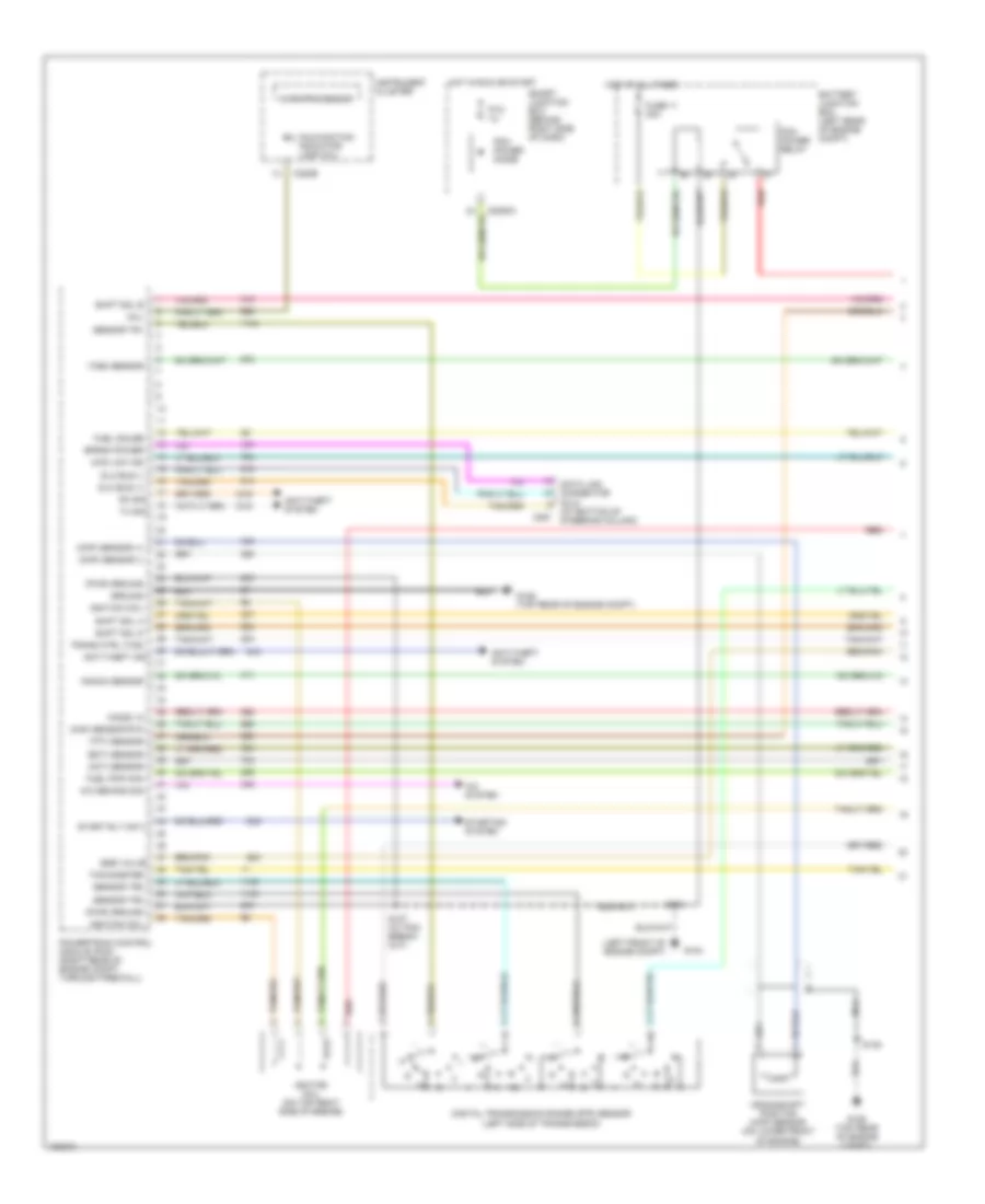
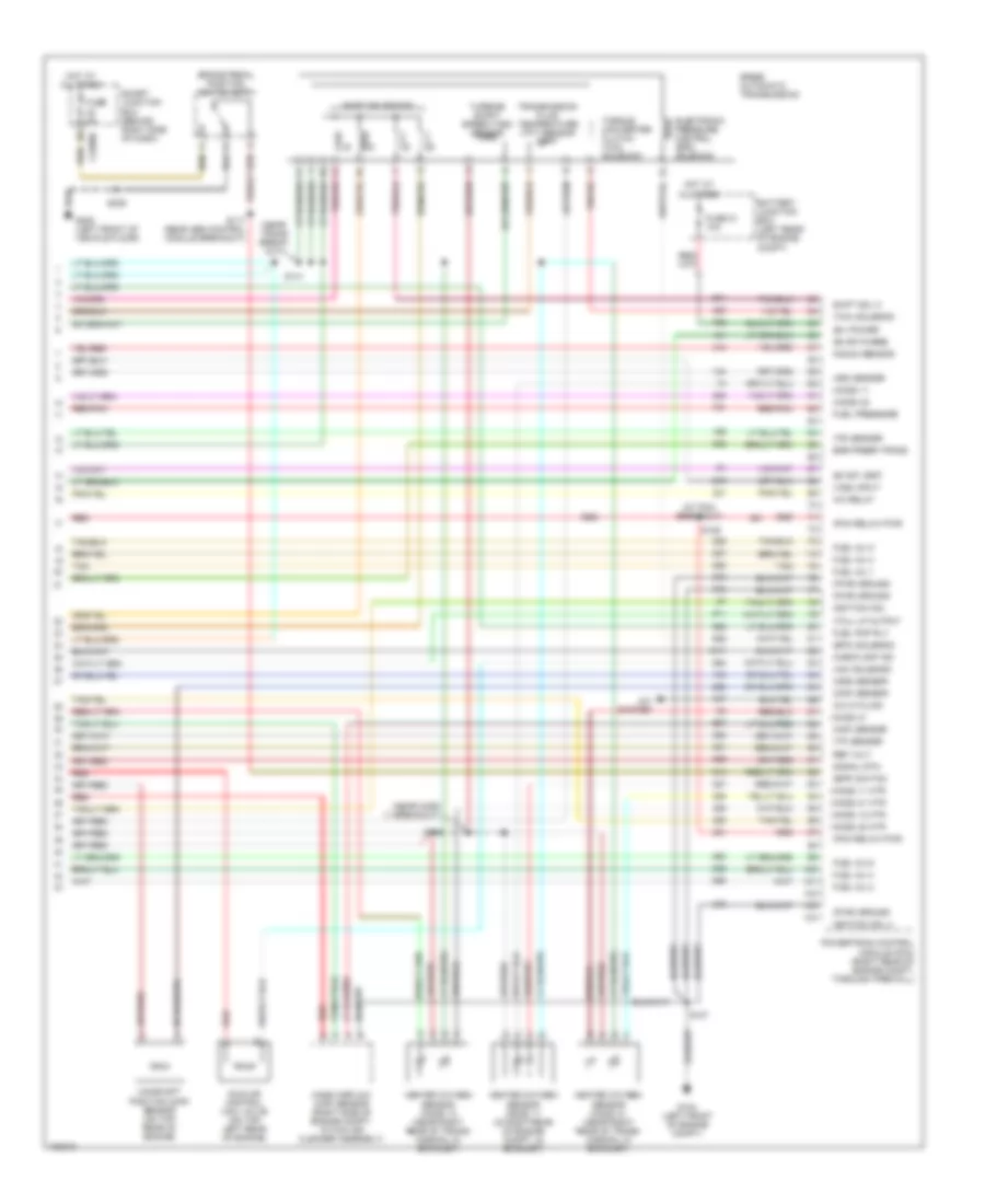
2.3L, Engine Performance Wiring Diagram (4 of 4) for Ford Ranger 2004
List of elements for 2.3L, Engine Performance Wiring Diagram (4 of 4) for Ford Ranger 2004:
- (a/t)
- (b+) power
- (m/t)
- (near trans breakout)
- 5r44e automatic transmission
- A/c clutch rly
- A/c system
- A/t
- Battery junction box (left rear of engine compt)
- Bpp sw
- Brake pedal position switch (bpp)
- C2280b
- Camshaft position (cmp) sensor (on rear of engine)
- Canister vent
- Check cap ind
- Cht sensor
- Cmp sens in
- Egr step motor
- Electronic pressure control (epc) solenoid
- Epc sol
- Evap purge
- Fuel inj 1
- Fuel inj 2
- Fuel inj 3
- Fuel inj 4
- Fuel pump rly
- Fuel tank press
- Fuse 21 10a
- Fuse 5a
- G104 (left front of engine compt)
- G205 (left front of vehicle floor)
- Gnd
- Heated oxygen sensor (ho2s) 11 (in rear of engine compt, in exhaust)
- Heated oxygen sensor (ho2s) 12 (near right rear of transmission, in exhaust)
- Ho2s 11 heater
- Ho2s 11 in
- Ho2s 12 heater
- Hot at all times
- Iac valve
- Idle air control (iac) valve (top right of engine)
- Iss sens
- Knock sensor
- M/t
- Maf sensor
- Map sens
- Mass airflow (maf) sensor (right side of engine compt, within air cleaner assembly)
- Oss sensor
- Pcm rly power
- Powertrain control module (pcm) (right rear of engine compt, through firewall)
- Red
- Red/pnk
- Ref voltage
- S107
- S117 (near abs control module breakout)
- S154
- S236
- Shift sol c
- Shift solenoids
- Sig return
- Smart junction box (behind right side of dash)
- Tan
- Tan/red
- Tcc sol
- Tcil
- Torque converter clutch (tcc) solenoid
- Tps in
- Tr sensor
- Transmission fluid temperature (tft) sensor
- Turbine shaft speed sensor (tss)
- Vss +
3.0L
3.0L, Engine Performance Wiring Diagram (1 of 4) for Ford Ranger 2004
List of elements for 3.0L, Engine Performance Wiring Diagram (1 of 4) for Ford Ranger 2004:
- (ckp) sensor (+)
- (ckp) sensor (-)
- (dlc) (at bottom of steering column) c251
- (ect) sensor
- (ho2s) 12
- (left front of engine compt)
- (maf) sensor rtn
- (mil)
- (pwr) ground
- (tft) sensor
- 4wd low ind
- A/c demand sig
- A/c system
- Act sens in
- Anti-theft ind
- Anti-theft system
- Battery junction box (left rear of engine compt)
- C220b
- Connector
- Crankshaft position (ckp) sensor (on lower front of engine)
- Data link
- Digital transmission range (dtr) sensor (left side of transmission)
- Dlc bus (+)
- Dlc bus (-)
- Eprom power
- Fuel gauge
- Fuel pmp mon
- Fuse 11 30a
- G104
- G106 (top rear of engine compt)
- Ground
- Hot at all times
- Hot in run or start
- Ignition coil
- Ignition coil (on top right side of engine)
- Instrument cluster
- Ks input
- Malfunction indicator lamp (mil)
- Microprocessor
- Nca
- Pcm power diode
- Pcm power relay
- Powertrain control module (pcm) (right rear of engine compt, through firewall)
- Ptc 1a
- Red
- Rx sig
- S107 (at pcm break- out)
- S118
- S145
- Sensor tr1
- Sensor tr2
- Sensor tr4
- Shift sol a
- Shift sol b
- Shift sol d
- Smart junction box (behind right side of dash)
- Start rly cntl
- Starting system
- Tachometer
- Trans ctrl (tcs)
- Tss
- Tx sig
3.0L, Engine Performance Wiring Diagram (2 of 4) for Ford Ranger 2004
List of elements for 3.0L, Engine Performance Wiring Diagram (2 of 4) for Ford Ranger 2004:
- (a/t)
- (at bat junction box breakout) s113
- (m/t)
- (near inj 6 breakout) s139
- (not used)
- A/c clutch relay
- A/t
- Air charge temperature (act) sensor (integral to mass airflow (maf) sensor)
- Battery junction box (left rear of engine compt)
- Clutch pedal position (cpp) switch (top of pedal support)
- Cooling fans system (engine cooling fan relay)
- Engine coolant temperature (ect) sensor (top front of engine)
- Evap canister purge valve (in left front of engine compt)
- Evap emissions canister vent valve (at fuel tank)
- Fuel pump relay
- Fuse 23 20a
- Fuse 41 15a
- Hot at all times
- Intermediate shaft speed (iss) sensor (left side of transmission)
- Knock sensor (on right side of engine)
- M/t
- Nca
- Output shaft speed (oss) sensor (left rear of transmission)
- Red
- S111 (at c144 breakout)
- S137 (near inj 5 breakout)
- S143 (at pcm breakout)
- Throttle position (tp) sensor (top left front of engine, on throttle body)
3.0L, Engine Performance Wiring Diagram (3 of 4) for Ford Ranger 2004
List of elements for 3.0L, Engine Performance Wiring Diagram (3 of 4) for Ford Ranger 2004:
- (left side of engine compt) g103
- (near smart junction box breakout)
- (under front of center console) g204
- 4wd low ind
- A/t
- C122
- C220a
- C220b
- C2280a
- C281b
- Check fuel cap ind
- Four wheel drive control module (behind left center of dash)
- Fuel injectors
- Fuel lev sig
- Fuel pump/ fuel gauge sensor
- Fuel tank pressure transducer sensor (at fuel tank assembly)
- Fuse 10a
- Heated oxygen sensor (ho2s) 22 (right rear of engine in exhaust)
- Hot in run
- Inertia fuel shut-off (ifs) switch (in right kick panel)
- Instrument cluster
- Low current board
- M/t
- Microprocessor
- Nca
- O/d off ind
- Red
- Red/pnk
- S101 red (near inj 3 breakout)
- S104 red (near ho2s 21 breakout)
- S116 (near g102 breakout)
- S125 (near p93 breakout)
- S126
- S213 (near instrument cluster breakout)
- S237
- S258
- S405
- Smart junction box (behind right side of dash)
- Speed control servo (right rear of engine compt)
- Tach sig
- Tan
- Transmission control switch (on steering column)
- Transmissions system
3.0L, Engine Performance Wiring Diagram (4 of 4) for Ford Ranger 2004
List of elements for 3.0L, Engine Performance Wiring Diagram (4 of 4) for Ford Ranger 2004:
- (at pcm breakout)
- (b+) power
- (bpp) switch
- (cmp) sensor
- (epc) solenoid
- (evap) purge
- (evap) vent
- (ho2s) 11
- (ho2s) 11 htr
- (ho2s) 12 htr
- (ho2s) 21
- (ho2s) 21 htr
- (ho2s) 22
- (ho2s) 22 htr
- (iac) solenoid
- (maf) sensor
- (near camshaft pos sensor breakout)
- (near trans break- out)
- (near trans breakout)
- (pcm relay) pwr
- (pwr) ground
- (tcc) solenoid
- (tcil) lp output
- (tp) sensor
- (tr) sensor
- (vss) input
- (w/a/t)
- (w/m/t)
- 5r44e automatic transmission
- A/c cycling
- A/c relay
- A/c system
- A/t
- Battery junction box (left rear of engine compt)
- Brake pedal position switch (bpp)
- C2280b
- Camshaft position (cmp) sensor (on top rear of engine)
- Check cap ind
- Electronic pressure control (epc) solenoid
- Fuel inj 1
- Fuel inj 2
- Fuel inj 3
- Fuel inj 4
- Fuel inj 5
- Fuel inj 6
- Fuel pmp rly
- Fuel pressure
- Fuse 21 10a
- Fuse 5a
- G104 (left front of engine compt)
- G106 (top rear of engine compt)
- G205 (left front of vehicle floor)
- Heated oxygen sensor (ho2s) 11 (in right rear of engine compt, in exhaust)
- Heated oxygen sensor (ho2s) 12 (near right rear of trans- mission, in exhaust)
- Heated oxygen sensor (ho2s) 21 (in left rear of engine compt, in exhaust)
- Hot at all times
- Idle air control (iac) valve (on top left front of engine)
- Ignition coil
- Iss sensor
- Ks 1 rtn
- M/t
- Mass airflow (maf) sensor (right side of engine compt, within air cleaner assembly)
- Oss sensor
- Positive crankcase ventilation heater
- Powertrain control module (pcm) (right rear of engine compt, through firewall)
- Red
- Red/pnk
- Ref volt
- S100
- S106
- S107
- S117 (near abs control module breakout)
- S129
- S141
- S145
- S236
- Shift sol c
- Shift solenoids
- Signal rtn
- Smart junction box (behind right side of dash)
- Tan
- Torque converter clutch (tcc) solenoid
- Transmission fluid temperature (tft) sensor
- Turbine shaft speed (tss) sensor
4.0L
4.0L, Engine Performance Wiring Diagram (1 of 4) for Ford Ranger 2004
List of elements for 4.0L, Engine Performance Wiring Diagram (1 of 4) for Ford Ranger 2004:
- (act) sensor
- (at bottom of steering column)
- (ckp) sensor (+)
- (ckp) sensor (-)
- (ect) sensor
- (ho2s) 12
- (left front of engine compt)
- (maf) sensor rtn
- (mil)
- (pwr) ground
- (tft) sensor
- (tss) sensor
- 4wd low ind
- A/c demand sig
- A/c system
- Anti-theft ind
- Anti-theft system
- Battery junction box (left rear of engine compt)
- C220b
- C251
- Crankshaft position (ckp) sensor (on lower front of engine)
- Data link connector (dlc)
- Digital transmission range (dtr) sensor (left side of transmission)
- Dlc bus (+)
- Dlc bus (-)
- Egr valve
- Eprom power
- Fuel gauge
- Fuel pmp mon
- Fuse 11 30a
- G104
- G106 (top rear of engine compt)
- Ground
- Hot at all times
- Hot in run or start
- Ignition coil
- Ignition coil (on top right side of engine)
- Instrument cluster
- Knock sensor
- Malfunction indicator lamp (mil)
- Microprocessor
- Nca
- Pcm power diode
- Pcm power relay
- Powertrain control module (pcm) (right rear of engine compt, through firewall)
- Ptc 1a
- Red
- Rx sig
- S107 (at pcm break- out)
- S118
- S145
- Sensor tr1
- Sensor tr2
- Sensor tr4
- Shift sol a
- Shift sol b
- Shift sol d
- Smart junction box (behind right side of dash)
- Start rly cntl
- Starting system
- Tachometer
- Trans ctrl (tcs)
- Tx sig
4.0L, Engine Performance Wiring Diagram (2 of 4) for Ford Ranger 2004
List of elements for 4.0L, Engine Performance Wiring Diagram (2 of 4) for Ford Ranger 2004:
- (a/t)
- (at battery junction box breakout) s113
- (at c144 breakout)
- (at pcm break- out)
- (m/t)
- (near inj 4 breakout)
- (near trans breakout) s137
- (not used)
- A/c clutch relay
- A/t
- Air charge temperature (act) sensor (integral to mass airflow (maf) sensor)
- Battery junction box (left rear of engine compt)
- Clutch pedal position (cpp) switch (top of pedal support)
- Cooling fans system (engine cooling fan relay)
- Egr pressure transducer (at top left of engine)
- Egr valve actuator (at top left of engine)
- Engine coolant temperature (ect) sensor (top front of engine)
- Evap canister purge valve (in left front of engine compt)
- Fuel pump relay
- Fuse 23 20a
- Fuse 41 15a
- Hot at all times
- Intermediate shaft speed (iss) sensor (above dtr sensor)
- Knock sensor (on top center of engine)
- M/t
- Nca
- Output shaft speed (oss) sensor (on left rear of trans)
- Red
- S111
- S133 (near ect sensor breakout)
- S135
- S143
- S144 (near ho2s 12 breakout)
- S146 (near trans breakout)
- Throttle position (tp) sensor (top left front of engine, on throttle body)
4.0L, Engine Performance Wiring Diagram (3 of 4) for Ford Ranger 2004
List of elements for 4.0L, Engine Performance Wiring Diagram (3 of 4) for Ford Ranger 2004:
- (left side of engine compt) g103
- (near ignition coil breakout) s104 red
- (near inj 3 breakout) s101
- (near smart junction box breakout)
- (under front of center console) g204
- 4wd low ind
- C122
- C220a
- C220b
- C2280a
- C281b
- Check fuel cap ind
- Evap emissions canister vent valve (at fuel tank)
- Four wheel drive control module (in right kick panel)
- Fuel injectors
- Fuel lev sig
- Fuel pump/ fuel gauge sensor
- Fuel tank pressure transducer sensor (at fuel tank assembly)
- Fuse 10a
- Heated oxygen sensor (ho2s) 22 (right rear of engine in exhaust)
- Hot in run
- Ignition transform capacitor
- Inertia fuel shut-off (ifs) switch (in right kick panel)
- Instrument cluster
- Low current board
- Microprocessor
- Nca
- O/d off ind
- Red
- Red/pnk
- S116 (near g102 breakout)
- S125 (near p93 breakout)
- S126
- S213 (near instrument cluster breakout)
- S237
- S258 (near smart junction box breakout)
- S405
- Smart junction box (behind right side of dash)
- Speed control servo (right rear of engine compt)
- Tach sig
- Tan
- Transmission control switch (on steering column)
- Transmissions system
4.0L, Engine Performance Wiring Diagram (4 of 4) for Ford Ranger 2004
List of elements for 4.0L, Engine Performance Wiring Diagram (4 of 4) for Ford Ranger 2004:
- (at pcm breakout)
- (b+) power
- (bpp) switch
- (cmp) sensor
- (epc) solenoid
- (evap) purge
- (evap) vent
- (ho2s) 11
- (ho2s) 11 htr
- (ho2s) 12 htr
- (ho2s) 21
- (ho2s) 21 htr
- (ho2s) 22
- (ho2s) 22 htr
- (iac) solenoid
- (iss) sensor
- (maf) sensor
- (near hos2 11 breakout)
- (near trans break- out)
- (oss) sensor
- (pcm relay) pwr
- (pwr) ground
- (tcc) solenoid
- (tcil) lp output
- (tp) sensor
- (tr) sensor
- (vss) input
- 5r55e automatic transmission
- A/c cycling
- A/c relay
- A/c system
- Battery junction box (left rear of engine compt)
- Brake pedal position switch (bpp)
- C2280b
- Camshaft position (cmp) sensor (on top rear of engine)
- Check cap ind
- Egr prssr trans
- Electronic pressure control (epc) solenoid
- Fuel inj 1
- Fuel inj 2
- Fuel inj 3
- Fuel inj 4
- Fuel inj 5
- Fuel inj 6
- Fuel pmp rly
- Fuel pressure
- Fuse 21 10a
- Fuse 5a
- G104 (left front of engine compt)
- G205 (left front of vehicle floor)
- Heated oxygen sensor (ho2s) 11 (in right rear of engine compt, in exhaust)
- Heated oxygen sensor (ho2s) 12 (near right rear of trans- mission, in exhaust)
- Heated oxygen sensor (ho2s) 21 (near right rear of trans- mission, in exhaust)
- Hot at all times
- Idle air control (iac) valve (on top left rear of engine)
- Ignition coil
- Ignition coil 4
- Knock sensor
- Mass airflow (maf) sensor (right side of engine compt, within air cleaner assembly)
- Powertrain control module (pcm) (right rear of engine compt, through firewall)
- Red
- Red/pnk
- Ref volt
- S107
- S117 (near abs control module breakout)
- S129
- S140
- S141
- S236
- Shift sol c
- Shift solenoids
- Signal rtn
- Smart junction box (behind right side of dash)
- Tan
- Torque converter clutch (tcc) solenoid
- Transmission fluid temperature (tft) sensor
- Turbine shaft speed (tss) sensor