ENGINE PERFORMANCE
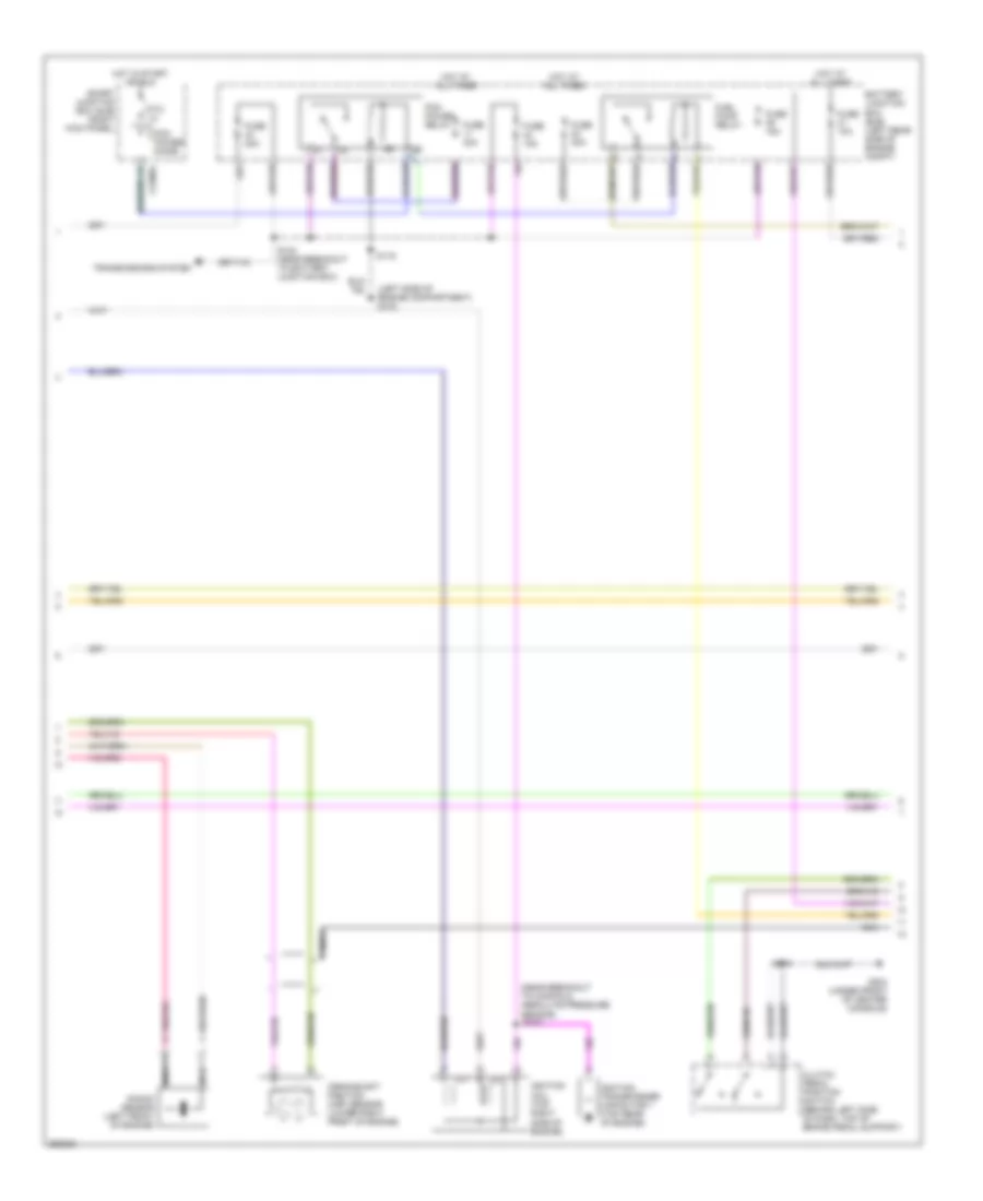
2.3L
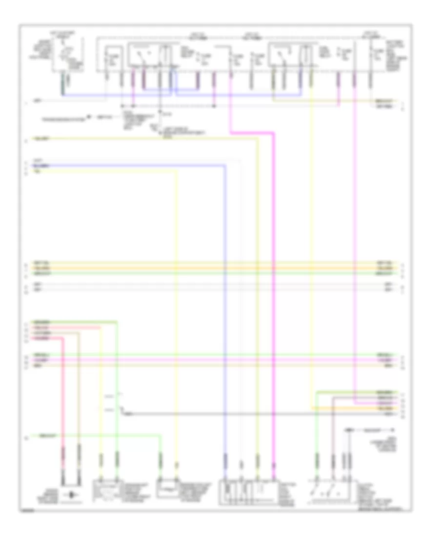
2.3L, Engine Performance Wiring Diagram (1 of 4) for Ford Ranger 2007

List of elements for 2.3L, Engine Performance Wiring Diagram (1 of 4) for Ford Ranger 2007:
- (in engine control sensor & fuel charge harness, near breakout to g106) s101
- (near breakout to heated oxygen sensor 11)
- (right rear of engine compartment)
- C175e
- Camshaft position sensor (rear of engine)
- Cd1
- Cd2
- Ce101
- Ce102
- Ce103
- Ce104
- Ce116
- Ce124
- Ce125
- Ce132
- Ce205
- Ce206
- Ce207
- Ce208
- Ce235
- Ce301
- Cht
- Ckpn
- Ckpp
- Cmp1
- Cooling fans system
- Cylinder head temperature (cht) sensor (right side of cylinder head)
- Dpfe
- Egr stepper motor (rear of engine)
- Evap canister purge valve (left side of engine compartment)
- Evmv
- Evr
- Fci
- G107
- Heated oxygen sensor (ho2s) 11 (rear of engine compartment, in exhaust)
- Ho2s 11
- Htr-11
- Iac
- Iat
- Idle air control (iac) valve (top right of engine)
- Inj 1
- Inj 2
- Inj 3
- Inj 4
- Ks1n
- Ks1p
- Le423
- Maf
- Mafrtn
- Manifold absolute pressure (map) sensor (top of engine)
- Map
- Mass air flow/intake air temperature (maf/iat) sensor (right side of engine compartment, in air cleaner assembly)
- Nca
- Powertrain control module (pcm) (right rear of engine compartment)
- Re135
- Re320
- Re323
- Re405
- S100
- S103 (in engine control sensor & fuel charge harness, near breakout to manifold absolute pressure sensor)
- S108
- S118 (near breakout to battery junction box)
- Sigrtn
- Throttle position (tps) sensor (top right side of engine, on throttle body)
- Tps
- Ve706
- Ve711
- Ve735
- Ve740
- Ve801
- Ve803
- Ve807
- Ve819
- Vh101
- Vref
- Vrefe
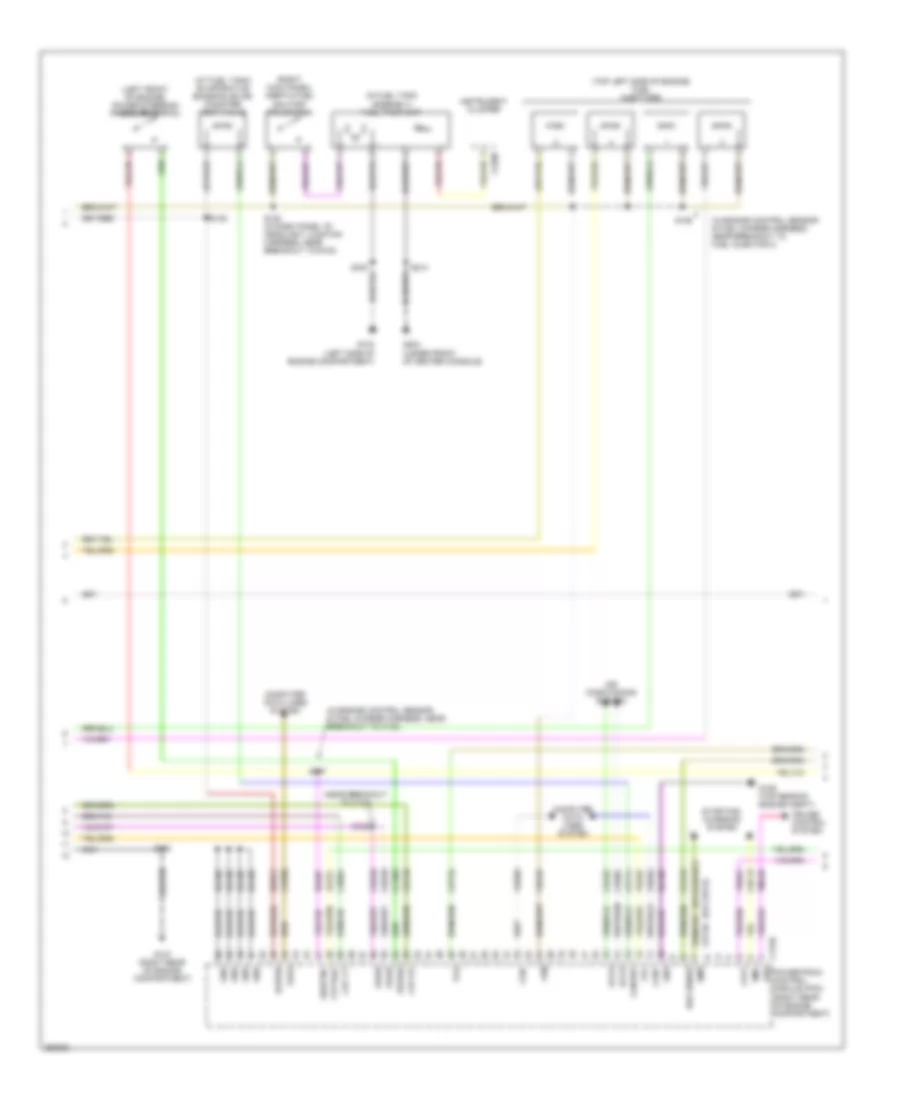
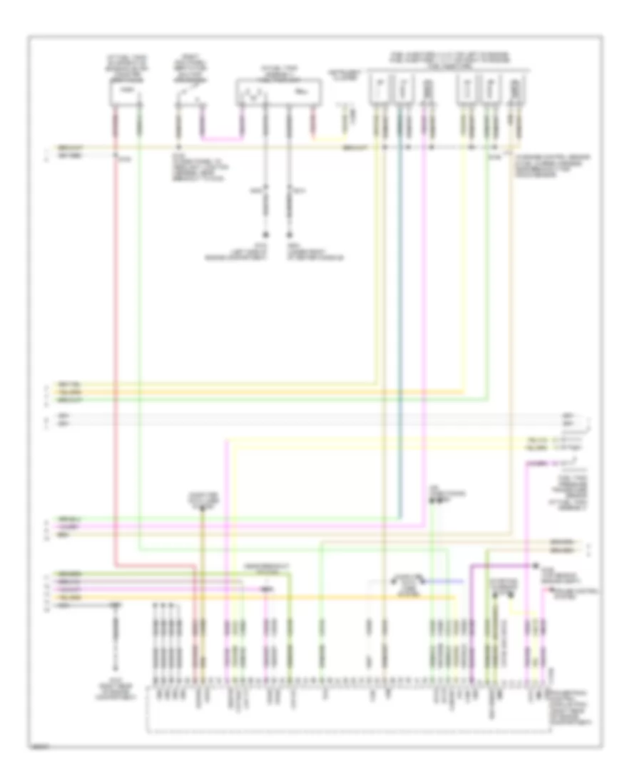
2.3L, Engine Performance Wiring Diagram (2 of 4) for Ford Ranger 2007
List of elements for 2.3L, Engine Performance Wiring Diagram (2 of 4) for Ford Ranger 2007:
- (left side of engine compartment) g103
- (near breakout to manifold absolute pressure sensor)
- Battery junction box (bjb) (left rear side of engine compt)
- C2280a
- Clutch pedal position switch (behind left side of dash, top of brake pedal support)
- Crankshaft position (ckp) sensor (lower right front of engine)
- Fuel pump relay
- Fuse 10a
- Fuse 15a
- Fuse 20a
- Fuse 30a
- G204 (under front of center console)
- Hot at all times
- Hot in start or run
- Ignition coil (top right side of engine)
- Ignition transformer capacitor 1 (top rear of engine)
- Knock sensor (left front of engine)
- Nca
- Pcm power diode
- Pcm power relay
- Ptc 1a
- S104
- S116
- S123 (near breakout to battery junction box)
- S214
- Smart junction box (sjb) (right kick panel)
- Transmissions system
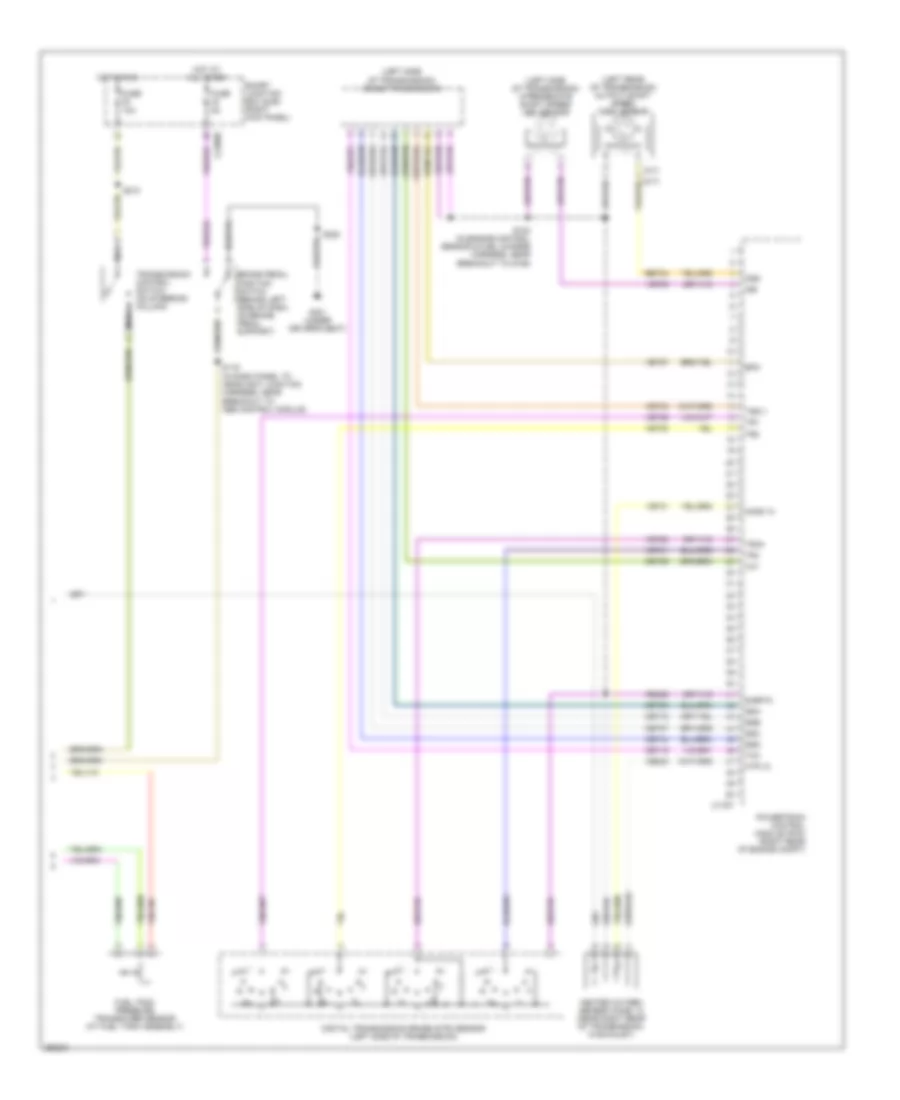
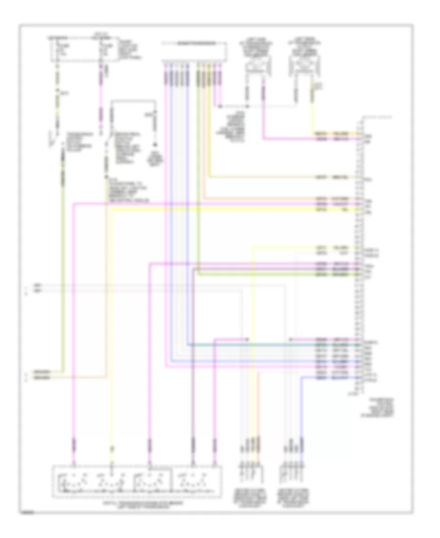
2.3L, Engine Performance Wiring Diagram (3 of 4) for Ford Ranger 2007
List of elements for 2.3L, Engine Performance Wiring Diagram (3 of 4) for Ford Ranger 2007:
- (at fuel tank) evaporative emission (evap) canister vent valve
- (in engine control sensor & fuel charge harness, near breakout to c133)
- (in engine control sensor & fuel charge harness, near breakout to fuel injector 3)
- (in fuel tank assembly) fuel tank unit
- (left front of engine) power steering pressure switch
- (near breakout to c133)
- (or cbp21)
- (right kick panel) inertia fuel shutoff (ifs) switch
- (top left side of engine) fuel injectors
- Accr
- Accs
- Air conditioning system
- Boo sense
- C175b
- C220b
- Can+
- Can-
- Canvnt
- Cbb39
- Ccb15
- Ccs09
- Cdb08
- Cdc12
- Cdc36
- Ce114
- Ce904
- Cet34
- Cet40
- Ch302
- Ch425
- Computer data lines system
- Cpp bt
- Cpp tt
- Cruise control system
- Feps
- Fpc
- Fpm
- Ftpt
- Ftptref
- G103 (left side of engine compartment)
- G106 (top rear of engine compt)
- G107 (right rear of engine compartment)
- G204 (under front of center console)
- Gd108
- Gnd
- Instrument cluster
- Kapwr
- Le424
- Nca
- Powertrain control module (pcm) (right rear of engine compartment)
- Pspsw
- Re407
- S100
- S105
- S106
- S107
- S109
- S120 (in dash panel to headlight junction harness, near breakout to g102)
- S214
- Sbb21
- Sigrtnc
- Smc
- Smr
- Starting/ charging system
- Tcs
- Vdb04
- Vdb05
- Ve225
- Ve518
- Ve922
- Vmc05
- Vpwr
- Vss
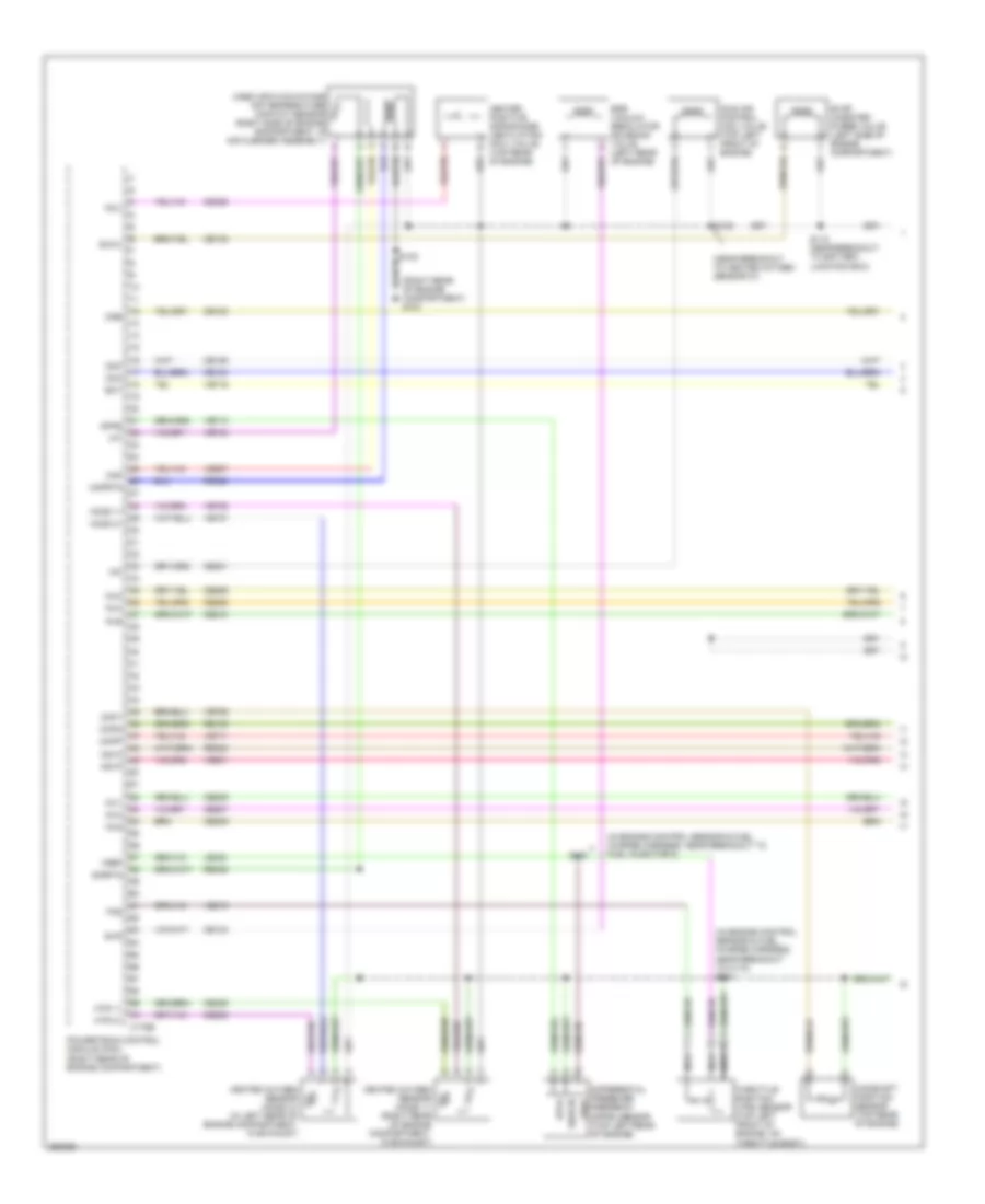
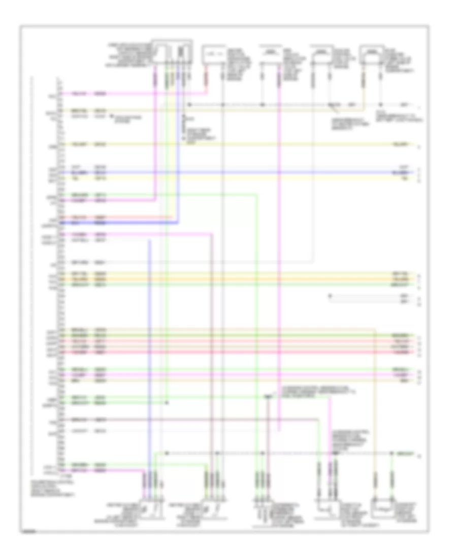
2.3L, Engine Performance Wiring Diagram (4 of 4) for Ford Ranger 2007
List of elements for 2.3L, Engine Performance Wiring Diagram (4 of 4) for Ford Ranger 2007:
- (a/t)
- (left rear of transmission) output shaft speed (oss) sensor
- (left side of transmission) 5r44e transmission
- (left side of transmission) intermediate shaft speed (iss) sensor
- (m/t)
- Brake pedal position switch (behind left side of dash, on brake pedal support)
- C175t
- C2280b
- Ce233
- Cet05
- Cet06
- Cet07
- Cet18
- Cet19
- Cet44
- Digital transmission range (dtr) sensor (left side of transmission)
- Epc
- Fuel tank pressure transducer sensor (at fuel tank assembly)
- Fuse 10a
- Fuse 5a
- G301 (under driver's seat)
- Heated oxygen sensor (ho2s) 12 (near right rear of transmission, in exhaust)
- Ho2s 12
- Hot at all times
- Hot in run
- Htr 12
- Iss
- Nca
- Oss
- Powertrain control module (pcm) (right rear of engine compt)
- Re406
- Ret04
- S102 (in engine control sensor & fuel charge harness, near breakout to g106)
- S119 (in dash panel to headlight junction harness, near breakout to abs control module)
- S210
- S220
- Sigrtn
- Smart junction box (sjb) (right kick panel)
- Ssa
- Ssb
- Ssc
- Ssd
- Tcc
- Tft
- Tr1
- Tr2
- Tr3a
- Tr4
- Transmission control switch (on steering column)
- Tss v
- Ve731
- Ve739
- Vet27
- Vet28
- Vet29
- Vet30
- Vet31
- Vet33
3.0L
3.0L, Engine Performance Wiring Diagram (1 of 4) for Ford Ranger 2007
List of elements for 3.0L, Engine Performance Wiring Diagram (1 of 4) for Ford Ranger 2007:
- (in engine control sensor & fuel charge harness, near breakout to c110) s101
- (in engine control sensor & fuel charge harness, near breakout to fuel injector 5)
- (near breakout to heated oxygen sensor 21)
- (right rear of engine compartment) g107
- C175e
- Camshaft position sensor (top rear of engine)
- Cda
- Cdb
- Cdc
- Ce123
- Ce124
- Ce125
- Ce132
- Ce133
- Ce205
- Ce206
- Ce207
- Ce208
- Ce209
- Ce210
- Ce235
- Ce236
- Ce301
- Ce328
- Ckpn
- Ckpp
- Cmp1
- Differential pressure feedback (dpfe) sensor (top left rear of engine)
- Dpfe
- Ect
- Egr vacuum regulator solenoid valve (left rear of engine)
- Evap canister purge valve (left side of engine compartment)
- Evmv
- Evr
- Heated oxygen sensor (ho2s) 11 (right rear of engine compartment, in exhaust)
- Heated oxygen sensor (ho2s) 21 (in left rear of engine compartment, in exhaust)
- Heated positive crankcase ventilation (pcv) valve (top rear of engine)
- Ho2s 11
- Ho2s 21
- Htr 11
- Htr 21
- Iac
- Iat
- Idle air control (iac) valve (top left front of engine)
- Inj1
- Inj2
- Inj3
- Inj4
- Inj5
- Inj6
- Ks1n
- Ks1p
- Le423
- Maf
- Mafrtn
- Mass air flow/intake air temperature (maf/iat) sensor (right side of engine compartment, in air cleaner assembly)
- Nca
- Pcv
- Powertrain control module (pcm) (right rear of engine compartment)
- Re135
- Re320
- Re323
- Re405
- S103
- S108
- S118 (near breakout to battery junction box)
- Sigrtn
- Throttle position (tps) sensor (top left front of engine, on throttle body)
- Tps
- Ve706
- Ve711
- Ve713
- Ve716
- Ve735
- Ve737
- Ve740
- Ve801
- Ve807
- Ve819
- Vref
3.0L, Engine Performance Wiring Diagram (2 of 4) for Ford Ranger 2007
List of elements for 3.0L, Engine Performance Wiring Diagram (2 of 4) for Ford Ranger 2007:
- (left side of engine compartment) g103
- Battery junction box (bjb) (left rear side of engine compt)
- C2280a
- Clutch pedal position switch (behind left side of dash, top of brake pedal support)
- Crankshaft position sensor (lower front of engine)
- Engine coolant temperature (ect) sensor (top front of engine)
- Fuel pump relay
- Fuse 10a
- Fuse 15a
- Fuse 20a
- Fuse 30a
- G204 (under front of center console)
- Hot at all times
- Hot in start or run
- Ignition coil (top right side of engine)
- Knock sensor (right side of engine)
- Nca
- Pcm power diode
- Pcm power relay
- Ptc 1a
- S116
- S123 (near breakout to battery junction box)
- S214
- Smart junction box (sjb) (right kick panel)
- Transmissions system
3.0L, Engine Performance Wiring Diagram (3 of 4) for Ford Ranger 2007
List of elements for 3.0L, Engine Performance Wiring Diagram (3 of 4) for Ford Ranger 2007:
- (at fuel tank) evaporative emission (evap) canister vent valve
- (fuel injectors 4, 5, 6: top left of engine) (fuel injectors 1, 2, 3: top right of engine) fuel injectors
- (in engine control sensor & fuel charge harness, near breakout for knock sensor)
- (in fuel tank assembly) fuel tank unit
- (near breakout to c133)
- (or cbp21)
- (right kick panel) inertia fuel shutoff (ifs) switch
- Accr
- Accs
- Air conditioning system
- Boo sense
- C175b
- C220b
- Can+
- Can-
- Canvnt
- Cbb39
- Ccb15
- Cdb08
- Cdc12
- Cdc36
- Ce114
- Ce904
- Cet34
- Cet40
- Ch302
- Ch425
- Computer data lines system
- Cpp bt
- Cpp tt
- Cruise control system
- Feps
- Fpc
- Fpm
- Ftpt
- Ftptref
- Fuel tank pressure transducer sensor (at fuel tank assembly)
- G103 (left side of engine compartment)
- G106 (top rear of engine compt)
- G107 (right rear of engine compartment)
- G204 (under front of center console)
- Gd108
- Gnd
- Instrument cluster
- Kapwr
- Le424
- Nca
- Powertrain control module (pcm) (right rear of engine compartment)
- Re407
- S100
- S105
- S106
- S109
- S120 (in dash panel to headlight junction harness, near breakout to g102)
- S214
- Sbb21
- Sigrtn
- Smc
- Smr
- Starting/ charging system
- Tcs
- Vdb04
- Vdb05
- Ve225
- Ve518
- Ve922
- Vmc05
- Vpwr
- Vss
3.0L, Engine Performance Wiring Diagram (4 of 4) for Ford Ranger 2007
List of elements for 3.0L, Engine Performance Wiring Diagram (4 of 4) for Ford Ranger 2007:
- (left rear of transmission) output shaft speed (oss) sensor
- (left side of transmission) intermediate shaft speed (iss) sensor
- 5r44e transmission
- Brake pedal position switch (behind left side of dash, on brake pedal support)
- C175t
- C2280b
- Ce233
- Ce234
- Cet05
- Cet06
- Cet07
- Cet18
- Cet19
- Cet44
- Digital transmission range (dtr) sensor (left side of transmission)
- Fuse 10a
- Fuse 5a
- G301 (under driver's seat)
- Heated oxygen sensor (ho2s) 12 (near right rear of transmission, in exhaust)
- Heated oxygen sensor (ho2s) 22 (near left side of transmission, in exhaust)
- Ho2s 12
- Ho2s 22
- Hot at all times
- Hot in run
- Htr 12
- Htr 22
- Iss
- Nca
- Oss
- Pca
- Powertrain control module (pcm) (right rear of engine compt)
- Re406
- Ret04
- S102 (in engine control sensor & fuel charge harness, near breakout to c110)
- S119 (in dash panel to headlight junction harness, near breakout to abs control module)
- S210
- Sigrtn
- Smart junction box (sjb) (right kick panel)
- Ssa
- Ssb
- Ssc
- Ssd
- Tcc
- Tft
- Tr1
- Tr2
- Tr3a
- Tr4
- Transmission control switch (on steering column)
- Tss
- Ve731
- Ve733
- Ve739
- Vet27
- Vet28
- Vet29
- Vet30
- Vet31
- Vet33
4.0L
4.0L, Engine Performance Wiring Diagram (1 of 4) for Ford Ranger 2007
List of elements for 4.0L, Engine Performance Wiring Diagram (1 of 4) for Ford Ranger 2007:
- (in engine control sensor & fuel charge harness, near breakout to fuel injector 5)
- (in engine control sensor & fuel charge harness, near breakout to g106) s101
- (near breakout to heated oxygen sensor 21)
- (right rear of engine compartment) g107
- C175e
- Camshaft position sensor (top left of engine)
- Cda
- Cdb
- Cdc
- Ce123
- Ce124
- Ce125
- Ce132
- Ce133
- Ce205
- Ce206
- Ce207
- Ce208
- Ce209
- Ce210
- Ce235
- Ce236
- Ce301
- Ce328
- Ckpn
- Ckpp
- Cmp1
- Cooling fans system
- Differential pressure feedback (dpfe) sensor (top left rear of engine)
- Dpfe
- Ect
- Egr vacuum regulator solenoid valve (top left side of engine)
- Evap canister purge valve (left side of engine compartment)
- Evmv
- Evr
- Fci
- Heated oxygen sensor (ho2s) 11 (right rear of engine in exhaust)
- Heated oxygen sensor (ho2s) 21 (in left rear of engine compartment, in exhaust)
- Heated positive crankcase ventilation (pcv) valve (top left rear of engine)
- Ho2s 11
- Ho2s 21
- Htr 11
- Htr 21
- Iac
- Iat
- Idle air control (iac) valve (top of engine)
- Inj1
- Inj2
- Inj3
- Inj4
- Inj5
- Inj6
- Ks1n
- Ks1p
- Le423
- Maf
- Mafrtn
- Mass air flow/intake air temperature (maf/iat) sensor (right side of engine compartment, in air cleaner assembly)
- Nca
- Pcv
- Powertrain control module (pcm) (right rear of engine compartment)
- Re135
- Re320
- Re323
- Re405
- S103
- S108
- S118 (near breakout to battery junction box)
- Sigrtn
- Throttle position (tps) sensor (top front of engine, on throttle body)
- Tps
- Ve706
- Ve711
- Ve713
- Ve716
- Ve735
- Ve737
- Ve740
- Ve801
- Ve807
- Ve819
- Vh101
- Vref
4.0L, Engine Performance Wiring Diagram (2 of 4) for Ford Ranger 2007
List of elements for 4.0L, Engine Performance Wiring Diagram (2 of 4) for Ford Ranger 2007:
- (left side of engine compartment) g103
- (near breakout to battery junction box)
- (near breakout to fuel injector 6) s104
- Battery junction box (bjb) (left rear side of engine compt)
- C2280a
- Clutch pedal position switch (behind left side of dash, top of brake pedal support)
- Crankshaft position sensor (lower front of engine)
- Engine coolant temperature (ect) sensor (top right front of engine)
- Fuel pump relay
- Fuse 10a
- Fuse 15a
- Fuse 20a
- Fuse 30a
- G204 (under front of center console)
- Hot at all times
- Hot in start or run
- Ignition coil (top left rear of engine)
- Ignition transformer capacitor 1 (top left side of engine)
- Knock sensor (top center of engine)
- Nca
- Pcm power diode
- Pcm power relay
- Ptc 1a
- S116
- S123
- S214
- Smart junction box (sjb) (right kick panel)
- Transmissions system
4.0L, Engine Performance Wiring Diagram (3 of 4) for Ford Ranger 2007
List of elements for 4.0L, Engine Performance Wiring Diagram (3 of 4) for Ford Ranger 2007:
- (at fuel tank) evaporative emission (evap) canister vent valve
- (fuel injectors 4, 5, 6: top left of engine) (fuel injectors 1, 2, 3: top right of engine) fuel injectors
- (in engine control sensor & fuel charge harness, near breakout to heated oxygen sensor 11)
- (in fuel tank assembly) fuel tank unit
- (near breakout to fuel injector 6)
- (or cbp21)
- (right kick panel) inertia fuel shutoff (ifs) switch
- Accr
- Accs
- Air conditioning system
- Boo sense
- C175b
- C220b
- Can+
- Can-
- Canvnt
- Cbb39
- Ccb15
- Cdb08
- Cdc12
- Cdc36
- Ce114
- Ce904
- Cet34
- Cet40
- Ch302
- Ch425
- Computer data lines system
- Cpp bt
- Cpp tt
- Cruise control system
- Feps
- Fpc
- Fpm
- Ftpt
- Ftptref
- Fuel tank pressure transducer sensor (at fuel tank assembly)
- G103 (left side of engine compartment)
- G106 (top rear of engine compt)
- G107 (right rear of engine compartment)
- G204 (under front of center console)
- Gd108
- Gnd
- Instrument cluster
- Kapwr
- Le424
- Nca
- Powertrain control module (pcm) (right rear of engine compartment)
- Re407
- S100
- S105
- S106
- S109
- S120 (in dash panel to headlight junction harness, near breakout to g102)
- S214
- Sbb21
- Sigrtn
- Smc
- Smr
- Starting/ charging system
- Tcs
- Vdb04
- Vdb05
- Ve225
- Ve518
- Ve922
- Vmc05
- Vpwr
- Vs out
4.0L, Engine Performance Wiring Diagram (4 of 4) for Ford Ranger 2007
List of elements for 4.0L, Engine Performance Wiring Diagram (4 of 4) for Ford Ranger 2007:
- (left rear of transmission) output shaft speed (oss) sensor
- (left side of transmission) 5r55e transmission
- (left side of transmission) intermediate shaft speed (iss) sensor
- Brake pedal position switch (behind left side of dash, on brake pedal support)
- C175t
- C2280b
- Ce233
- Ce234
- Cet05
- Cet06
- Cet07
- Cet18
- Cet19
- Cet44
- Digital transmission range (dtr) sensor (left side of transmission)
- Fuse 10a
- Fuse 5a
- G301 (under driver's seat)
- Heated oxygen sensor (ho2s) 12 (near right rear of transmission, in exhaust)
- Heated oxygen sensor (ho2s) 22 (near left side of transmission, in exhaust)
- Ho2s 12
- Ho2s 22
- Hot at all times
- Hot in run
- Htr 12
- Htr 22
- Iss
- Nca
- Oss
- Pca
- Powertrain control module (pcm) (right rear of engine compt)
- Re406
- Ret04
- S102 (in engine control sensor & fuel charge harness, near breakout to g106)
- S119 (in dash panel to headlight junction harness, near breakout to abs control module)
- S210
- Sigrtn
- Smart junction box (sjb) (right kick panel)
- Ssa
- Ssb
- Ssc
- Ssd
- Tcc
- Tft
- Tr1
- Tr2
- Tr3a
- Tr4
- Transmission control switch (on steering column)
- Tss
- Ve731
- Ve733
- Ve739
- Vet27
- Vet28
- Vet29
- Vet30
- Vet31
- Vet33