ENGINE PERFORMANCE
5.4L
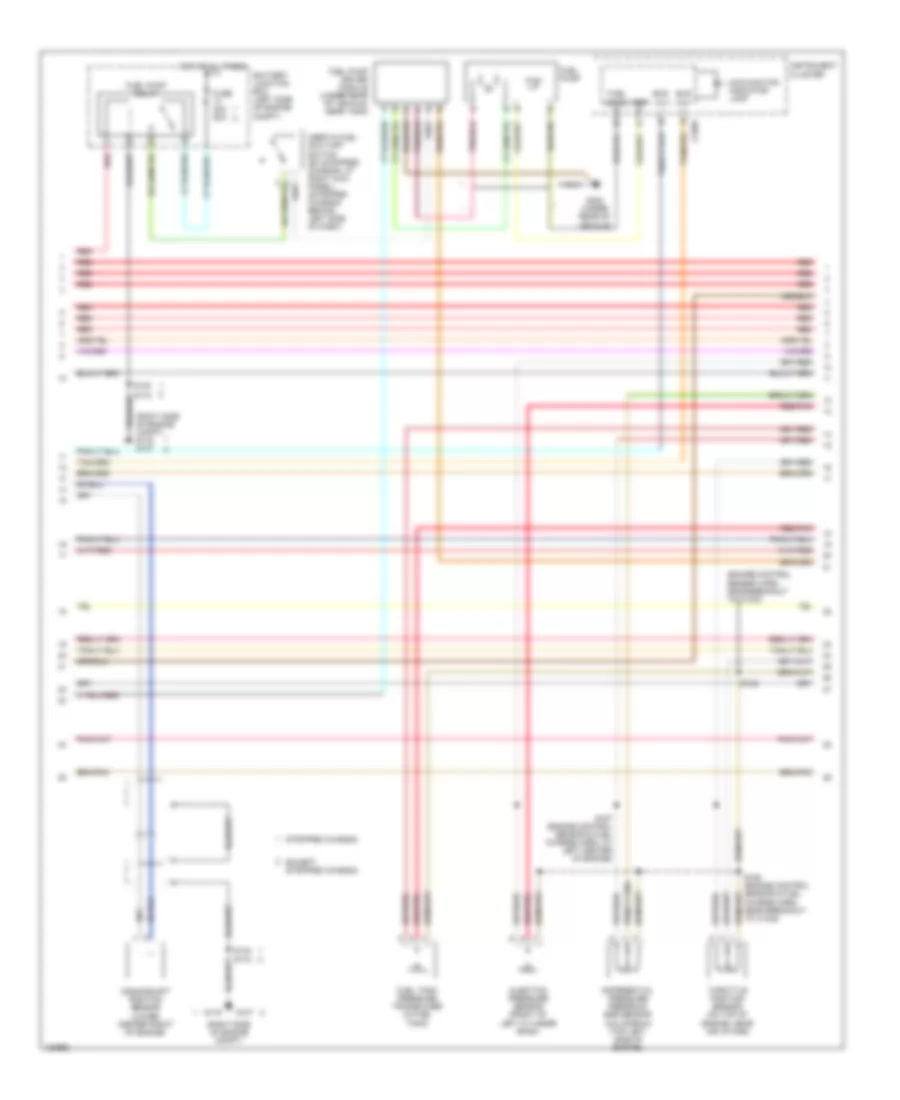
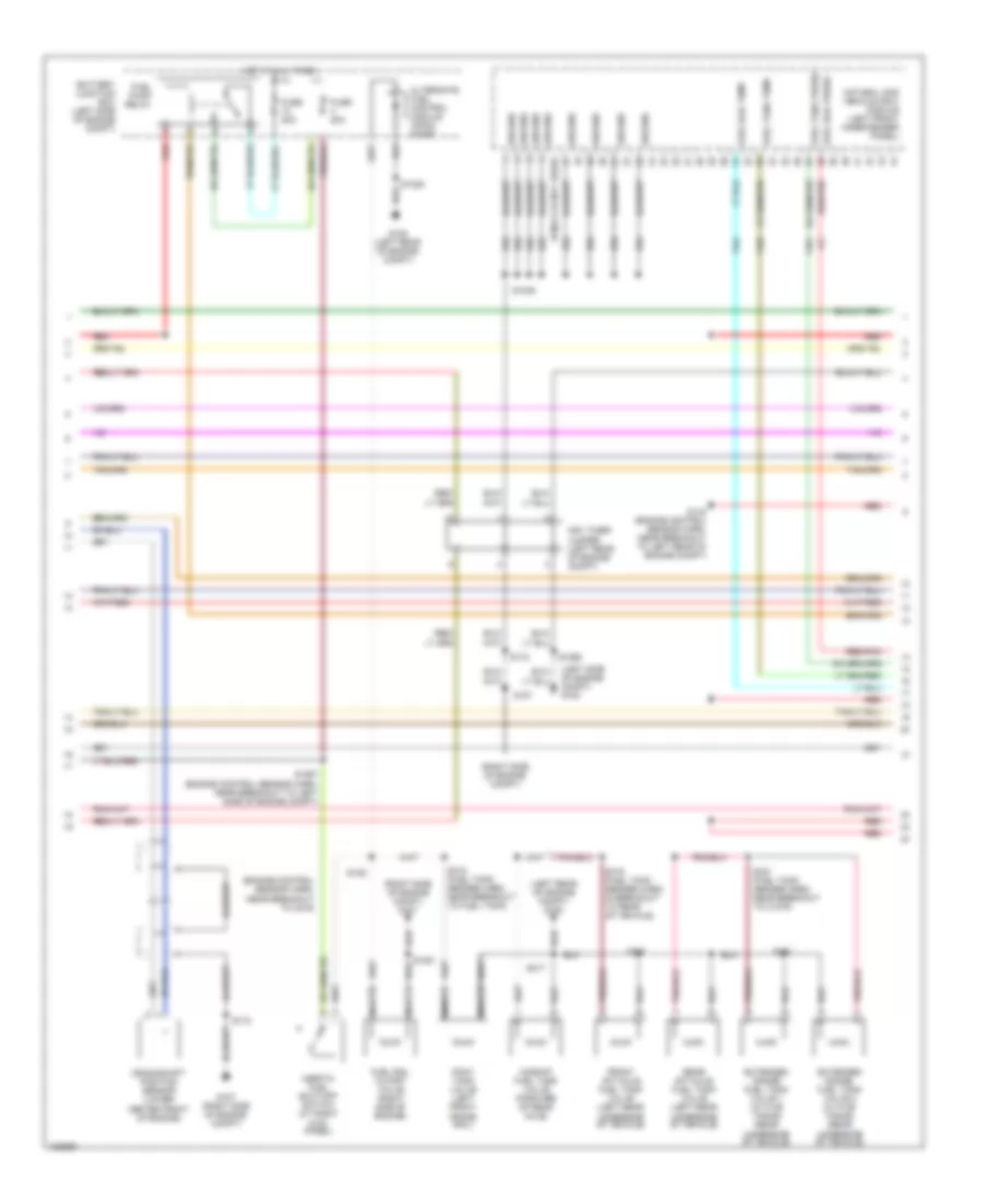
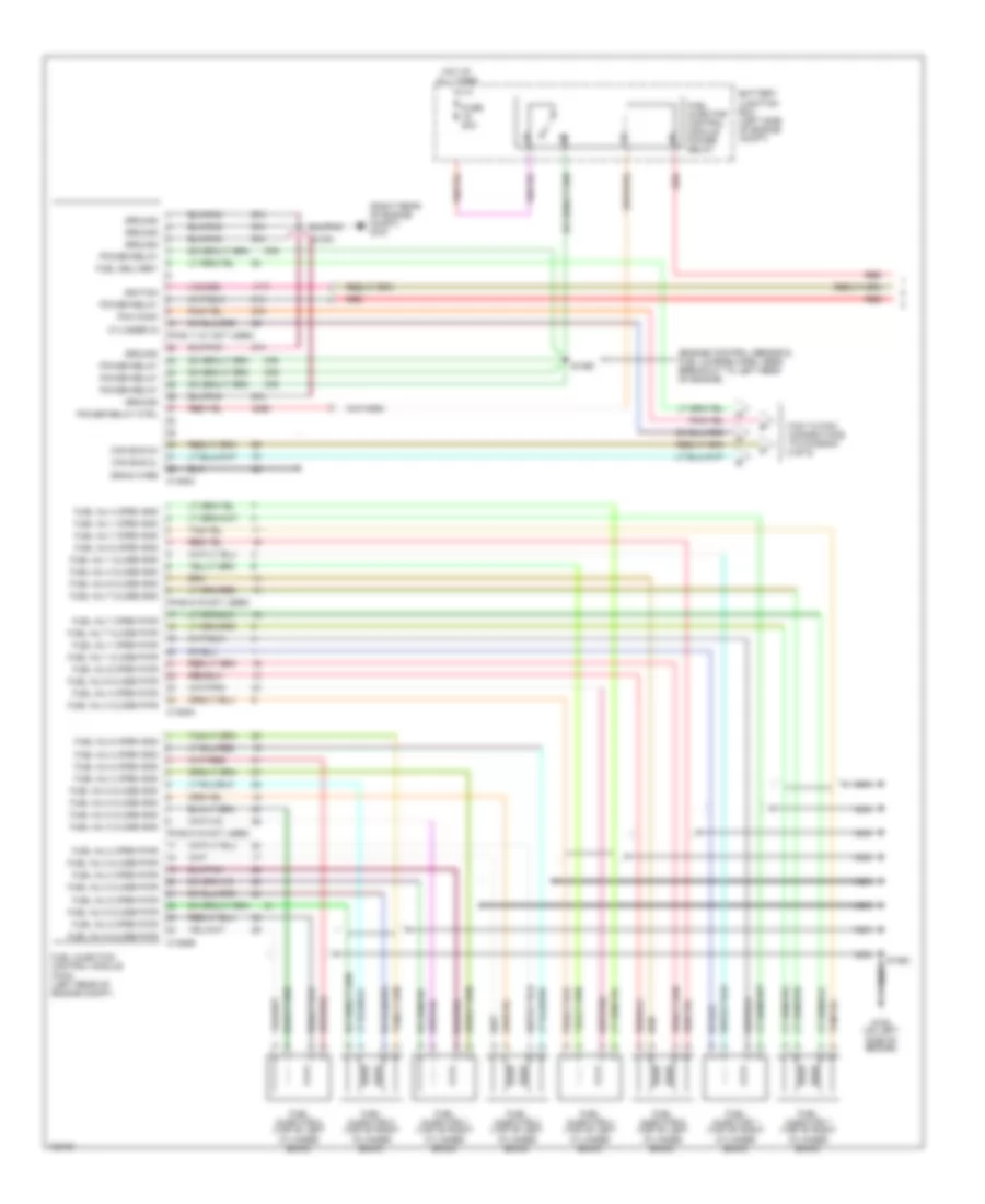
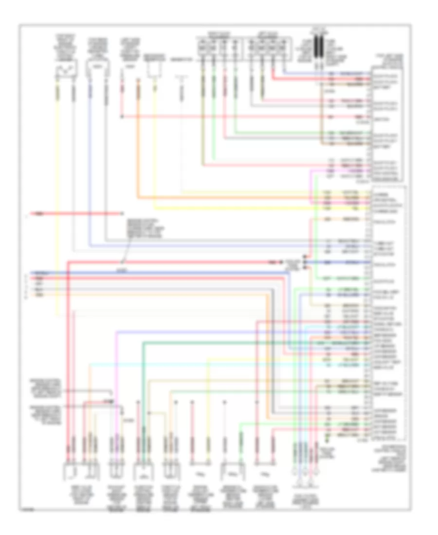
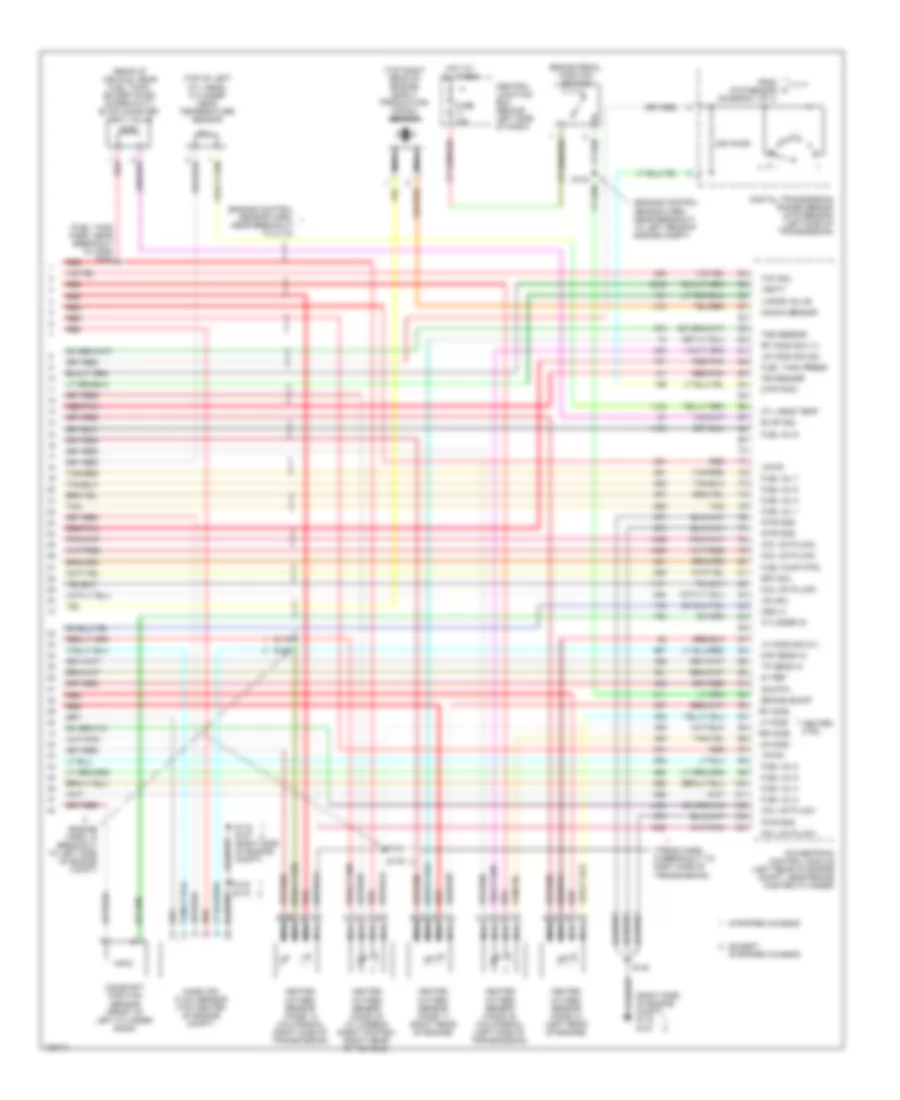
5.4L, Engine Performance Wiring Diagram (1 of 4) for Ford RV Cutaway E350 Super Duty 2004

List of elements for 5.4L, Engine Performance Wiring Diagram (1 of 4) for Ford RV Cutaway E350 Super Duty 2004:
- (ends in harness)
- (engine control sensor & fuel charge harn, at right side of engine)
- (engine control sensor & fuel charge harn, near breakout to left side of engine)
- (engine control sensor harn, near breakout to c237)
- (engine control sensor harn, near breakout to left rear of engine compt)
- (left front of engine, attached to ignition coil) ignition transformer capacitor 2
- (left side of engine compt)
- (right front of engine, attached to ignition coil) ignition transformer capacitor 1
- (right side of engine compt)
- (right side of engine compt) g107
- A/c on sig
- A/c system
- Battery junction box (left side of engine compt)
- Central junction box (behind left side of dash)
- Coast sol
- Coil on plug
- Coil on plug 1
- Coil on plug 3
- Coil on plug 4
- Coil on plug 5
- Coil on plug 6
- Data link (+)
- Data link (-)
- Data link connector (left side of dash)
- Digital transmission range sensor (dtr sensor) (left side of transmission)
- Dtr sensor (tr1)
- Dtr-tr2
- Dtr-tr4
- Evr sol
- Except stripped chassis
- Feps (eprom)
- Fuse 10a
- Fuse 30a
- G100
- G105
- G107
- G116
- Gnd
- Hot at all times
- Hot in run or start
- Knock sensor
- Maf
- Misfire sens (+)
- Misfire sens (-)
- Nca
- O/d off
- Overdrive cancel switch
- Pcm power diode
- Pcm power relay
- Powertrain control module (left rear of engine compt, near brake master cylinder)
- Pwr gnd
- R n
- Red
- Rr ho2s sig (12)
- S1033
- S1065
- S127
- S140
- S142
- S156
- S161
- S182
- S184
- S216
- Shift sol a
- Shift sol b
- Stripped chassis
- Tach sig
- Tcil ind
- Tcil lamp
- Tcs
- Tft
- To dtr sensor (diagram 4 of 4)
- Vpwr
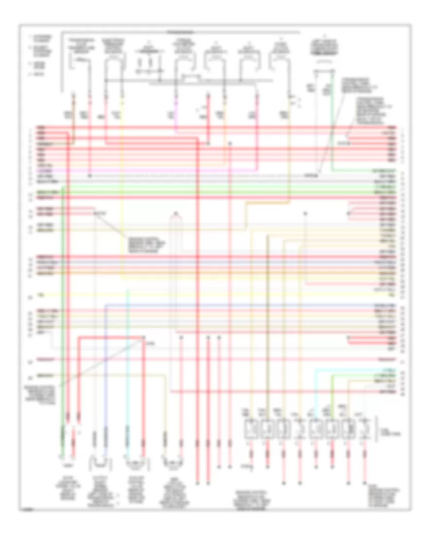
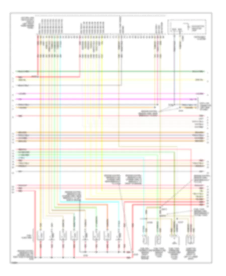
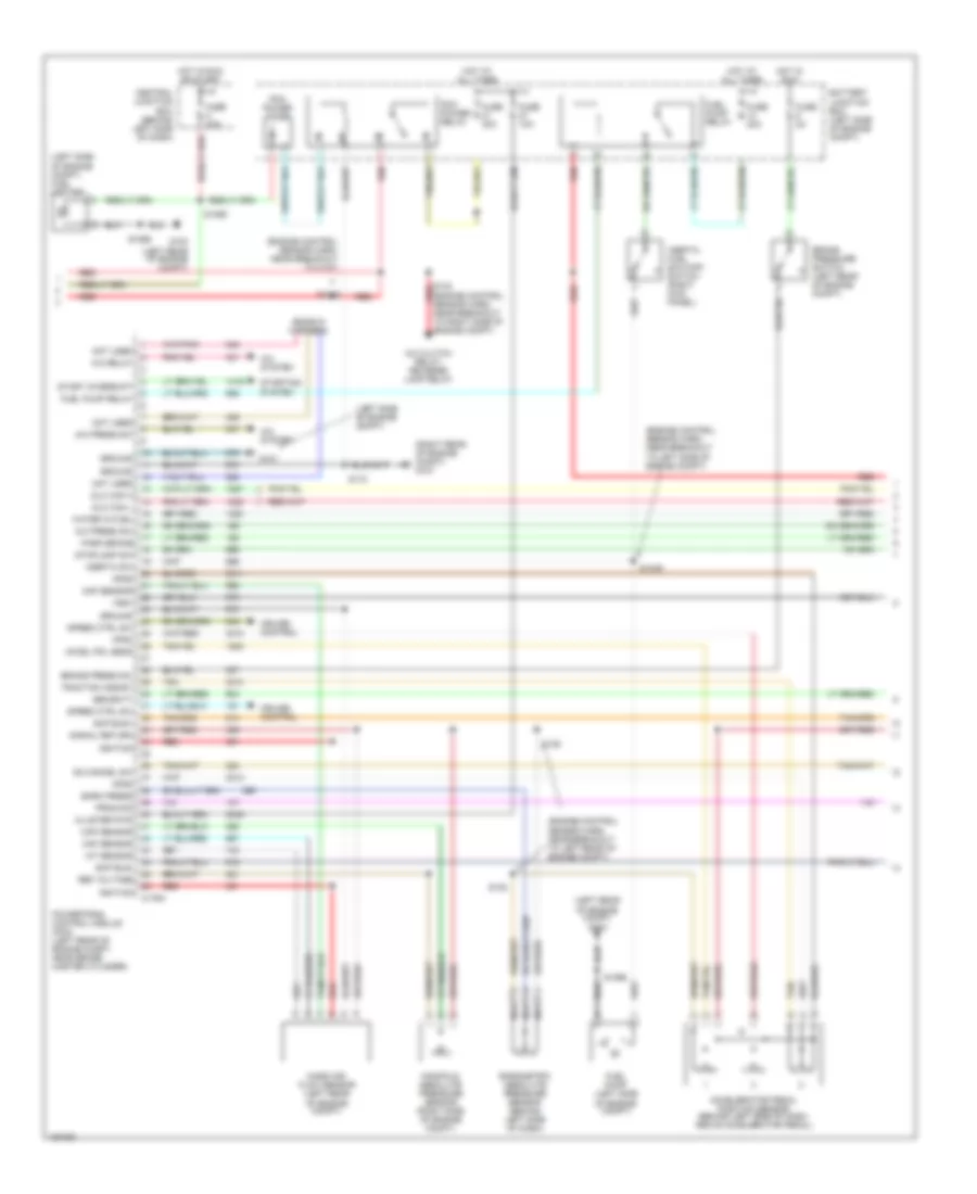
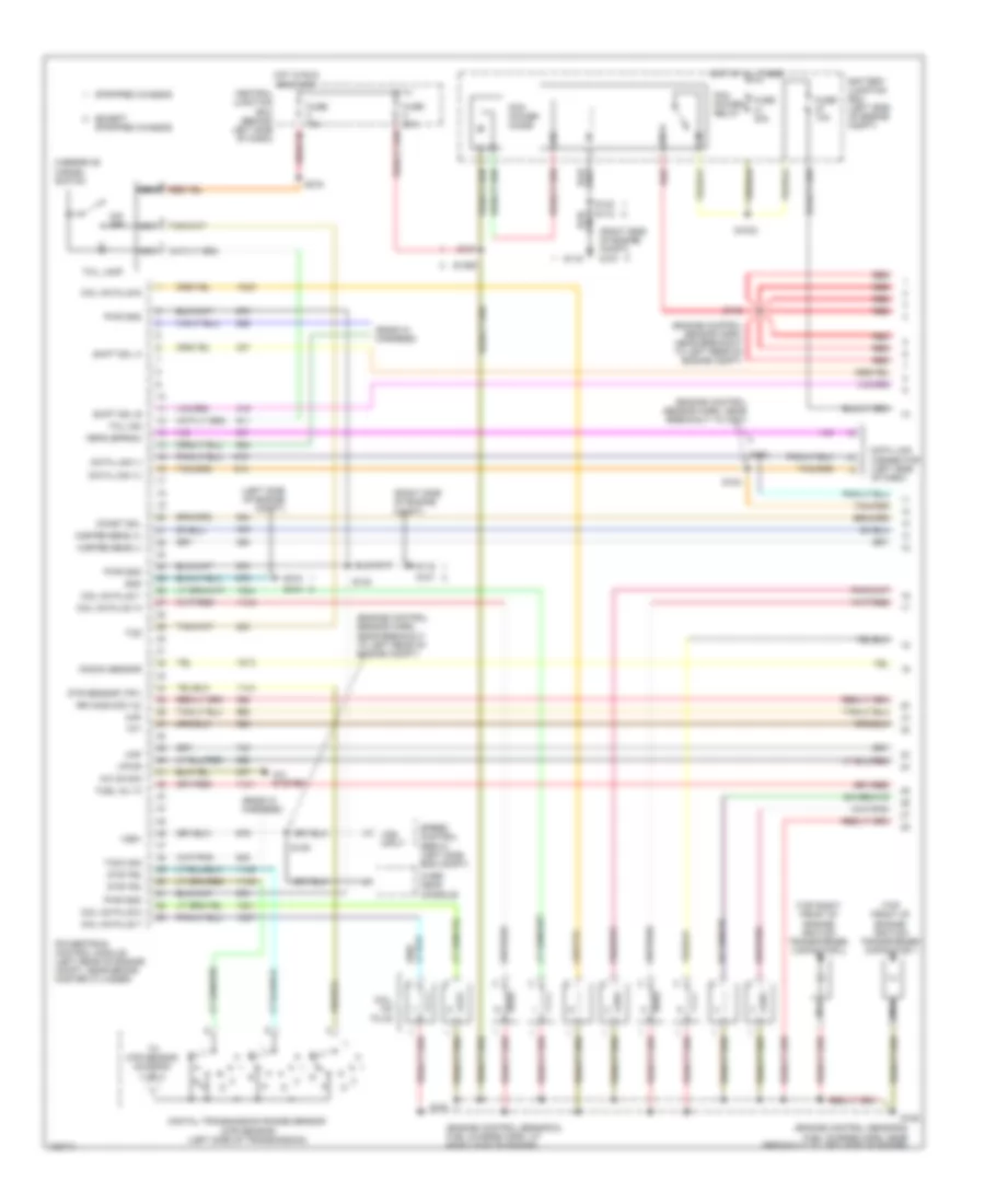
5.4L, Engine Performance Wiring Diagram (2 of 4) for Ford RV Cutaway E350 Super Duty 2004
List of elements for 5.4L, Engine Performance Wiring Diagram (2 of 4) for Ford RV Cutaway E350 Super Duty 2004:
- (engine control sensor harn, near breakout to c1033)
- (right side of engine compt)
- (right side of engine compt) g116 g107
- Battery junction box (left side of engine compt)
- Bus (+)
- Bus (-)
- Crankshaft position sensor (lower center front of engine)
- Differential pressure feedback egr sensor (california) (top left side of engine)
- Except stripped chassis
- Fuel level
- Fuel pump
- Fuel pump driver module (under rear of vehicle, near tank)
- Fuel pump relay
- Fuel tank pressure transducer (in fuel tank)
- Fuse 30a 20a
- G107
- G116
- G302 (under rear of vehicle)
- Hot at all times
- Inertia fuel shut-off switch (ex stripped chassis: at right kick panel) (stripped chassis: behind left side of dash)
- Injection pressure sensor (front of left cylinder bank)
- Instrument cluster
- Malfunction indicator lamp
- Red
- Red/pnk
- S138
- S140
- S157 (engine control sensor & fuel charge harn, at left center of engine)
- S158 (engine control sensor & fuel charge harn, near breakout to c1045)
- S172
- Stripped chassis
- Throttle position sensor (on top of engine, near air intake)
- Vref
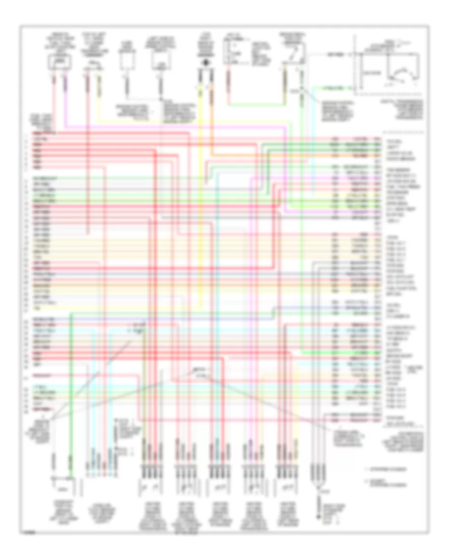
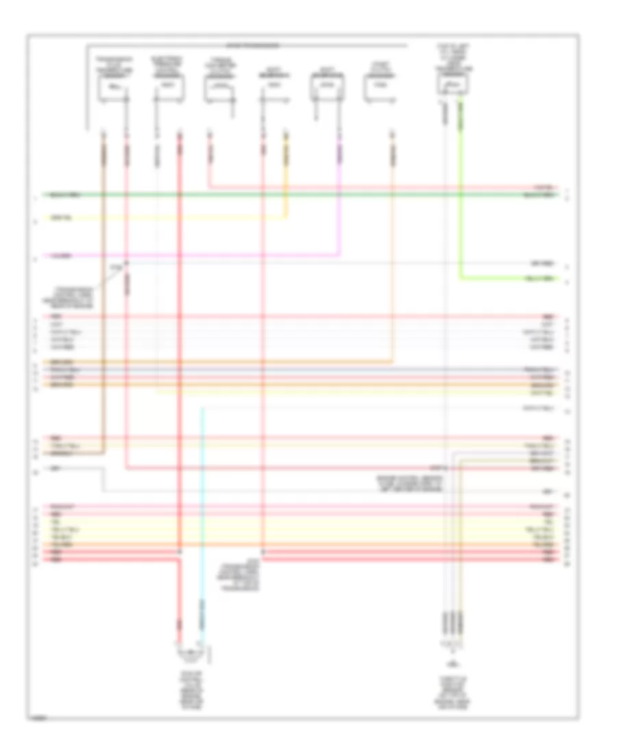
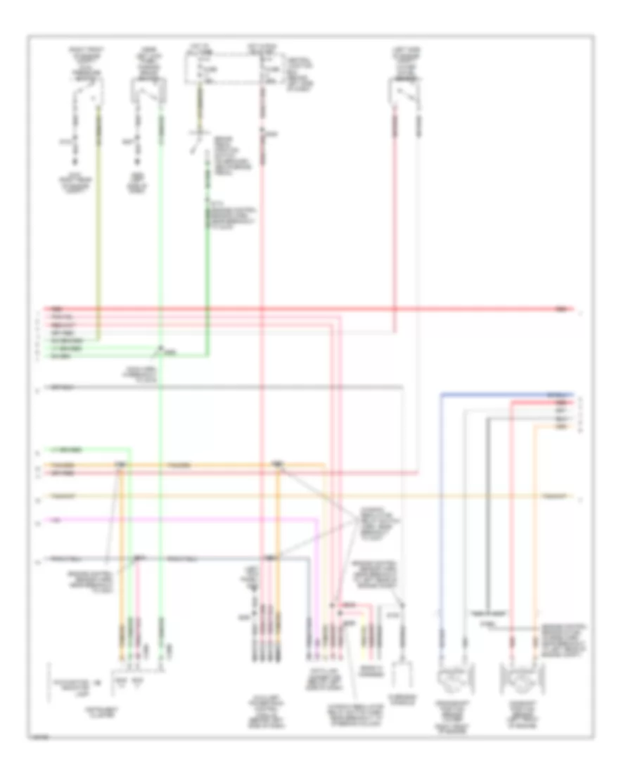
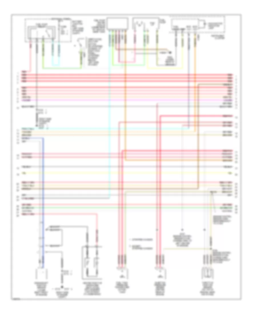
5.4L, Engine Performance Wiring Diagram (3 of 4) for Ford RV Cutaway E350 Super Duty 2004
List of elements for 5.4L, Engine Performance Wiring Diagram (3 of 4) for Ford RV Cutaway E350 Super Duty 2004:
- (engine control sensor & fuel charge harn, near breakout to c1045)
- (engine control sensor & fuel charge harn, near breakout to left side of engine)
- (engine control sensor harn, near breakout to left rear of engine)
- (left side of transmission) turbine shaft speed sensor
- (right rear of engine)
- (transmission control harn, near breakout at 4r70e/4r75e: rear of engine, 4r100: top of transmission)
- (transmission control harn, near breakout at rear of engine)
- 4r100
- 4r70e/ 4r75e
- Coast clutch solenoid
- Egr vacuum regulator solenoid (california) (above left rear of engine, on bracket)
- Electronic pressure control solenoid
- Evap canister purge valve
- Except stripped chassis
- Fuel injectors
- Idle air control valve (rear of engine, near air intake)
- Output shaft speed sensor (left side of transmission) (rear of transmission)
- Red
- Red/pnk
- S100
- S102
- S136
- S155
- S159
- S160 (engine control sensor & fuel charge harn, at right side of engine)
- Shift solenoid
- Shift solenoid a
- Shift solenoid b
- Stripped chassis
- Tan
- Tan/ red
- Tan/red
- Torque converter clutch solenoid
- Transmission
- Transmission fluid temperature sensor
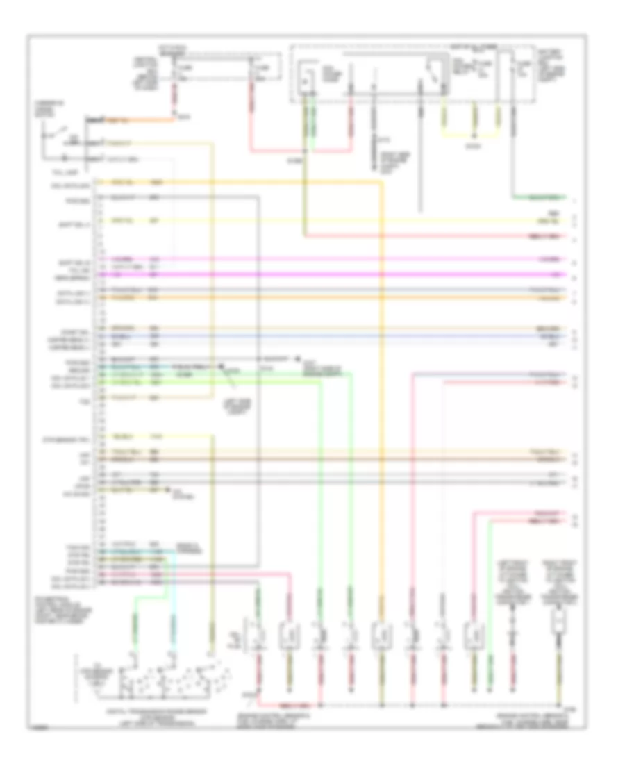
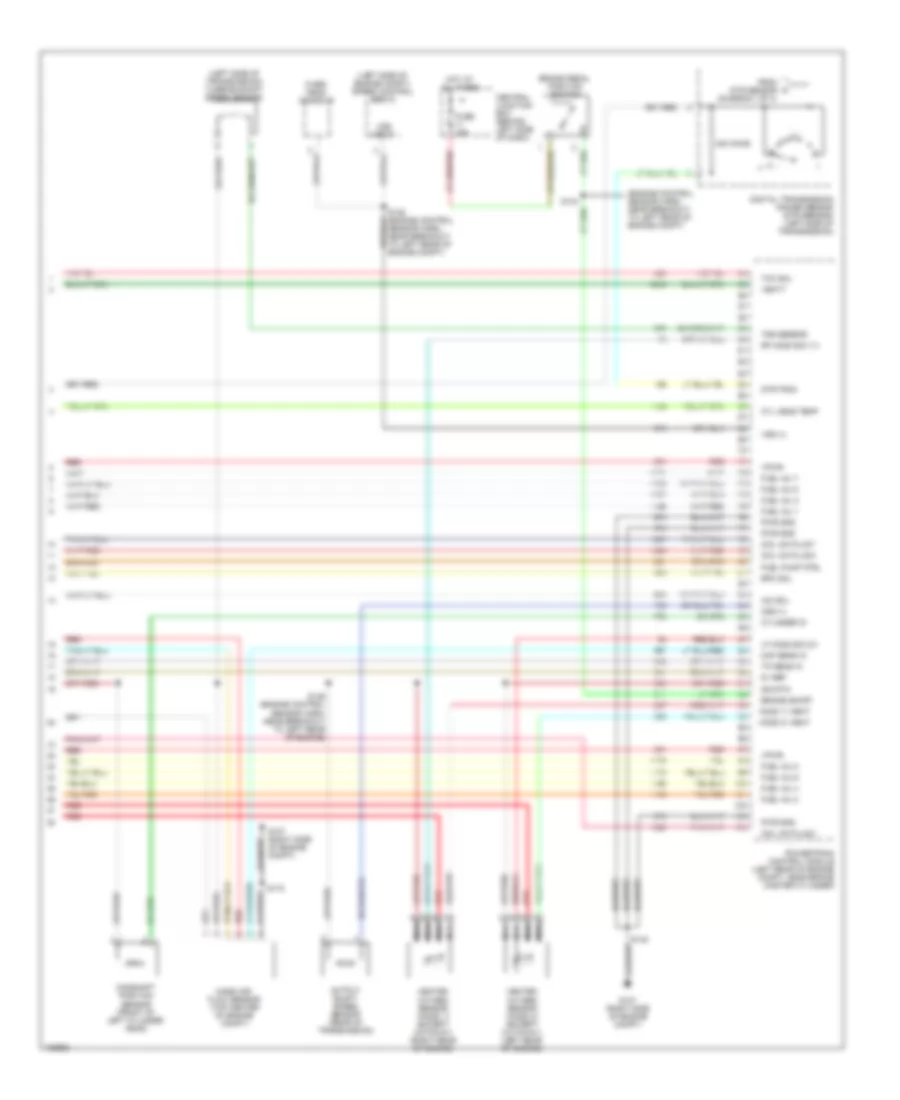
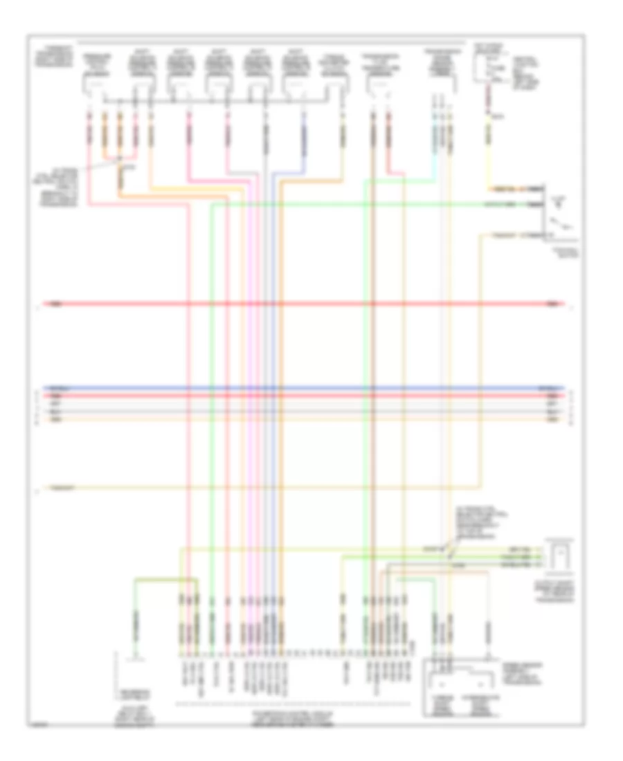
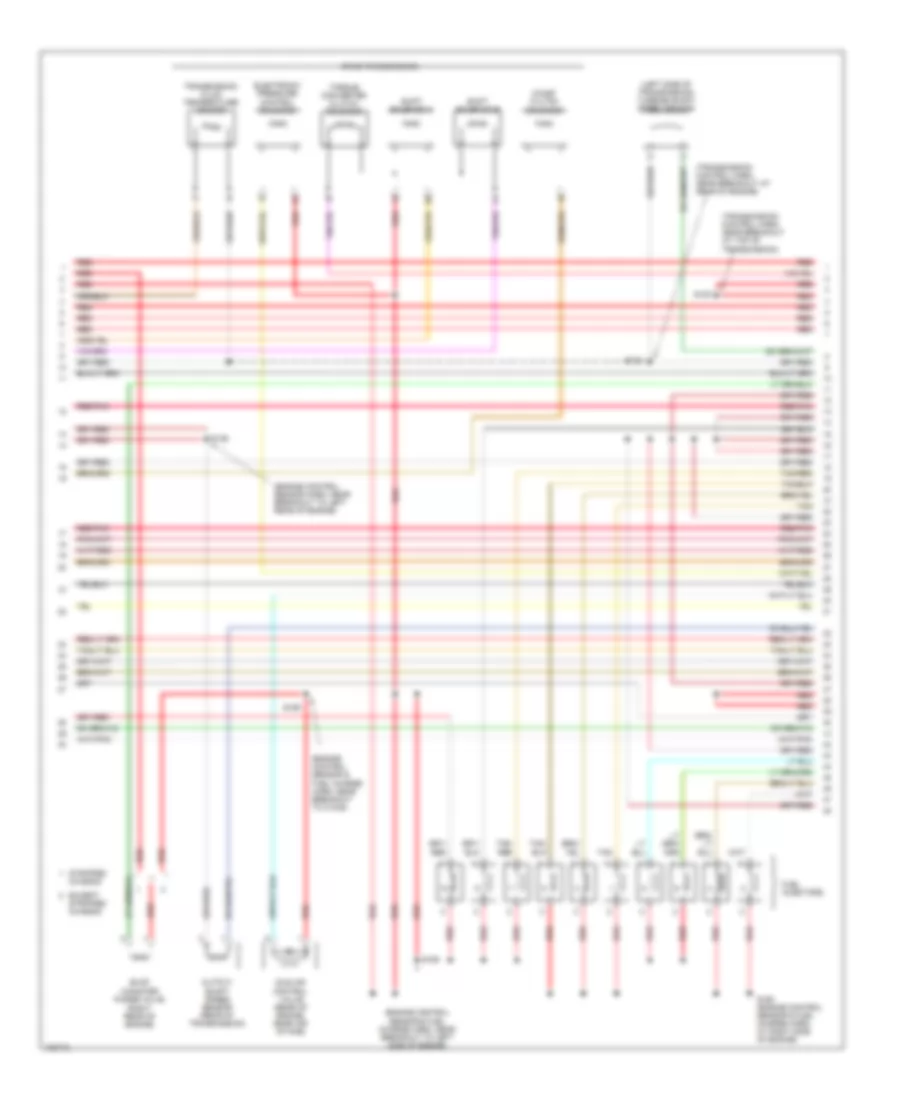
5.4L, Engine Performance Wiring Diagram (4 of 4) for Ford RV Cutaway E350 Super Duty 2004
List of elements for 5.4L, Engine Performance Wiring Diagram (4 of 4) for Ford RV Cutaway E350 Super Duty 2004:
- (engine control sensor harn, near breakout to c110)
- (engine control sensor harn, near breakout to left rear of engine compt)
- (engine harn, in breakout to left side of engine compt)
- (fuel tank harn, near breakout to c925) s324
- (left side of engine compt) speed control servo
- (rear of vehicle, near fuel tank) evap canister vent valve
- (right side of engine compt) g116 g107
- (top of left cyl head) cylinder head temperature sensor
- (top right rear of engine) knock sensor
- (trans harn, in breakout to right side of transmission)
- 240 ohms
- 5v ref
- Brake on/off
- Brake pedal position switch
- Camshaft position sensor (front of left cylinder head)
- Central junction box (behind left side of dash)
- Coil on plug 2
- Coil on plug 7
- Coil on plug 8
- Cyl head temp
- Cylinder id
- Digital transmission range sensor (dtr sensor) (left side of transmission)
- Dpfe sens
- Dtr-tr3a
- Epc sol
- Evap sol
- Except stripped chassis
- From dtr sensor (diagram 1 of 4)
- Fuel inj 1
- Fuel inj 2
- Fuel inj 3
- Fuel inj 4
- Fuel inj 5
- Fuel inj 6
- Fuel inj 7
- Fuel inj 8
- Fuel pump ctrl
- Fuel tank press
- Fuse 15a
- G116 g107 (right side of engine compt)
- Heated oxygen sensor (ho2s) 11 (right rear of engine)
- Heated oxygen sensor (ho2s) 12 (california) (right side of transmission)
- Heated oxygen sensor (ho2s) 21 (left rear of engine)
- Heated oxygen sensor (ho2s) 22 (california) (left side of transmission)
- Heated oxygen sensor (ho2s) 23 (w/ carbon mngmt system) (right rear of vehicle)
- Heater ctrl
- Hot at all times
- Iac sol
- Ips sensor
- Knock sensor
- Lf ho2s
- Lf ho2s sig (21)
- Lr ho2s
- Lr ho2s sig (22)
- Maf sens in
- Mass air- flow sensor (top center of engine compt)
- Nca
- Oss (+)
- Over- head console
- Powertrain control module (left rear of engine compt, near brake master cylinder)
- Pwr gnd
- Red
- Red/pnk
- Rf ho2s
- Rf ho2s sig (11)
- Rr ho2s
- S119
- S123
- S135 (engine control sensor harn, near breakout to left rear of engine compt)
- S140
- S172
- S179
- S186
- Sig rtn
- Stripped chassis
- Tan
- Tan/red
- Tcc sol
- Tp sens in
- Tss sensor
- Vapor valve
- Vbatt
- Vpwr
- Vss (+)
- Vss input
5.4L CNG
5.4L CNG, Engine Performance Wiring Diagram (1 of 5) for Ford RV Cutaway E350 Super Duty 2004
List of elements for 5.4L CNG, Engine Performance Wiring Diagram (1 of 5) for Ford RV Cutaway E350 Super Duty 2004:
- (ends in harness)
- (engine control sensor & fuel charge harn, at right side of engine)
- (engine control sensor & fuel charge harn, near breakout to left side of engine)
- (left front of engine, attached to ignition coil) ignition transformer capacitor 1
- (left side of engine compt)
- (right front of engine, attached to ignition coil) ignition transformer capacitor 2
- (right side of engine compt) g107
- A/c on sig
- A/c system
- Battery junction box (left side of engine compt)
- Central junction box (behind left side of dash)
- Coast sol
- Coil on plug
- Coil on plug 1
- Coil on plug 3
- Coil on plug 4
- Coil on plug 5
- Coil on plug 6
- Data link (+)
- Data link (-)
- Digital transmission range sensor (dtr sensor) (left side of transmission)
- Dtr sensor (tr1)
- Dtr-tr2
- Dtr-tr4
- Feps (eprom)
- Fuse 10a
- Fuse 30a
- G100
- G107 (right side of engine compt)
- Ground
- Hot at all times
- Hot in run or start
- Maf
- Misfire sens (+)
- Misfire sens (-)
- Nca
- O/d off
- Overdrive cancel switch
- Pcm power diode
- Pcm power relay
- Powertrain control module (left rear of engine compt, near brake master cylinder)
- Pwr gnd
- R n
- Red
- S1033
- S1065
- S1069
- S140
- S156
- S161
- S216
- Shift sol a
- Shift sol b
- Tach sig
- Tcil ind
- Tcil lamp
- Tcs
- Tft
- To dtr sensor (diagram 4 of 4)
- Vpwr
5.4L CNG, Engine Performance Wiring Diagram (2 of 5) for Ford RV Cutaway E350 Super Duty 2004
List of elements for 5.4L CNG, Engine Performance Wiring Diagram (2 of 5) for Ford RV Cutaway E350 Super Duty 2004:
- (engine control sensor harn, near breakout to c219)
- (left rear of engine compt) g105
- (left side of engine compt) g100
- (pins 5-16 not used)
- (right side of engine compt)
- (right side of engine compt) g107
- Alternate fuel control module (afcm) diode
- Battery junction box (left side of engine compt)
- Crankshaft position sensor (lower center front of engine)
- Extended range fuel tank valve 1 (w/ five tanks) (rear underside of vehicle)
- Extended range fuel tank valve 2 (w/ five tanks) (rear underside of vehicle)
- Front aft-axle fuel tank valve (left rear underside of vehicle)
- Fuel pump relay
- Fuel rail cutoff valve (right side of engine)
- Fuel rail press
- Fuel rail temp
- Fuel tank press
- Fuel tank temp
- Fuse 20a
- G105 (left rear of engine compt)
- G107
- G107 (right side of engine compt)
- Ground
- Hot at all times
- Inertia fuel shut-off switch (at right kick panel)
- Midship fuel tank valve (forward of rear axle)
- Natural gas vehicle (ngv) module (left front inner fender panel)
- Nca
- Ngv timer jumper (left rear of engine compt)
- Pony tank valve (left front frame rail)
- Rear aft-axle fuel tank valve (left rear underside of vehicle)
- Red
- Red/
- Red/pnk
- S1035
- S1051
- S1067 (engine control sensor harn, near breakout to left side of engine compt)
- S1069
- S142 (engine control sensor harn, near breakout to left rear of engine compt)
- S172
- S185
- S317
- S318 (fuel tank sender harn, near breakout to fuel tank)
- S319 (fuel tank sender harn, in breakout to rear of vehicle)
- S320
- S321 (fuel tank sender harn, near breakout to c1279)
- S322
5.4L CNG, Engine Performance Wiring Diagram (3 of 5) for Ford RV Cutaway E350 Super Duty 2004
List of elements for 5.4L CNG, Engine Performance Wiring Diagram (3 of 5) for Ford RV Cutaway E350 Super Duty 2004:
- (engine control sensor & fuel charge harn, at right side of engine) s160
- (engine control sensor & fuel charge harn, in breakout to front of engine)
- (engine control sensor & fuel charge harn, near breakout to c1045)
- (engine control sensor & fuel charge harn, near breakout to left side of engine)
- (engine control sensor harn, near breakout to c140)
- (engine control sensor harn, near breakout to c237)
- (fuel tank sender harn, near breakout to fuel tank)
- Bus (+)
- Bus (-)
- C220a
- Data link connector (left side of dash)
- Eec relay
- Fuel inj 1 ctrl
- Fuel inj 1 in
- Fuel inj 2 ctrl
- Fuel inj 2 in
- Fuel inj 3 ctrl
- Fuel inj 3 in
- Fuel inj 4 ctrl
- Fuel inj 4 in
- Fuel inj 5 ctrl
- Fuel inj 5 in
- Fuel inj 6 ctrl
- Fuel inj 6 in
- Fuel inj 7 ctrl
- Fuel inj 7 in
- Fuel inj 8 ctrl
- Fuel inj 8 in
- Fuel injectors
- Fuel rail temperature sensor (right bank of engine)
- Fuel tank press
- Fuel tank pressure transducer sensor (in fuel tank)
- Fuel tank temperature sensor (in fuel tank)
- Ground
- Injection pressure sensor (front of left cylinder bank)
- Instrument cluster
- Malfunction indicator lamp
- Natural gas vehicle (ngv) module (left front inner fender panel)
- Red
- Red/pnk
- S1037
- S1050
- S1070
- S155
- S159
- S182
- S184
- S2013
- Scp bus +
- Scp bus -
- Sig return
- Tan
- Tan/red
5.4L CNG, Engine Performance Wiring Diagram (4 of 5) for Ford RV Cutaway E350 Super Duty 2004
List of elements for 5.4L CNG, Engine Performance Wiring Diagram (4 of 5) for Ford RV Cutaway E350 Super Duty 2004:
- (engine control sensor & fuel charge harn, at left center of engine)
- (top of left cyl head) cylinder head temperature sensor
- (transmission control harn, near breakout at rear of engine)
- 4r100 transmission
- Coast clutch solenoid
- Electronic pressure control solenoid
- Idle air control valve (rear of engine, near air intake)
- Red
- S100 (transmission control harn, near breakout at top of transmission)
- S102
- S157
- Shift solenoid a
- Shift solenoid b
- Throttle position sensor (on top of engine, near air intake)
- Torque converter clutch solenoid
- Transmission fluid temperature sensor
5.4L CNG, Engine Performance Wiring Diagram (5 of 5) for Ford RV Cutaway E350 Super Duty 2004
List of elements for 5.4L CNG, Engine Performance Wiring Diagram (5 of 5) for Ford RV Cutaway E350 Super Duty 2004:
- (engine control sensor harn, near breakout to left rear of engine compt)
- (left side of engine compt) speed control servo
- (left side of transmission) turbine shaft speed sensor
- 240 ohms
- 5v ref
- Brake on/off
- Brake pedal position switch
- Camshaft position sensor (front of left cylinder head)
- Central junction box (behind left side of dash)
- Coil on plug 2
- Coil on plug 7
- Coil on plug 8
- Cyl head temp
- Cylinder id
- Digital transmission range sensor (dtr sensor) (left side of transmission)
- Dtr-tr3a
- Epc sol
- From dtr sensor (diagram 1 of 4)
- Fuel inj 1
- Fuel inj 2
- Fuel inj 3
- Fuel inj 4
- Fuel inj 5
- Fuel inj 6
- Fuel inj 7
- Fuel inj 8
- Fuel pump ctrl
- Fuse 15a
- G107 (right side of engine compt)
- Heated oxygen sensor (ho2s) 11 (except cutaway) (right rear of engine)
- Heated oxygen sensor (ho2s) 21 (except cutaway) (left rear of engine)
- Ho2s 11 heat
- Ho2s 21 heat
- Hot at all times
- Iac sol
- Lf ho2s sig (21)
- Maf sens in
- Mass air- flow sensor (top center of engine compt)
- Nca
- Oss (+)
- Output shaft speed sensor (rear of transmission)
- Over- head console
- Powertrain control module (left rear of engine compt, near brake master cylinder)
- Pwr gnd
- Red
- Rf ho2s sig (11)
- S135 (engine control sensor harn, near breakout to left rear of engine compt)
- S136 (engine control sensor harn, near breakout to left rear of engine)
- S140
- S172
- Sig rtn
- Tcc sol
- Tp sens in
- Tss sensor
- Vbatt
- Vpwr
- Vss (+)
- Vss input
6.0L DIESEL
6.0L Diesel, Engine Performance Wiring Diagram (1 of 5) for Ford RV Cutaway E350 Super Duty 2004
List of elements for 6.0L Diesel, Engine Performance Wiring Diagram (1 of 5) for Ford RV Cutaway E350 Super Duty 2004:
- (engine control sensor & fuel charge harn, near breakout to left rear of engine)
- (pins 11-21 not used)
- (pins 9-16 not used)
- (right rear of engine compt) g107
- Battery junction box (left side of engine compt)
- C1388a
- C1388b
- C1388c
- Can bus 2h
- Can bus 2l
- Cylinder id
- Drain wire
- Ficm to pcm connections (to diagram 5 of 5)
- Fuel delivery
- Fuel inj 1 close gnd
- Fuel inj 1 close pwr
- Fuel inj 1 open gnd
- Fuel inj 1 open pwr
- Fuel inj 2 close gnd
- Fuel inj 2 close pwr
- Fuel inj 2 open gnd
- Fuel inj 2 open pwr
- Fuel inj 3 close gnd
- Fuel inj 3 close pwr
- Fuel inj 3 open gnd
- Fuel inj 3 open pwr
- Fuel inj 4 close gnd
- Fuel inj 4 close pwr
- Fuel inj 4 open gnd
- Fuel inj 4 open pwr
- Fuel inj 5 close gnd
- Fuel inj 5 close pwr
- Fuel inj 5 open gnd
- Fuel inj 5 open pwr
- Fuel inj 6 close gnd
- Fuel inj 6 close pwr
- Fuel inj 6 open gnd
- Fuel inj 6 open pwr
- Fuel inj 7 close gnd
- Fuel inj 7 close pwr
- Fuel inj 7 open gnd
- Fuel inj 7 open pwr
- Fuel inj 8 close gnd
- Fuel inj 8 close pwr
- Fuel inj 8 open gnd
- Fuel inj 8 open pwr
- Fuel injection control module (ficm) (left rear of engine compt)
- Fuel injector 1 (top of right cylinder bank)
- Fuel injector 2 (top of left cylinder bank)
- Fuel injector 3 (top of right cylinder bank)
- Fuel injector 4 (top of left cylinder bank)
- Fuel injector 5 (top of right cylinder bank)
- Fuel injector 6 (top of left cylinder bank)
- Fuel injector 7 (top of right cylinder bank)
- Fuel injector 8 (top of left cylinder bank)
- Fuel injector control module power relay
- Fuse 50a
- G108 (on left side of engine)
- Ground
- Hot at all times
- Ignition
- Nca
- Pcm comm
- Power relay
- Power relay ctrl
- Red
- S1060
- S1061
- S1062
6.0L Diesel, Engine Performance Wiring Diagram (2 of 5) for Ford RV Cutaway E350 Super Duty 2004
List of elements for 6.0L Diesel, Engine Performance Wiring Diagram (2 of 5) for Ford RV Cutaway E350 Super Duty 2004:
- (ends in harness)
- (engine control sensor harn, near breakout to c127)
- (engine control sensor harn, near breakout to left rear of engine compt)
- (engine control sensor harn, near breakout to left side of engine compt)
- (left rear of engine compt) g100
- (left side of engine compt)
- (left side of engine compt) fuel heater
- (right rear of engine compt) g107
- A/c clutch relay, reverse lamp relay
- A/c press sw
- A/c relay
- A/c system
- Accel pdl sens
- Accelerator pedal position sensor (behind left side of dash, above accelerator pedal)
- Aps2
- Aps3
- Baro press
- Barometric absolute pressure sensor (behind left side of dash)
- Battery junction box (left side of engine compt)
- Brake press sw
- Brake pressure switch (left rear of engine compt)
- C176a
- Central junction box (behind left side of dash)
- Cluster pwr
- Cruise control
- Dlc can h
- Dlc can l
- Fuel pump (left side of engine compt)
- Fuel pump relay
- Fuse 10a
- Fuse 20a
- Fuse 2a
- Fuse 30a
- G100 (left rear of engine compt)
- G121
- Gen/batt
- Ground
- Hot at all times
- Hot in run
- Hot in run or start
- Iat sensor
- Ignition
- Inertia fuel shutoff switch (right kick panel)
- Inertia sw
- Maf sensor
- Manifold absolute pressure sensor (right side of engine compt)
- Map sensor
- Mass air- flow sensor (left rear of engine compt)
- Nca
- Not used
- Od cancel sw
- Park brake
- Pcm power diode
- Pcm power relay
- Powertrain control module (pcm) (left rear of engine compt, near brake master cylinder)
- Prog sig
- Red
- Ref voltage
- S1049
- S1065
- S1066
- S1068
- S136
- S138
- S142 red (engine control sensor harn, near breakout to right side of engine compt)
- S172
- Scp bus+
- Scp bus-
- Signal return
- Speed ctrl sw
- Start interrupt
- Starting system
- Stoplamp sw
- Tan
- Traction assist
- Vss+
- Water in fuel
6.0L Diesel, Engine Performance Wiring Diagram (3 of 5) for Ford RV Cutaway E350 Super Duty 2004
List of elements for 6.0L Diesel, Engine Performance Wiring Diagram (3 of 5) for Ford RV Cutaway E350 Super Duty 2004:
- (ends in harness)
- (engine control sensor & fuel charge harn, near breakout to left rear of engine compt)
- (engine control sensor harn, near breakout to c237)
- (engine control sensor harn, near breakout to left rear of engine compt)
- (left kick panel) g204
- (left side of engine compt) water- in-fuel sensor
- (main harn, in breakout to c219)
- (near left kick panel) parking brake switch
- (right front of engine compt) dual pressure switch
- (window regulator relay switch harn, near breakout to c237)
- (window regulator relay switch harn, near breakout to steering column)
- Auxiliary powertrain control module (behind left side of dash)
- Brake pedal position switch (on bracket, above brake pedal)
- Bus (+)
- Bus (-)
- C220a
- C220b
- Camshaft position sensor (left front of engine)
- Central junction box (behind left side of dash)
- Crankshaft position sensor (lower
- Data link connector (below left side of dash)
- Fuse 15a
- Fuse 30a
- G107 (right rear of engine compt)
- G202 (left side of dash)
- Hot at all times
- Hot in run or start
- Instrument cluster
- Malfunction indicator lamp
- Nca
- Overhead console
- Red
- Right front of engine)
- S1064
- S135
- S182
- S184
- S228
- S250
- S262
- S263
- S268
- S269
- Sensor harn, near breakout to c219)
6.0L Diesel, Engine Performance Wiring Diagram (4 of 5) for Ford RV Cutaway E350 Super Duty 2004
List of elements for 6.0L Diesel, Engine Performance Wiring Diagram (4 of 5) for Ford RV Cutaway E350 Super Duty 2004:
- (in trans ctrl selector neutral switch harn, in breakout to right side of transmission)
- (in trans ctrl selector neutral switch harn, near breakout to top of transmission)
- Auxiliary relay box 1 (right rear of engine compt)
- C176b
- Central junction box (behind left side of dash)
- Fuse 10a
- Hot in run or start
- Illum
- Intermediate shaft speed sensor
- Iss sig
- Nca
- Oss sig
- Output shaft speed sensor (at rear of transmission)
- Pc sol pwr
- Pc-a sol
- Powertrain control module (left rear of engine compt, near brake master cylinder)
- Pressure control (pc-a) solenoid
- Red
- Ref volt
- Rev lmp ctrl
- Reversing lamp relay
- S1037
- S123
- S198
- S216
- Shift solenoid pressure control a (sspc-a)
- Shift solenoid pressure control b (sspc-b)
- Shift solenoid pressure control c (sspc-c)
- Shift solenoid pressure control d (sspc-d)
- Shift solenoid pressure control e (sspc-e)
- Sig trn
- Speed sensor assembly (left side of transmission)
- Sspc-a crl
- Sspc-b ctrl
- Sspc-c crl
- Sspc-d ctrl
- Sspc-e ctrl
- Tcc sol ctrl
- Tcil ctrl
- Tft sens sig
- Torqshift transmission (right side of transmission)
- Torque converter clutch solenoid
- Tow/haul switch
- Tr-p gnd
- Tr-p sig
- Transmission fluid temperature sensor
- Transmission range sensor assembly (tr-p)
- Tss sig
- Turbine shaft speed sensor
6.0L Diesel, Engine Performance Wiring Diagram (5 of 5) for Ford RV Cutaway E350 Super Duty 2004
List of elements for 6.0L Diesel, Engine Performance Wiring Diagram (5 of 5) for Ford RV Cutaway E350 Super Duty 2004:
- (engine control sensor & fuel charge harn, near breakout to top center of engine)
- (engine control sensor harn, near breakout to left front of engine)
- (engine control sensor harn, near breakout to left rear of engine compt)
- (left side of engine compt) injection pressure sensor
- (top left side of engine) glow plug control module
- (top rear of engine) variable geometric turbo actuator
- (top right front of engine) electronic throttle control motor
- Act sensor
- Battery
- C1301a
- C1301b
- C176c
- Can bus 2h
- Can bus 2l
- Charge
- Charge (2nd)
- Ckp sensor
- Cmp sensor
- Coolant temp
- Cooling fan
- Cooling fans system
- Ebp sensor
- Egr tp sensor
- Egr valve
- Egr valve actuator (top center front of engine)
- Engine coolant temperature sensor (upper
- Engine oil temperature sensor (center right side of engine)
- Eot sensor
- Etc motor
- Exhaust back pressure sensor (top center of engine)
- Fan clutch
- Ficm comm
- Ficm cyl id
- Ficm delivery
- Ficm to pcm connections (from diagram 1 of 5)
- Fuse link h 12 gauge gray (top of engine)
- Fuse link i 12 gauge gray (right side of engine compt)
- Generator
- Glow plug
- Glow plug 1
- Glow plug 2
- Glow plug 3
- Glow plug 4
- Glow plug 5
- Glow plug 6
- Glow plug 7
- Glow plug 8
- Glow plug sys
- Ground
- Hot at all times
- Icp sensor
- Ignition
- Injection control pressure sensor (center rear of engine)
- Ipr control
- Left front of engine)
- Left glow plug bank
- Manifold air temperature sensor (lower left side of engine)
- Pcm control
- Pcm monitor
- Powertrain control module (pcm) (left rear of engine compt, near brake master cylinder)
- Red
- Ref voltage
- Right glow plug bank
- S1054
- S1057
- S1058
- S1059
- Secondary generator
- Signal return
- Throttle position sensor (top of engine, near air intake)
- Turbo act
6.8L
6.8L, Engine Performance Wiring Diagram (1 of 4) for Ford RV Cutaway E350 Super Duty 2004
List of elements for 6.8L, Engine Performance Wiring Diagram (1 of 4) for Ford RV Cutaway E350 Super Duty 2004:
- (ends in harness)
- (engine control sensor & fuel charge harn, at right side of engine)
- (engine control sensor & fuel charge harn, near breakout to left side of engine)
- (engine control sensor harn, near breakout to c237)
- (engine control sensor harn, near breakout to left rear of engine compt)
- (left side of engine compt)
- (right side of engine compt)
- (right side of engine compt) g107
- (top front of engine) ignition transformer capacitor 1
- (top right front of engine) ignition transformer capacitor 2
- A/c on sig
- A/c system
- Battery junction box (left side of engine compt)
- Central junction box (behind left side of dash)
- Coast sol
- Coil on plug
- Coil on plug 1
- Coil on plug 10
- Coil on plug 5
- Coil on plug 6
- Coil on plug 7
- Data link (+)
- Data link (-)
- Data link connector (left side of dash)
- Digital transmission range sensor (dtr sensor) (left side of transmission)
- Dtr sensor (tr1)
- Dtr-tr2
- Dtr-tr4
- Except stripped chassis
- Feps (eprom)
- Fuel inj 10
- Fuse 10a
- Fuse 30a
- G100
- G105
- G107
- G116
- Gnd
- Hot at all times
- Hot in run or start
- Knock sensor
- Maf
- Misfire sens (+)
- Misfire sens (-)
- Nca
- O/d off
- Over- head console
- Overdrive cancel switch
- Pcm power diode
- Pcm power relay
- Powertrain control module (left rear of engine compt, near brake master cylinder)
- Pwr gnd
- R n
- Red
- Rr ho2s sig (12)
- S1033
- S1065
- S127
- S135
- S140
- S142
- S161
- S162
- S182
- S184
- S216
- Shift sol a
- Shift sol b
- Speed control servo (left side eng compt)
- Stripped chassis
- Tach sig
- Tcil ind
- Tcil lamp
- Tcs
- Tft
- To dtr sensor (diagram 4 of 4)
- Vpwr
- Vss input
- Vss+
6.8L, Engine Performance Wiring Diagram (2 of 4) for Ford RV Cutaway E350 Super Duty 2004
List of elements for 6.8L, Engine Performance Wiring Diagram (2 of 4) for Ford RV Cutaway E350 Super Duty 2004:
- (engine control sensor harn, near breakout to c1033)
- (right side of engine compt)
- (right side of engine compt) g116 g107
- Battery junction box (left side of engine compt)
- Bus (+)
- Bus (-)
- Crankshaft position sensor (lower right front of engine)
- Except stripped chassis
- Fuel level
- Fuel pump
- Fuel pump driver module (under rear of vehicle, near tank)
- Fuel pump relay
- Fuel tank pressure transducer (in fuel tank)
- Fuse 30a 20a
- G107
- G116
- G302 (under rear of vehicle)
- Heated positive crankcase ventilation (pcv) element (top of right cylinder bank)
- Hot at all times
- Inertia fuel shut-off switch (ex stripped chassis: at right kick panel) (stripped chassis: behind left side of dash)
- Injection pressure sensor (center rear of engine)
- Instrument cluster
- Malfunction indicator lamp
- Nca
- Red
- Red/pnk
- S138
- S140
- S157 (engine control sensor & fuel charge harn, at left center of engine)
- S158 (engine control sensor & fuel charge harn, near breakout to c1045)
- S172
- Stripped chassis
- Throttle position sensor (on top of engine, near air intake)
- Vref
6.8L, Engine Performance Wiring Diagram (3 of 4) for Ford RV Cutaway E350 Super Duty 2004
List of elements for 6.8L, Engine Performance Wiring Diagram (3 of 4) for Ford RV Cutaway E350 Super Duty 2004:
- (engine control sensor & fuel charge harn, near breakout to c1045)
- (engine control sensor & fuel charge harn, near breakout to left side of engine)
- (engine control sensor harn, near breakout to left rear of engine)
- (left side of transmission) turbine shaft speed sensor
- (right rear of engine)
- (transmission control harn, near breakout at rear of engine)
- (transmission control harn, near breakout at top of transmission)
- 4r100 transmission
- Coast clutch solenoid
- Electronic pressure control solenoid
- Evap canister purge valve
- Except stripped chassis
- Fuel injectors
- Idle air control valve (rear of engine, near air intake)
- Output shaft speed sensor (rear of transmission)
- Red
- Red/pnk
- S100
- S102
- S136
- S155
- S159
- S160 (engine control sensor & fuel charge harn, at right side of engine)
- Shift solenoid a
- Shift solenoid b
- Stripped chassis
- Tan
- Tan/ red
- Tan/red
- Torque converter clutch solenoid
- Transmission fluid temperature sensor
6.8L, Engine Performance Wiring Diagram (4 of 4) for Ford RV Cutaway E350 Super Duty 2004
List of elements for 6.8L, Engine Performance Wiring Diagram (4 of 4) for Ford RV Cutaway E350 Super Duty 2004:
- (engine control sensor harn,
- (engine control sensor harn, near breakout to left rear of engine compt)
- (engine harn, in breakout to left side of engine compt)
- (fuel tank harn, near breakout to c925) s324
- (rear of vehicle, near fuel tank) (except e-450 super duty) evap canister vent valve
- (right side of engine compt) g116 g107
- (top of left cyl head) cylinder head temperature sensor
- (top right rear of engine) (early production) knock sensor
- (trans harn, in breakout to right side of transmission)
- 240 ohms
- 5v ref
- Brake on/off
- Brake pedal position switch
- Camshaft position sensor (front of left cylinder bank)
- Central junction box (behind left side of dash)
- Coil on plug 2
- Coil on plug 3
- Coil on plug 4
- Coil on plug 8
- Coil on plug 9
- Cyl head temp
- Cylinder id
- Digital transmission range sensor (dtr sensor) (left side of transmission)
- Dtr-tr3a
- Epc sol
- Evap sol
- Except stripped chassis
- From dtr sensor (diagram 1 of 4)
- Fuel inj 1
- Fuel inj 2
- Fuel inj 3
- Fuel inj 4
- Fuel inj 5
- Fuel inj 6
- Fuel inj 7
- Fuel inj 8
- Fuel inj 9
- Fuel pump ctrl
- Fuel tank press
- Fuse 15a
- G116 g107 (right side of engine compt)
- Heated oxygen sensor (ho2s) 11 (right rear of engine)
- Heated oxygen sensor (ho2s) 12 (california) (right side of transmission)
- Heated oxygen sensor (ho2s) 21 (left rear of engine)
- Heated oxygen sensor (ho2s) 22 (california) (left side of transmission)
- Heated oxygen sensor (ho2s) 23 (w/ carbon mngmt system) (right rear of vehicle)
- Heater ctrl
- Hot at all times
- Iac sol
- Ips sensor
- Knock sensor
- Lf ho2s
- Lf ho2s sig (21)
- Lr ho2s
- Lr ho2s sig (22)
- Maf sens in
- Mass air- flow sensor (top center of engine compt)
- Nca
- Near breakout to c110)
- Oss (+)
- Powertrain control module (left rear of engine compt, near brake master cylinder)
- Pwr gnd
- Red
- Red/pnk
- Rf ho2s
- Rf ho2s sig (11)
- Rr ho2s
- S119
- S123
- S140
- S172
- S179
- S186
- Sig rtn
- Stripped chassis
- Tan
- Tan/red
- Tcc sol
- Tp sens in
- Tss sensor
- Vapor valve
- Vbatt
- Vpwr