ENGINE PERFORMANCE
3.0L
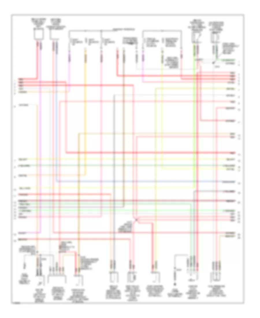
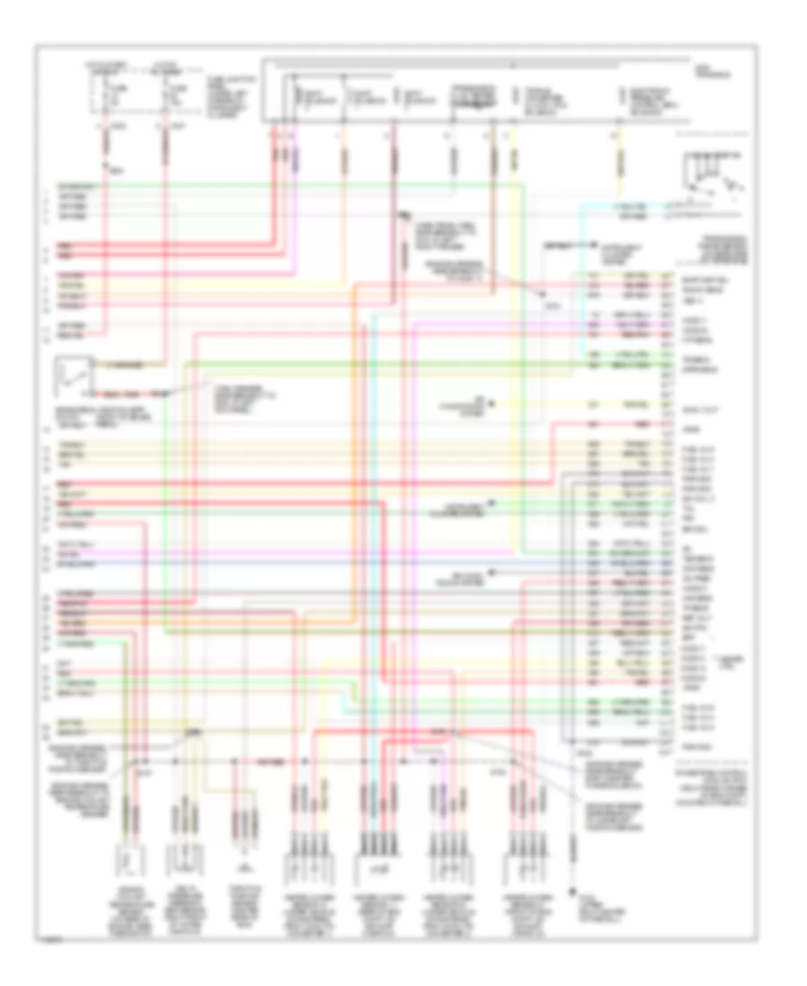
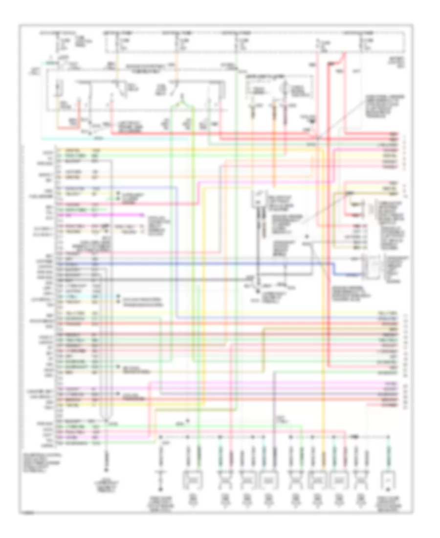
3.0L 12-Valve, Engine Performance Wiring Diagrams (1 of 3) for Ford Taurus LX 1999

List of elements for 3.0L 12-Valve, Engine Performance Wiring Diagrams (1 of 3) for Ford Taurus LX 1999:
- (below steering column)
- (dash panel harn, near breakout to g104 near left front fender)
- (engine harness, near breakout to fuel inj 5)
- (front center of eng compt, behind radiator)
- (left front fender)
- (left front fender, near air cleaner)
- (lower middle of right rear quarter panel) g405
- Accs
- Air conditioning system (a/c high press switch)
- Battery junction block
- C225
- C235
- C250
- C251
- Canister vent
- Case gnd
- Check engine indicator
- Ckp (+)
- Ckp (-)
- Cooling fans
- Cooling fans (high speed rly)
- Cooling fans (low speed rly)
- Crankshaft position sensor (on lower right front of engine)
- Data link connector
- Digital transmission range (dtr) sensor (on top of trans housing)
- Dlc
- Dlc bus (+)
- Dlc bus (-)
- Eam rly
- Ect
- Evr
- Fpm
- Fuel gauge
- Fuel gauge input
- Fuel pump relay
- Fuel pump/ fuel gauge sender (front side of
- Fuel tank)
- Fuse 10a
- Fuse 20a
- Fuse 30a
- Fuse 5a
- Fuse junction panel (under left corner of instrument cluster)
- G100
- G100 (left front fender)
- G104
- G123 (upper right center of firewall)
- High fan rly
- Ho2s 12
- Hot at all times
- Hot in start or run
- Iat
- Ign coil a
- Ign coil b
- Ignition coil
- Inertia fuel shut-off switch (behind right wheelwell)
- Instrument cluster
- Low fan rly
- Maf rtn
- Mil
- Nca
- Pcm diode
- Pcm relay
- Powertrain control module (pcm) (right rear corner of eng compt, on firewall)
- Psp
- Pwr gnd
- R n
- Radio noise capacitor (near ignition coil)
- Red
- S105
- S106
- S112
- S120
- S133
- S135
- S155
- S224
- S232 (left corner of dash)
- Ss 1
- Ss 2
- Ss 3
- Tach
- Tacho- meter
- Tft
- To dtr sensor (diagram 3 of 3)
- To spark plugs
- Tr1
- Tr2
- Tr4
- Vss (-)
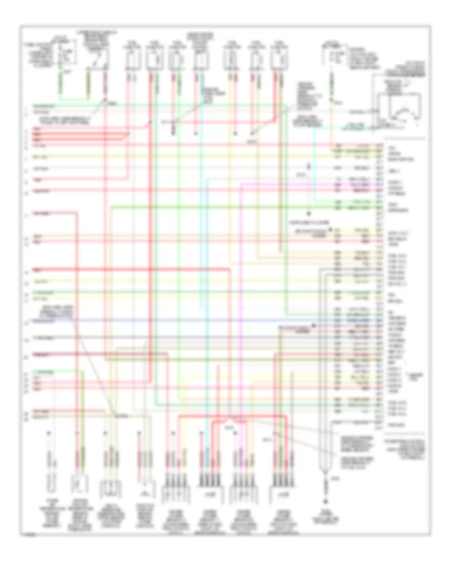
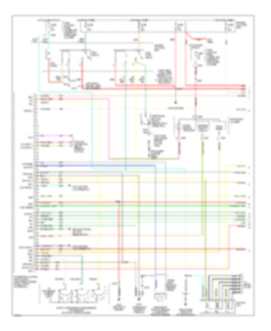
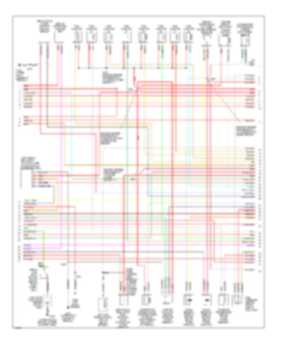
3.0L 12-Valve, Engine Performance Wiring Diagrams (2 of 3) for Ford Taurus LX 1999
List of elements for 3.0L 12-Valve, Engine Performance Wiring Diagrams (2 of 3) for Ford Taurus LX 1999:
- (behind transmission fill tube) power steering pressure switch
- (below spare wheelwell) canister vent
- (between cylinder heads) camshaft position (cmp) sensor
- (dash harn, near breakout to g104 at left front fender)
- (eng harn, at breakout to turbine shaft speed sensor)
- (eng harn, near breakout to ho2s 21) red s148
- (engine harn, near breakout to ckp sensor) s104
- (on rear side of transaxle) turbine shaft speed sensor
- Ax4s/ax4n transaxle
- Eam air pump (left front of vehicle, rear of bumper)
- Eam solid state relay (left front of vehicle, rear of bumper)
- Egr vacuum regulator (evr) solenoid valve (on front of intake manifold)
- Electronic pressure control solenoid
- Evap canister purge solenoid (right rear of eng compt, on firewall)
- Fuel pressure sensor (under car, on the front side of fuel tank)
- G123 (upper right center of firewall)
- Mass air flow sensor (near eng air intake assembly)
- Nca
- Red
- Red/pnk
- S101
- S106
- S107 (engine harn, near breakout to ckp sensor)
- S134
- S149 (engine harness, near breakout to heated oxygen sensor 21)
- S158
- Shift solenoid #1
- Shift solenoid #2
- Shift solenoid #3
- Solenoid
- Thermactor air bypass solenoid (above exhaust manifold, left rear of engine)
- Torque converter clutch solenoid
- Transmission fluid temper- ature sensor
- Vehicle speed sensor (vss) (rear center of eng compt, on transaxle)
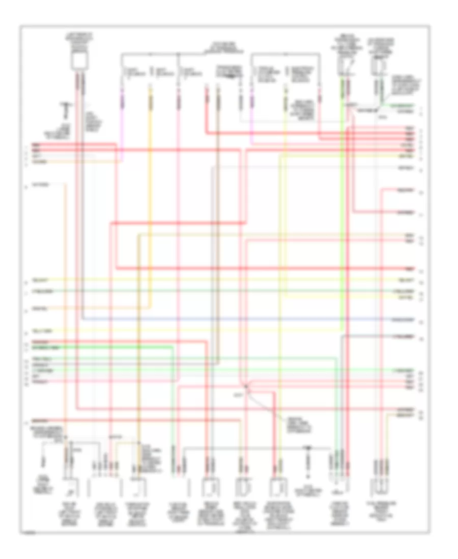
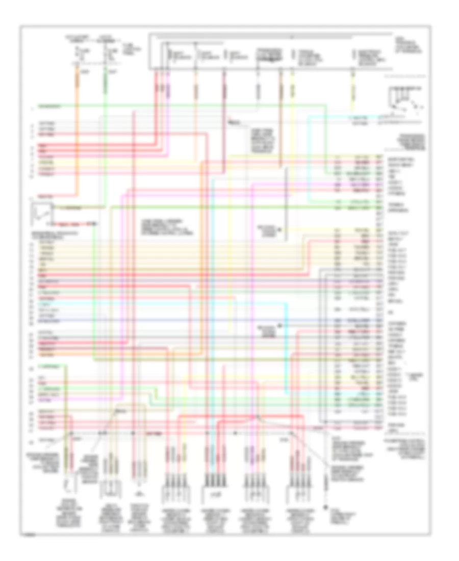
3.0L 12-Valve, Engine Performance Wiring Diagrams (3 of 3) for Ford Taurus LX 1999
List of elements for 3.0L 12-Valve, Engine Performance Wiring Diagrams (3 of 3) for Ford Taurus LX 1999:
- heated oxygen sensor 21 (front of eng compt, on exhst manifold)
- (eng harn, near breakout to ckp sensor)
- (eng harn, near breakout to eng oil press switch)
- (engine harn, near fuel inj 5)
- (engine harness, near breakout to engine oil pressure switch)
- (engine harness, near breakout to fuel inj 6)
- (engine harness, near breakout to turbine shaft speed sensor)
- (front center of eng compt, behind battery)
- (main harn, near breakout to g200 at left kick panel)
- (on top of trans housing) digital transmission (dtr) range sensor
- (rear center of eng compt) idle air control valve
- (upper front side of brake pedal) brake pedal position (bpp) switch
- A/c pres
- Ac rly out
- Air conditioning system
- Battery junction box
- Bpp
- C247
- Cmp sens
- Delta pressure feedback egr (dpfe) sensor (on intake manifold)
- Dpfe sens
- Eam relay
- Engine coolant temperature sensor (rear of engine block, near thermostat)
- Epc sol
- Evap canp sol
- Fpm
- From dtr sensor (diagram 1 of 3)
- Ftp sens
- Fuel inj 1
- Fuel inj 2
- Fuel inj 3
- Fuel inj 4
- Fuel inj 5
- Fuel inj 6
- Fuel injector
- Fuse 15a
- Fuse junction panel (under left corner of instrument cluster)
- G123 (upper right center of firewall)
- Heated oxygen sensor 11 (rear of eng compt, on exhst manifold)
- Heated oxygen sensor 12 (downstream from cataltic conv 1)
- Heated oxygen sensor 22 (downstream from cataltic conv 2)
- Heater ctrl
- Ho2s 11
- Ho2s 12
- Ho2s 21
- Ho2s 22
- Hot at all times
- Iac
- Ign coil c
- Instrument cluster
- Intake air temperature sensor (on air intake assembly)
- Kapwr
- Maf sens
- Nca
- Ohms
- Powertrain control module (pcm) (right rear corner of eng compt, on firewall)
- Pwr gnd
- Red
- Red/pnk
- Ref volt
- S100
- S102
- S103
- S104
- S106
- S110
- S111
- S144
- S308
- Sig rtn
- Tan
- Tcc
- Throttle position sensor (behind intake manifold)
- Tp sens
- Tr3a
- Tss sens
- Vpwr
- Vss (+)
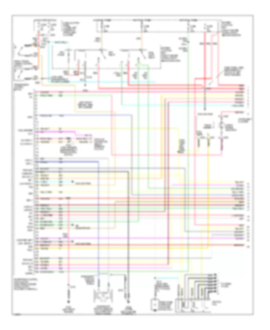
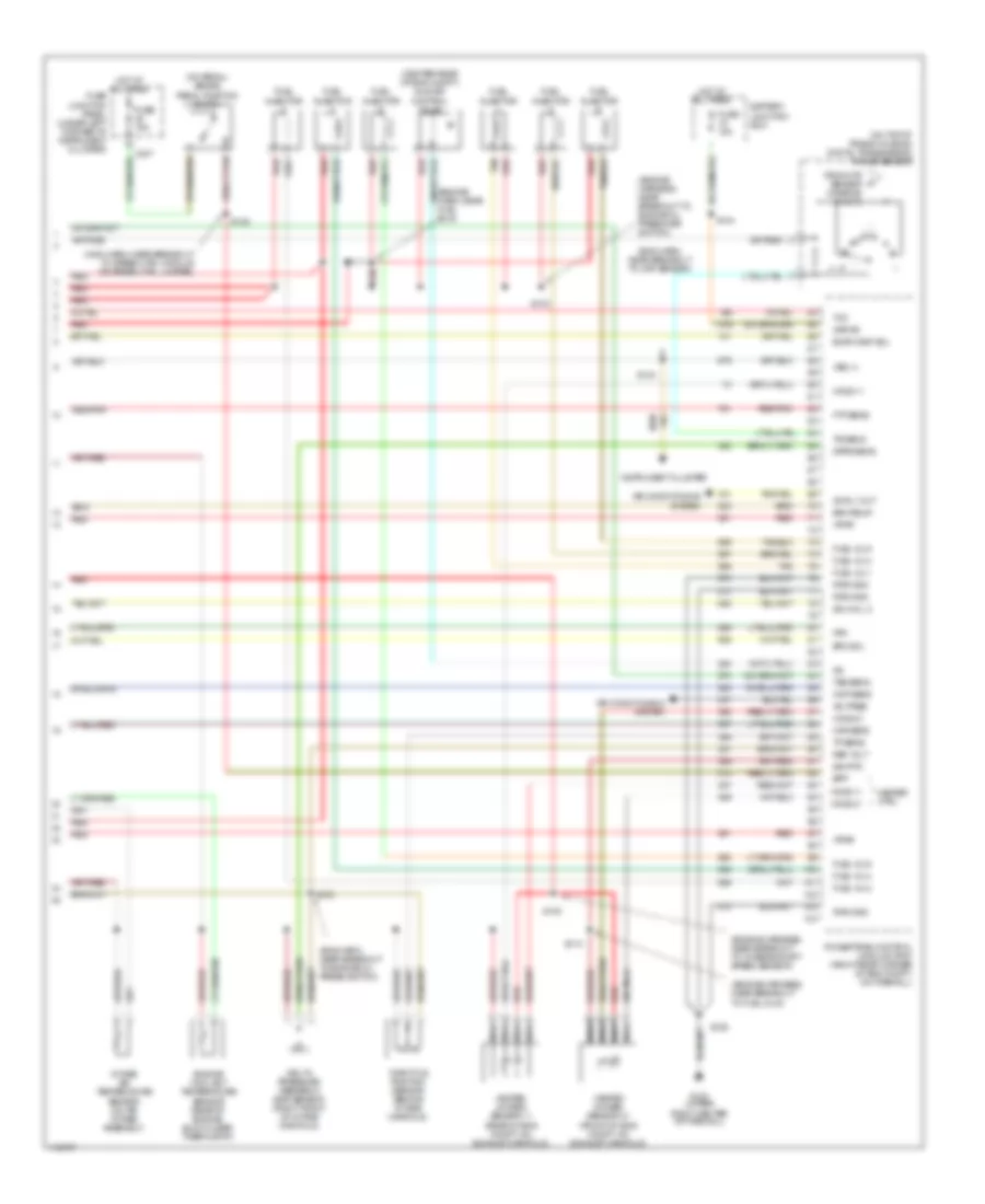
3.0L 24-Valve, Engine Performance Wiring Diagrams (1 of 3) for Ford Taurus LX 1999
List of elements for 3.0L 24-Valve, Engine Performance Wiring Diagrams (1 of 3) for Ford Taurus LX 1999:
- (dash panel harn, near breakout to g104 at left front fender)
- (front center of eng compt, behind radiator)
- (left front fender, near air cleaner)
- (main harn, left side dash) s232
- (main harn, near breakout to inst cluster)
- Accs
- Air conditioning
- Battery junction box
- C225
- C235
- C250
- Canister vent
- Case gnd
- Check engine indicator
- Ckp (+)
- Ckp (-)
- Cooling fans
- Crankshaft position sensor (on lower right front of eng)
- Crankshaft position sensor shield
- Data link connector (below steering column)
- Dlc
- Dlc bus (+)
- Dlc bus (-)
- Ect
- Evr
- Fpm
- Fuel level
- Fuel pump relay
- Fuel sender
- Fuse 10a
- Fuse 15a
- Fuse 20a
- Fuse 30a
- Fuse 5a
- Fuse junction panel (under left corner of instrument cluster)
- G100 (left front fender)
- G104
- G123 (upper right center of firewall)
- High spd rly
- Ho2s 12
- Hot at all times
- Hot in start or run
- Iat
- Ign coil a
- Ign coil b
- Ignition coil
- Imrc
- Instrument cluster
- Kapwr
- Low fan rly
- Maf rtn
- Mil
- Nca
- Pcm diode
- Pcm relay
- Powertrain control module (pcm) (right rear corner of eng compt, mounted in firewall)
- Prndl/trans- mission control switch
- Psp
- Pwr gnd
- Radio noise capacitor (mounted on ign coil)
- Red
- S105
- S108
- S112 (eng harn, near break- out to ho2s 11)
- S120
- S122
- S133
- S135
- S144
- S218 (main harness, near breakout trans control switch)
- S219
- S220
- Ss 1
- Ss 2
- Ss 3
- Tach
- Tacho- meter
- Tcc
- Tcs
- Tft
- To spark plugs
- Transmission control switch
- Vss (-)
3.0L 24-Valve, Engine Performance Wiring Diagrams (2 of 3) for Ford Taurus LX 1999
List of elements for 3.0L 24-Valve, Engine Performance Wiring Diagrams (2 of 3) for Ford Taurus LX 1999:
- (behind transmission fill tube) power steering pressure switch
- (below spare wheelwell) canister vent solenoid
- (engine harness, near breakout to engine coolant temperature sender)
- (engine harness, near breakout to heated oxygen sensor 11)
- (engine harness, near breakout to turbine shaft speed sensor)
- (left front of engine, below valve cover) camshaft position sensor
- (on rear side of transaxle) turbine shaft speed sensor
- (rear center of eng compt) idle air control valve
- Egr vacuum regulator (evr) solenoid valve (mounted on front of intake manifold)
- Evap canister purge solenoid (right rear of eng compt, mounted on firewall)
- Fuel injector
- Fuel pressure sensor (on front side of fuel tank)
- Fuel pump/ fuel gauge sender (on front side of fuel tank)
- G100 (left front fender)
- G123 (upper right center of firewall)
- G405 (lower middle section of rear quarter panel)
- Inertia fuel shut- off (ifs) switch (behind right rear wheelwell)
- Intake air temperature sensor (on air intake assembly)
- Intake manifold runner control (imrc) (on left side of engine mounted on valve cover)
- Knock sensor (left rear of eng, below intake manifold)
- Mass air flow sensor (in eng air intake assembly)
- Red
- Red/pnk
- S106
- S147
- S150
- S152
- Tan
- Vehicle speed sensor (vss) (rear center of eng compt, on transaxle)
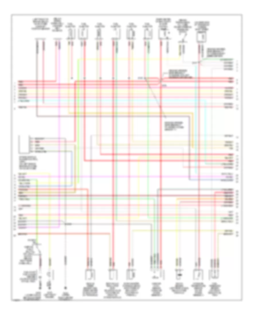
3.0L 24-Valve, Engine Performance Wiring Diagrams (3 of 3) for Ford Taurus LX 1999
List of elements for 3.0L 24-Valve, Engine Performance Wiring Diagrams (3 of 3) for Ford Taurus LX 1999:
- (dash panel harn, near breakout to g104 at left front fender)
- (engine harness, near breakout evap canister purge solenoid)
- (engine harness, near breakout to campshaft position sensor)
- (engine harness, near breakout to engine coolant temperature sender)
- (engine harness, near breakout to ho2s 11)
- (engine harness, near breakout to throttle position sensor)
- (front of brake pedal)
- (main harness, near breakout to g200 at left kick panel)
- A/c pres
- Ac rly out
- Air condi- tioning system
- Air conditioning system
- Ax4n transaxle
- Bpp
- Brake pedal position (bpp) switch
- C235
- C247
- Cmp sens
- D/2
- Delta pressure feedback egr sensor (right front of intake manifold)
- Dpfe sens
- Electronic pressure control (epc) solenoid
- Engine coolant temperature sensor (on rear of engine, near thermostat)
- Epc sol
- Evap canp sol
- Fpm
- Ftp sens
- Fuel inj 1
- Fuel inj 2
- Fuel inj 3
- Fuel inj 4
- Fuel inj 5
- Fuel inj 6
- Fuse 15a
- Fuse 5a
- Fuse junction panel (under left corner of instrument cluster)
- G123 (upper right center of firewall)
- Heated oxygen sensor 11 (rear of eng compt, on exhaust manifold)
- Heated oxygen sensor 12 (under vehicle, downstream, from catalytic converter 1)
- Heated oxygen sensor 21 (front of eng compt, on exhaust manifold)
- Heated oxygen sensor 22 (under vehicle, downstream, from catalytic converter 2)
- Heater ctrl
- Ho2s 11
- Ho2s 12
- Ho2s 21
- Ho2s 22
- Hot at all times
- Hot in start or run
- Iac
- Ign coil c
- Instrument cluster system
- Knock sens
- Maf sens
- Nca
- Powertrain control module (pcm) (right rear corner of eng compt, mounted in firewall)
- Pwr gnd
- Red
- Red/pnk
- Ref volt
- S102
- S104
- S106
- S134
- S151
- S153
- S157
- S224
- S308
- Shift solenoid
- Sig rtn
- Tan
- Tcil
- Throttle position sensor (center rear of eng)
- Torque converter clutch (tcc) solenoid
- Tp sens
- Tr sens
- Transmission fluid temper- ature sensor
- Transmission range sensor (on rear side of transaxle)
- Tss sens
- Vpwr
- Vss (+)
3.0L Flex Fuel, Engine Performance Wiring Diagrams (1 of 3) for Ford Taurus LX 1999
List of elements for 3.0L Flex Fuel, Engine Performance Wiring Diagrams (1 of 3) for Ford Taurus LX 1999:
- (dash panel harn, near breakout to 42-pin conn in left side of eng compt)
- (left front fender, near air cleaner)
- (not used)
- (upper right center of firewall)
- Accs
- Air conditioning (a/c high press switch)
- Battery junction box
- C225
- C235
- C250
- C251
- Check engine indicator
- Ckp feed
- Ckp rtn
- Connector (below steering column)
- Cooling fans
- Cooling fans (high speed rly)
- Cooling fans (low speed rly)
- Crankshaft position sensor (lower right front of engine)
- Data link
- Digital transmission range sensor (dtr sensor) (on top of trans housing)
- Distance to empty module
- Dlc
- Dlc bus (+)
- Dlc bus (-)
- Dte
- Eam rly
- Ect
- Evr
- Fpm
- Fuel pump relay
- Fuel pump/ fuel gauge sender (in fuel tank)
- Fuel sense
- Fuse 15a
- Fuse 20a
- Fuse 30a
- Fuse 5a
- Fuse junction panel (under left corner of instrument cluster)
- G100 (left front fender)
- G104
- G123
- Gnd
- High fan rly
- Hot at all times
- Hot in start or run
- Iat
- Ign coil a
- Ign coil b
- Ignition coil
- Inertia fuel shutoff switch (behind right wheelwell)
- Instrument cluster
- Low fan rly
- Maf rtn
- Mil
- Nca
- Pcm diode
- Pcm relay
- Powertrain control module (pcm) (right rear corner of eng compt, on firewall)
- Psp
- Pwr gnd
- Quarter panel) g405
- R n
- Radio noise capacitor (on ignition coil)
- Red
- S105
- S106
- S108
- S112
- S120
- S133
- S135
- S224
- Ss 1
- Ss 2
- Ss 3
- Tach
- Tacho- meter
- Tft
- To dtr sensor (diagram 3 of 3)
- To spark plugs
- Tr1
- Tr2
- Tr4
3.0L Flex Fuel, Engine Performance Wiring Diagrams (2 of 3) for Ford Taurus LX 1999
List of elements for 3.0L Flex Fuel, Engine Performance Wiring Diagrams (2 of 3) for Ford Taurus LX 1999:
- (behind transmission fill tube) power steering pressure switch
- (dash harn, near breakout to 42-pin conn in left side of eng compt)
- (engine harn, near breakout to ckp sensor)
- (engine harness, near breakout to ckp sensor) s104
- (left rear of engine block) camshaft position sensor
- (on rear side of transaxle) turbine shaft speed sensor
- (top center of transaxle) ax4s/ax4n transaxle
- Cam- shaft position sensor shield
- Eam air pump (left front of vehicle, rear of bumper)
- Eam solid state relay (left front of vehicle, rear of bumper)
- Egr vacuum regulator (evr) valve solenoid (on front of intake manifold)
- Electronic pressure control solenoid
- Eng harn, at breakout to turbine shaft speed sensor)
- Evaporative emission (evap) canister purge solenoid (right rear of eng compt, on firewall)
- Flex fuel sensor (right rear of engine compt)
- Fuel pressure sensor (front side of fuel tank)
- G123 (right center of firewall)
- G123 (upper right center of firewall)
- Mass air flow (maf) sensor (near air intake assembly)
- Red
- Red/pnk
- S101
- S106
- S107
- S108
- S134
- S148
- S149 (eng harn, near breakout to heated oxygen sensor 21)
- S158
- Shift solenoid
- Thermactor air bypass solenoid (above exhaust manifold)
- Torque converter clutch solenoid
- Transmission fluid temper- ature sensor
- Vehicle speed sensor (vss) (rear center of eng compt, on transaxle)
3.0L Flex Fuel, Engine Performance Wiring Diagrams (3 of 3) for Ford Taurus LX 1999
List of elements for 3.0L Flex Fuel, Engine Performance Wiring Diagrams (3 of 3) for Ford Taurus LX 1999:
- heated oxygen sensor 21 (front of eng compt, on exhaust manifold)
- (center rear of eng compt) idle air control valve
- (eng harn, near breakout to ckp sensor)
- (eng harn, near breakout to engine oil press switch)
- (engine harn, near fuel inj 5)
- (engine harness, near breakout to engine oil pressure switch)
- (engine harness, near breakout to fuel inj 6)
- (engine harness, near breakout to turbine shaft speed sensor)
- (main harn, near breakout to speed ctrl module or speed ctrl jumper)
- (on pedal) brake pedal position switch
- (on top of trans housing) digital transmission range sensor
- A/c pres
- Ac rly out
- Air conditioning system
- Battery junction box
- Bpp
- C247
- Cmp sens
- Delta pressure feedback egr sensor (right front of intake manifold)
- Dpfe sens
- Eam relay
- Engine coolant temperature sensor (rear of engine block, near thermostat)
- Epc sol
- Evap canp sol
- Fpm
- From dtr sensor (diagram 1 of 3)
- Ftp sens
- Fuel inj 1
- Fuel inj 2
- Fuel inj 3
- Fuel inj 4
- Fuel inj 5
- Fuel inj 6
- Fuel injector
- Fuse 15a
- Fuse junction panel (under left corner of instrument cluster)
- G123 (upper right center of firewall)
- Heated oxygen sensor 11 (rear of eng compt, on exhaust manifold)
- Heater ctrl
- Ho2s 11
- Ho2s 21
- Hot at all times
- Iac
- Ign coil c
- Instrument cluster
- Intake air temperature sensor (on air intake assembly)
- Kapwr
- Maf sens
- Nca
- Powertrain control module (pcm) (right rear corner of eng compt, on firewall)
- Pwr gnd
- Red
- Red/pnk
- Ref volt
- S100
- S102
- S103
- S104
- S106
- S110
- S111
- S138
- S144
- Sig rtn
- Tan
- Tcc
- Throttle position sensor (behind intake manifold)
- Tp sens
- Tr sens
- Tss sens
- Vpwr
- Vss (+)
3.4L
3.4L SHO, Engine Performance Wiring Diagrams (1 of 3) for Ford Taurus LX 1999
List of elements for 3.4L SHO, Engine Performance Wiring Diagrams (1 of 3) for Ford Taurus LX 1999:
- (dash panel harness, near breakout to 42-pin black conn in left side of engine above transaxle)
- (engine harness, near breakout to evaporative emission canister valve)
- (engine harness, near breakout to heated oxygen sensor 21)
- (left front fender, near air cleaner)
- (upper right center of firewall)
- Accs
- Air condi- tioning system
- Battery junction box
- C225
- C250
- Canister vent
- Ccp 5
- Ccp 6
- Ccp 7
- Check engine indicator
- Ckp feed
- Ckp rtn
- Coil per plug
- Cooling fans
- Cooling fans system
- Cpp 1
- Cpp 3
- Crankshaft position sensor (left front of engine)
- Crankshaft position sensor shield
- Data link connector (below steering column)
- Dlc
- Dlc bus (+)
- Dlc bus (-)
- Eam air pump (left front vehicle, rear of bumper)
- Eam rly
- Eam solid state relay (left front of vehicle, rear of bumper)
- Ect
- Engine compartment
- Evr
- Fpm
- Fuel pump relay
- Fuel sender
- Fuse 15a
- Fuse 20a
- Fuse 30a
- Fuse junction panel
- Fuse/relay box
- G104
- G123
- G123 (upper right center of firewall)
- Gnd
- High spd rly
- Ho2s 12
- Hot at all times
- Hot in start or run
- Iat
- Imrc
- Instrument cluster
- Instrument cluster system
- Kapwr
- Knock sens 2
- Low spd rly
- Maf rtn
- Mil
- Nca
- Pcm diode
- Pcm relay
- Powertrain control module (pcm) (right rear corner of eng compt, on firewall)
- Psp
- Pwr gnd
- Radio noise capacitor 1 (top of engine above imrc)
- Radio noise capacitor 2 (top of engine, near 4 coil)
- Red
- S106
- S108
- S122
- S133
- S135
- S144
- S149
- S156
- S161
- S162
- S163
- S218 (main harn, near breakout to passive anti-theft system)
- S219
- S447
- Ss 1
- Ss 2
- Ss 3
- Tach
- Tacho- meter
- Tcc
- Tcil
- Tcs
- Tft
- Thermactor air bypass solenoid (right side of engine, above manifold)
- Transmissions system
3.4L SHO, Engine Performance Wiring Diagrams (2 of 3) for Ford Taurus LX 1999
List of elements for 3.4L SHO, Engine Performance Wiring Diagrams (2 of 3) for Ford Taurus LX 1999:
- (behind transmission fill tube) power steering pressure switch
- (below spare tire) canister vent
- (below valve cover) camshaft position sensor
- (center rear of eng compt) idle air control valve
- (dash panel harness, near breakout to speed control module or speed control jumper)
- (engine harness, near breakout to engine coolant temperature sender)
- (engine harness, near breakout to heated oxygen sensor 11)
- (engine harness, near breakout to turbine shaft speed sensor)
- (left side of eng compt, on valve cover) intake manifold runner control
- (lower middle section of rear quarter panel)
- (on rear side of transaxle) turbine shaft speed sensor
- Anti-lock brake control module (below battery)
- Egr vacuum regulator (evr) solenoid valve (on front of intake manifold)
- Evaporative emission (evap) canister purge solenoid (right rear of eng compt, on firewall)
- Fuel injector
- Fuel pressure sensor (front side of fuel tank)
- Fuel pump/ fuel gauge sender (in fuel tank)
- G100 (left front fender)
- G123 (upper right center of firewall)
- G405
- Inertia fuel shut- off (ifs) switch (behind right wheel- well)
- Intake air temperature sensor (on air intake assembly)
- Knock sensor 1 (rear of engine, below intake manifold)
- Knock sensor 2 (rear of engine, below intake manifold)
- Mass air flow (maf) sensor (in eng air intake assembly)
- Red
- Red/pnk
- S106
- S107
- S108
- S120
- S142
- S147
- S150
- S152 (engine harness, near breakout to heated oxygen sensor 11)
- Tan
- Tan/red
- Vss out
3.4L SHO, Engine Performance Wiring Diagrams (3 of 3) for Ford Taurus LX 1999
List of elements for 3.4L SHO, Engine Performance Wiring Diagrams (3 of 3) for Ford Taurus LX 1999:
- (dash panel harn, near breakout to 42-pin black conn above transaxle)
- (dash panel harness, near breakout to speed control module or speed control jumper)
- (engine harness, near breakout to campshaft position sensor)
- (engine harness, near breakout to engine coolant temp sender)
- (engine harness, near breakout to throttle position sensor)
- A/c pres
- Ac rly out
- Air condi- tioning system
- Ax4n transaxle (top center of transaxle)
- Boo
- Brake pedal pos switch (on brake pedal)
- C235
- C247
- Cmp sens
- Cpp 2
- Cpp 4
- Cpp 8
- Delta pressure feedback egr sensor (right front of intake manifold)
- Dpfe sens
- Eam rly
- Electronic pressure control (epc) solenoid
- Engine coolant temperature sensor (rear of eng block, near thermostat)
- Epc sol
- Evap canp sol
- Fpm
- Ftp sens
- Fuel inj 1
- Fuel inj 2
- Fuel inj 3
- Fuel inj 4
- Fuel inj 5
- Fuel inj 6
- Fuel inj 7
- Fuel inj 8
- Fuse 15a
- Fuse 5a
- Fuse junction panel
- G123 (upper right center of firewall)
- Heated oxygen sensor 11 (rear of eng compt, on exhaust manifold)
- Heated oxygen sensor 12 (under vehicle, downstream from catalytic converter 1)
- Heated oxygen sensor 21 (front of eng compt, on exhaust manifold)
- Heated oxygen sensor 22 (under car body, downstream from catalytic converter 2)
- Heater ctrl
- Ho2s 11
- Ho2s 12
- Ho2s 21
- Ho2s 22
- Hot at all times
- Hot in start or run
- Iac
- Knock sens 1
- Maf sens
- Nca
- Powertrain control module (pcm) (right rear corner of eng compt, on firewall)
- Pwr gnd
- Red
- Red/pnk
- Ref volt
- S102
- S106
- S134
- S138
- S151
- S153
- S157 (engine harness, near breakout to 10-pin white conn centered atop of transaxle)
- Shift solenoid
- Sig rtn
- Tan
- Tan/red
- Throttle position sensor (rear of eng, behind intake manifold)
- Torque converter clutch (tcc) solenoid
- Tp sens
- Tr sens
- Transmission fluid temper- ature sensor
- Transmission range sensor (rear side of transaxle)
- Tss
- Vpwr
- Vss (+)