ENGINE PERFORMANCE
3.9L
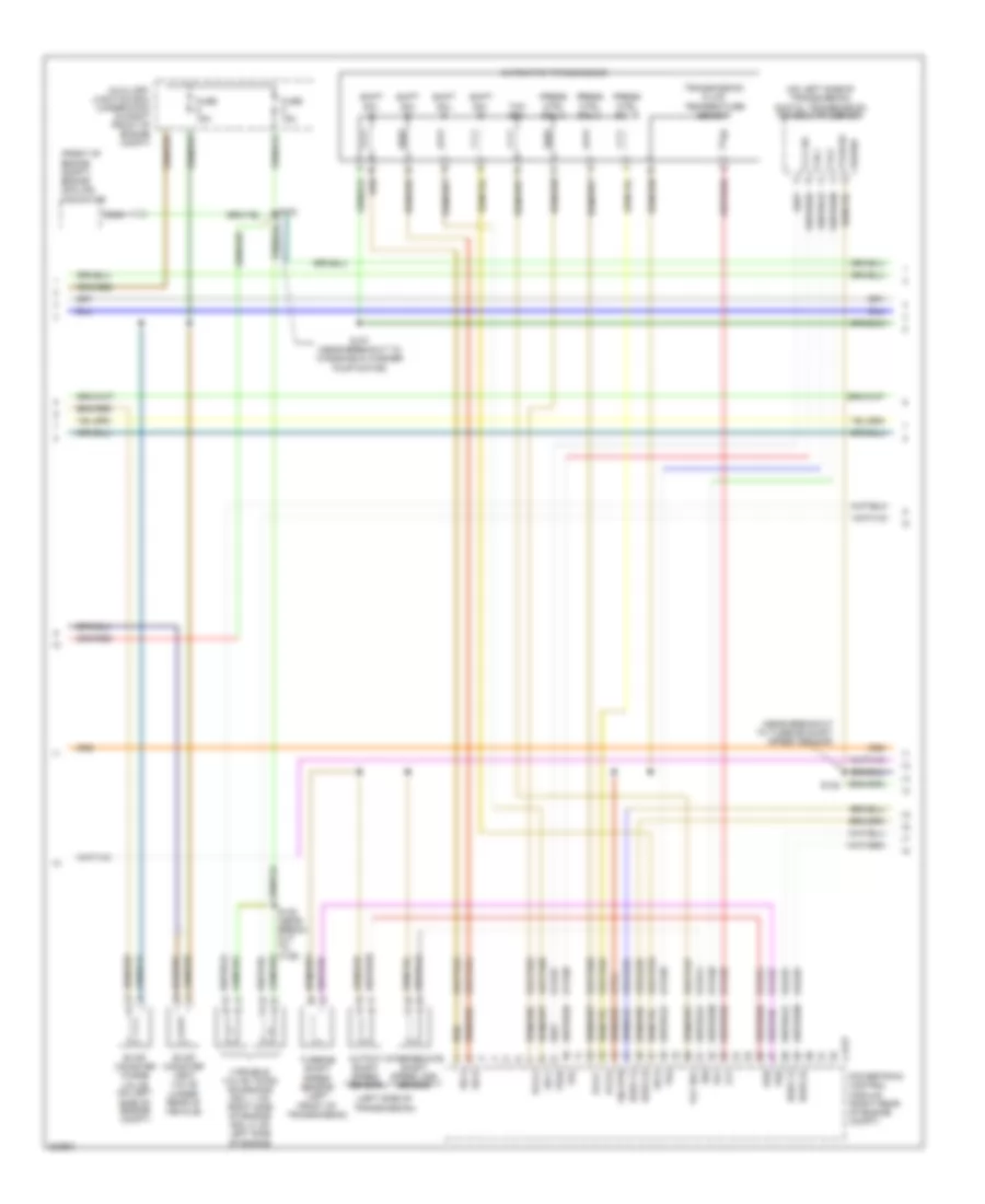
3.9L, Engine Performance Wiring Diagram (1 of 4) for Ford Thunderbird 2005

List of elements for 3.9L, Engine Performance Wiring Diagram (1 of 4) for Ford Thunderbird 2005:
- (at right front fender) g103
- (in breakout to underhood auxiliary junction box)
- (in luggage compt, near battery) battery junction box
- (near breakout to c264)
- (near breakout to g103)
- (near breakout to outside temp sensor)
- (near breakout to right side of engine compt)
- (near breakout to subwoofer amplifier) s413
- (right side of engine compt) g102
- 15s-re21
- 15s-re8
- 29-re8
- 29s-pg1
- 29s-re13
- 31-re21
- 31-re25
- 31-re26
- 31-re8
- 31s-pg24
- 4-ec7
- 4-re8
- 5-ec7
- 5-re8
- 7-pg24
- 7-pg29
- 7-pg30
- 7-re14
- 7-re8
- 8-fa88
- 8-ja56
- 8-pa47
- 8-pg28
- 8-pg29
- 8-pg30
- 8-re32
- 8-rj13
- 8-rj22
- 8-rj40
- 8-ta21
- 8-ta67
- 8-ta68
- 9-pg30
- 9-re8
- 9-rj22
- 91-re27
- 91s-fa79
- 91s-rl25
- 91s-rl3
- A/c pressure transducer sensor (on lower left front of engine compt)
- Ac clutch
- Ac press
- Air conditioning system
- Brake in
- Brake pressure switch (on top of brake pedal support)
- C175b
- C270b
- C270d
- C270e
- Can +
- Can -
- Central junction box (behind right kick panel)
- Cooling fans system
- Cops & heated oxygen sensor relay
- Cruise control system
- Data link connector (under left side of dash)
- Electronic throttle control module (behind left center of dash)
- Etc ref
- Etc sig
- Etc sig rtn
- Etc signal
- Evap ctrl
- Evap purge
- Fan ctrl
- Fuel pump motor diode
- Fuel tank pressure transducer sensor (under rear of vehicle)
- Fuse 40a
- Fuse 5a
- Ground
- Hot at all times
- Hot in run or start
- Iat sens
- Inertia fuel shutoff (ifs) switch (inside left kick panel)
- Maf rtn
- Maf sig
- Man mode (+)
- Man mode (-)
- Mass air flow (maf) sensor (on air intake assembly, on left front of engine compt)
- Mt sw +
- Mt sw -
- O/d cancel sw
- Od off
- Pcm power diode
- Pcm power relay
- Power
- Powertrain control module (pcm) (right rear of engine compt)
- Prg sig
- Ref volt
- Rem sig
- Rest mod
- S101
- S104
- S109
- S113
- S114
- S218
- S221
- Scp +
- Scp -
- Signal rtn
- Spd sw
- Tank press
- Transmission shift selector (a/t)
- Underhood auxiliary junction box (in right front of engine compt)
- Voltage
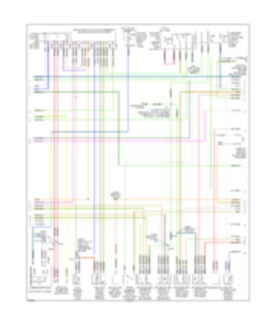
3.9L, Engine Performance Wiring Diagram (2 of 4) for Ford Thunderbird 2005
List of elements for 3.9L, Engine Performance Wiring Diagram (2 of 4) for Ford Thunderbird 2005:
- (front of engine compt) engine cooling fan motor
- (left side of transmission)
- (near breakout to turbine shaft speed sensor)
- (on left side of transmission) digital transmission range (dtr) sensor
- (under rear of vehicle)
- 8-rj25
- 8-rj26
- 8-ta26
- 8-ta27
- 8-ta37
- 8-ta38
- 8-ta39
- 8-ta40
- 8-ta51
- 8-ta74
- 9-ta1
- 91s-rj25
- 91s-rj26
- 91s-ta23
- 91s-ta24
- 91s-ta47
- 91s-ta63
- 91s-ta64
- 91s-ta65
- 91s-ta69
- 91s-ta70
- Automatic transmission
- Auxiliary junction box (underhood) (in right front of engine compt)
- C175t
- Evap canister purge valve (on left side of engine compt)
- Evap canister vent valve
- Fuse 15a
- H2os 12
- H2os 22
- Intermediate shaft speed (iss) sensor
- Iss
- Nca
- Oss
- Output shaft speed sensor
- P,2,1,3/4
- P,n,1
- P,r,2
- P,r,n,3/4
- Pcs a
- Pcs b
- Pcs c
- Power
- Powertrain control module (right rear of engine compt)
- Press ctrl sol a
- Press ctrl sol b
- Press ctrl sol c
- S102
- S107 (near breakout to windshield washer pump motor)
- S122
- S125 (near break- out to c139)
- Shift sol a
- Shift sol b
- Shift sol c
- Shift sol d
- Sig rtn
- Ss a
- Ss b
- Ss c
- Ss d
- Tcc sol
- Tft
- Tr1
- Tr2
- Tr3a
- Tr4
- Transmission fluid temperature sensor
- Tss
- Turbine shaft speed sensor (left front of transmission)
- Variable valve timing solenoids (sol 1: on right side of engine (sol 2: on left side of engine
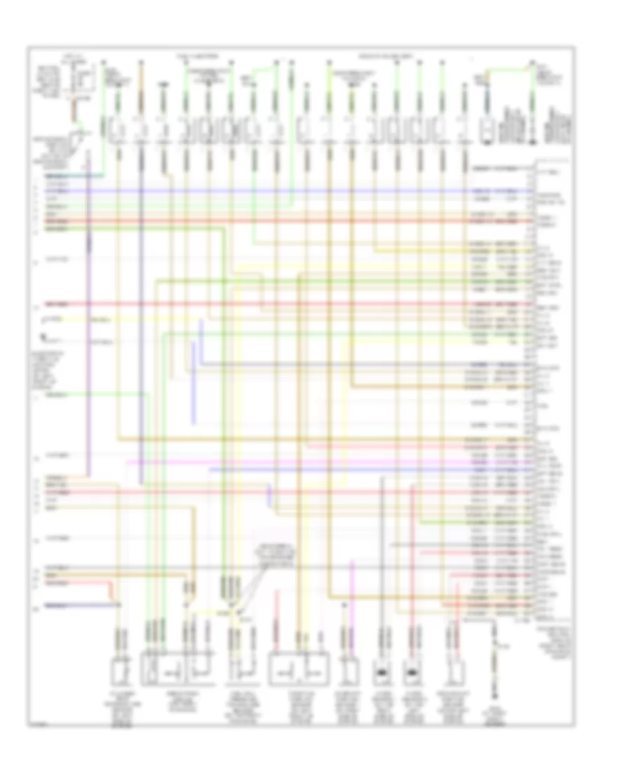
3.9L, Engine Performance Wiring Diagram (3 of 4) for Ford Thunderbird 2005
List of elements for 3.9L, Engine Performance Wiring Diagram (3 of 4) for Ford Thunderbird 2005:
- (behind seats, on vehicle crossbeam) rear electronic module (rem)
- (near breakout to c139)
- (near breakout to defrost mode actuator)
- (near breakout to fuel tank pressure transducer sensor)
- (near breakout to g103) s100
- (near breakout to ho2s 22)
- 15-rp12b
- 15s-dk32
- 15s-rg2a
- 29s-cf58
- 29s-dk30
- 31s-rg2a
- 4-eg12a
- 5-eg12a
- 8-ga25
- 8-ga7
- 8-re32
- 9-ga1
- Abs control module (right front of engine compt)
- Air conditioning system
- Battery junction box (in luggage compt, near battery)
- C220b
- C270a
- C283b
- C283c
- C283d
- C420b
- C420c
- C420e
- C420f
- Camshaft position sensor 2 (on left side of engine)
- Central junction box (cjb) (behind right kick panel)
- Check engine ind
- Data link connector (under left side of dash)
- Engine oil temperature sensor (lower left front of engine)
- Fuel pump driver module (under rear of vehicle)
- Fuel pump relay
- Fuel rail temperature sensor (on right rear of engine)
- Fuel sender (under vehicle, in fuel tank)
- Fuse 10a
- Fuse 15a
- Fuse 5a
- G401 (right side of luggage compt)
- Generator
- Heated oxygen sensor 11 (near lower right rear of engine)
- Heated oxygen sensor 12 (in exhaust, rear of catalytic converter)
- Heated oxygen sensor 21 (near lower left rear of engine)
- Heated oxygen sensor 22 (in exhaust, rear of catalytic converter)
- Hot at all times
- Hot in start or run
- Instrument cluster
- Interior auxiliary junction box (under left side of dash)
- Microprocessor
- Nca
- Power steering pressure switch (on left side of engine compt)
- S111 (in dash panel to headlamp junction harness, in breakout to underhood auxiliary junction box)
- S123
- S132
- S206
- S207
- S414
- Scp +
- Scp -
- Underhood auxiliary junction box (in right front of engine compt)
- Vpwr
3.9L, Engine Performance Wiring Diagram (4 of 4) for Ford Thunderbird 2005
List of elements for 3.9L, Engine Performance Wiring Diagram (4 of 4) for Ford Thunderbird 2005:
- (near break- out to ignition transformer capacitor 2)
- (near breakout to cop 8) s129
- (near breakout to fuel injector 8)
- 10-ba25
- 10-rj18
- 10-rj19
- 10-rj4
- 32-rg3
- 33-rg3
- 7-rj28
- 7-rn11
- 8-ba25
- 8-ce6
- 8-rj11
- 8-rj12
- 8-rj14
- 8-rj15
- 8-rj18
- 8-rj19
- 8-rj2
- 8-rj20
- 8-rj26
- 8-rj28
- 8-rj3
- 8-rj33
- 8-rj39
- 8-rj4
- 8-rj7
- 8-rl26
- 8-rl27
- 9-re1
- 9-rj28
- 91s-rj14
- 91s-rj15
- 91s-rl10
- 91s-rl11
- 91s-rl12
- 91s-rl13
- 91s-rl14
- 91s-rl15
- 91s-rl16
- 91s-rl17
- 91s-rl7
- 91s-rr10
- 91s-rr11
- 91s-rr12
- 91s-rr5
- 91s-rr6
- 91s-rr7
- 91s-rr8
- 91s-rr9
- Brake pedal position switch (on top of brake pedal support)
- C175e
- C270b
- Camshaft position sensor 1 (on right side of engine)
- Capacitor 1 transformer
- Capacitor 2 (in left rear
- Central junction box (cjb) (behind right kick panel)
- Ckp +
- Ckp -
- Cmp1 sens
- Cmp2 sens
- Coil 1
- Coil 2
- Coil 3
- Coil 4
- Coil 5
- Coil 6
- Coil 7
- Coil 8
- Coils on plugs (cop)
- Crankshaft position sensor (lower left side of engine)
- Cyl temp
- Cylinder head temperature sensor (on left side of engine)
- Dc volt
- Egr system module (top front of engine)
- Electronic throttle control motor (on left front of engine)
- Eot sig
- Ept ctrl
- Ept sens
- Ept sig
- Etc mtr
- Fuel injectors
- Fuel rail
- Fuel rail pressure transducer sensor (on top front of engine)
- Fuse 5a
- G103 (at right front fender)
- Gen
- Gen com
- Ho2s 11
- Ho2s 21
- Hot at all times
- Ignition
- Inj 1
- Inj 2
- Inj 3
- Inj 4
- Inj 5
- Inj 6
- Inj 7
- Inj 8
- Knock sensor 1 (on top right side of engine)
- Knock sensor 2 (on top left side of engine)
- Ks 1 feed
- Ks 1 rtn
- Ks 2 feed
- Ks 2 rtn
- Nca
- Of engine)
- Of engine) (left rear
- Powertrain control module (right rear of engine compt)
- Psp sw fd
- Ref volt
- Return
- S124
- S126
- S127
- S130
- S131 (near breakout to cop 4)
- S150 (near breakout to cmp 1)
- Temp sig
- Throttle position sensor (on left front of engine)
- Tps
- Tps rtn
- Tps sig
- Transformer ignition
- Vvt sol1
- Vvt sol2