ENGINE PERFORMANCE
3.0L
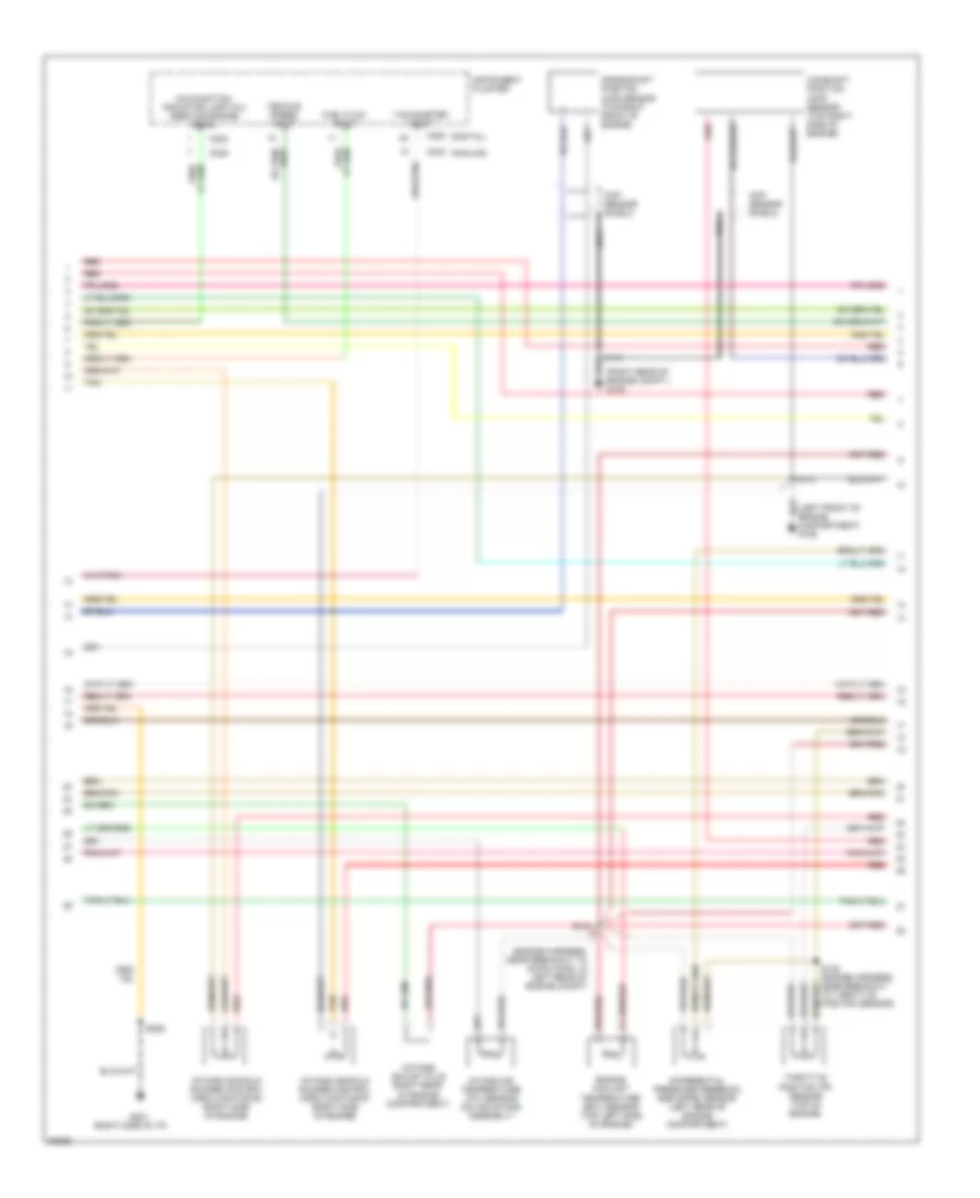
3.0L, Engine Performance Wiring Diagrams (1 of 4) for Ford Windstar LX 1997

List of elements for 3.0L, Engine Performance Wiring Diagrams (1 of 4) for Ford Windstar LX 1997:
- (dash panel harness, near breakout to engine compt fuse box)
- (dash panel harness, near breakout to g106 ground at left front of engine compt)
- (engine harness, near breakout to octane adjust plug)
- (left front of engine compartment) constant control relay module (ccrm)
- (right rear of engine compt)
- A/c sig
- Air conditioning system
- Case gnd
- Ckp (+)
- Ckp (-)
- Coil c1
- Coil c2
- Coil c3
- Constant control relay module (ccrm) (left front of engine compartment)
- Cooling fans
- Cooling fans system
- Data link (+)
- Data link (-)
- Data link connector (dlc) (below i/p, right of steering column)
- Dlc (pwr sply)
- Ect sens in
- Egr vac reg
- Engine compartment fuse box (left side of engine comartment)
- Engine compartment fuse box (left side of engine compartment)
- Fuel flow out
- Fuel pump mon
- Fuel pump relay
- Fuse 25a
- Fuse n 20a
- Fuse r 15a
- Fuse s 30a
- Fuse v 10a
- G105
- G106 (left front of engine compartment)
- High fan ctrl
- Ho2s sig #3
- Hot at all times
- Hot in start or run
- I/p fuse panel (behind left side of i/p)
- Iat sens
- Icm shield
- Idm
- Ign gnd
- Ign pwr
- Ignition coil (upper left rear of engine)
- Ignition control module (icm) (right rear of engine compartment)
- Maf sig rtn
- Mil
- Nca
- Octane adj plug
- Off
- Pcm power relay
- Pip
- Pnk
- Powertrain control module (pcm) (behind right side of i/p)
- Primary
- Pwr gnd
- Radio interference capacitor (top right side of engine)
- Red
- S108
- S109
- S111
- S114
- S116
- S117
- S118
- S119
- S136
- Secondary
- Shd gnd
- Shift sol 1
- Shift sol 2
- Spout
- To spark plugs
- Trans ctrl sw
- Trans fl temp
- Transmission control indicator lamp (tcil)
- Transmission control switch (tcs)
- Vss (-)
3.0L, Engine Performance Wiring Diagrams (2 of 4) for Ford Windstar LX 1997
List of elements for 3.0L, Engine Performance Wiring Diagrams (2 of 4) for Ford Windstar LX 1997:
- (analog)
- (digital)
- (engine harness, near breakout to 42-pin conn in left rear of engine compt)
- (engine harness, near breakout to octane adjust plug)
- (engine harness, near breakout to throttle position sensor)
- (left front of engine compartment)
- C200
- C202
- C239
- C240
- Camshaft position (cmp) sensor (left side of engine)
- Cmp shield
- Crankshaft position (ckp) sensor (lower right side of engine)
- Crankshaft position (ckp) sensor shield
- Differential pressure feedback egr (dpfe) sensor (right rear of engine)
- Engine coolant temperature (ect) sensor (upper left side of engine)
- Fuel flow input
- G106
- G201 (right side of i/p)
- Instrument cluster
- Intake air temperature (iat) sensor (left side of engine compartment)
- Malfunction indicator lamp (mil) (service engine soon)
- Nca
- Octane adjust plug (right rear of engine compartment)
- Pnk
- Red
- S101
- S113
- S124
- S125
- S138
- Shield
- Spark output (spout) check connector (right rear corner of engine compartment)
- Tachometer input
- Throttle position (tp) sensor (upper rear of engine)
- Vehicle speed input
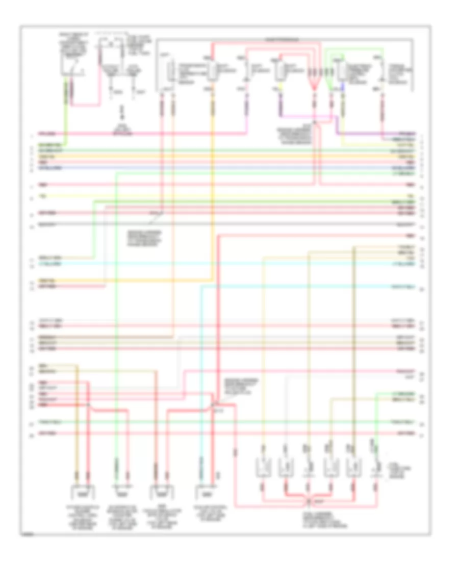
3.0L, Engine Performance Wiring Diagrams (3 of 4) for Ford Windstar LX 1997
List of elements for 3.0L, Engine Performance Wiring Diagrams (3 of 4) for Ford Windstar LX 1997:
- (engine harness, near breakout to octane adjust plug)
- (engine harness, near breakout to transmission range sensor)
- (fuel harness, near breakout to 8-pin gray conn in left side of engine)
- (left side of engine compartment) ax4s transaxle
- (on left "b" pillar)
- (right rear of cargo compartment) inertia fuel shut-off (ifs) switch
- Egr vacuum regulator (evr) solenoid valve (left rear of engine)
- Electronic pressure control (epc) solenoid
- Evaporative emission (evap) canister purge valve (center rear of engine compartment)
- Fuel injectors (top of engine)
- Fuel pump/ fuel gauge sender (top of fuel tank)
- G308
- Idle air control (iac) valve (upper left rear of engine)
- Pnk
- Red
- S115
- S120
- S127
- S302
- S407
- Shift solenoid
- Tan
- Torque converter clutch (tcc) solenoid
- Transmission fluid temperature (tft) sensor
- With trailer tow
- Without trailer tow
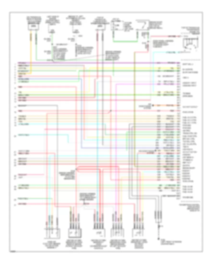
3.0L, Engine Performance Wiring Diagrams (4 of 4) for Ford Windstar LX 1997
List of elements for 3.0L, Engine Performance Wiring Diagrams (4 of 4) for Ford Windstar LX 1997:
- (behind i/p, left of steering column)
- (engine harness, near breakout to 42-pin conn in left rear of engine compt)
- (engine harness, near breakout to oxygen sensor #22)
- (engine harness, near breakout to turbine shaft speed sensor)
- (left side of engine compartment) speed control servo
- (on top of brake pedal)
- (on transaxle, rear of engine)
- (top of transaxle)
- A/c cut out sw
- A/c wot cutout
- Air conditioning system
- B+ (kapwr)
- Brake on/off
- Brake on/off (boo) switch
- C234
- Cam pos sens
- Cooling fans system
- Dpfe sens
- Epc sol ctrl
- Evap can purge
- Fuel inj #2
- Fuel inj #4
- Fuel inj #6
- Fuel inj 1 ctrl
- Fuel inj 3 ctrl
- Fuel inj 5 ctrl
- Fuel pump ctrl
- Fuse 15a
- G106 (left front of engine compartment)
- Generic electronic module (gem)
- Heated oxygen sensor #11 (ho2s) (on front exhaust)
- Heated oxygen sensor #12 (ho2s) (on rear exhaust)
- Heated oxygen sensor #21 (ho2s) (rear of engine on exhaust pipe)
- Heated oxygen sensor #22 (ho2s) (rear of engine, on exhaust pipe)
- Ho2s #11
- Ho2s #11 sig
- Ho2s #12
- Ho2s #21
- Ho2s #21 sig
- Ho2s #22
- Ho2s #22 sig
- Hot at all times
- I/p fuse panel (behind left side of i/p)
- Iac valve ctrl
- Icm shield
- Low cool fan
- Maf sens
- Mass air flow (maf) sensor (on air intake assembly)
- Nca
- Near breakout to engine compt fuse box)
- Power gnd
- Powertrain control module (pcm) (behind right side of i/p)
- Pwr (vpwr)
- Pwr gnd
- Red
- Red/
- Ref volt
- S112
- S113
- S114
- S121
- S122 (engine harness, near breakout to brake fluid level switch)
- S123
- S126
- S237 (main harness, near breakout to 3-pin conn at left side of i/p, taped to harness)
- Shift sol 3
- Sig rtn
- Tan
- Tcc sol ctrl
- Tp sens
- Tr sens
- Trans ctrl ind
- Transmission range (tr) sensor
- Tss
- Turbine shaft speed (tss) sensor
- Vehicle speed sensor (vss)
- Vss (+)
- Vss input
3.8L
3.8L, Engine Performance Wiring Diagrams (1 of 4) for Ford Windstar LX 1997
List of elements for 3.8L, Engine Performance Wiring Diagrams (1 of 4) for Ford Windstar LX 1997:
- (dash panel harness, near breakout to engine compt fuse box)
- (dash panel harness, near breakout to g106 ground at left front of engine compt)
- (left front of engine compartment) constant control relay module (ccrm)
- (left front of engine compartment) g106
- (right rear of engine compartment) g105
- A/c sig
- Air conditioning system
- Case gnd
- Ckp out (+)
- Ckp out (-)
- Constant control relay module (ccrm) (left front of engine compartment)
- Cooling fans
- Cooling fans system
- Data link (+)
- Data link (-)
- Data link connector (dlc) (below i/p, right of steering column)
- Dlc (pwr sply)
- Ect sens in
- Egr vac reg
- Engine compartment fuse box (left side of engine compartment)
- Fuel flow out
- Fuel pump mon
- Fuel pump relay
- Fuse 25a
- Fuse n 20a
- Fuse r 15a
- Fuse s 30a
- Fuse v 10a
- G106 (left front of engine compartment)
- High spd fan
- Ho2s sig #12
- Hot at all times
- Hot in start or run
- I/p fuse panel (behind left side of i/p)
- Iat sens
- Idm
- Ign prim
- Ignition coil (top right side of engine)
- Imrc cont
- Imrc mon #1
- Imrc mon #2
- Low spd fan
- Maf sig rtn
- Mil
- Nca
- Octane adjust
- Off
- Pcm power relay
- Powertrain control module (pcm) (behind right side of i/p)
- Primary
- Pwr gnd
- Radio interference capacitor (top right side of engine)
- Red
- S101
- S108
- S109
- S111
- S112
- S116
- S119
- S136
- S143 (dash panel harness, near breakout to brake fluid level switch)
- S144
- Secondary
- Shift sol 1
- Shift sol 2
- Tan
- To spark plugs
- Trans ctrl sw
- Trans fl temp
- Transmission control indicator lamp (tcil)
- Transmission control switch (tcs)
- Vss (-)
3.8L, Engine Performance Wiring Diagrams (2 of 4) for Ford Windstar LX 1997
List of elements for 3.8L, Engine Performance Wiring Diagrams (2 of 4) for Ford Windstar LX 1997:
- (analog)
- (digital)
- (engine harness, near breakout to 42-pin conn, in left rear of engine compt)
- (left front of engine compartment) g106
- (right rear of engine compt.) g105
- (right side of i/p)
- C200
- C202
- C239
- C240
- Camshaft position (cmp) sensor (top right side of engine)
- Ckp sensor shield
- Cmp sensor shield
- Crankshaft position (ckp) sensor (top right front of engine)
- Differential pressure feedback egr (dpfe) sensor (left rear of engine compartment)
- Engine coolant temperature (ect) sensor (top left side of engine)
- Fuel flow input
- G201
- Instrument cluster
- Intake air temperature (iat) sensor (on air intake assembly)
- Intake manifold runner control (imrc) monitor #1 (right side of engine)
- Intake manifold runner control (imrc) monitor #2 (right side of engine)
- Malfunction indicator lamp (mil) (service engine soon)
- Nca
- Octane adjust plug (right rear of engine compartment)
- Red
- S112
- S119
- S124
- S138 (engine harness, near breakout to throttle position sensor)
- S206
- Tachometer input
- Tan
- Throttle position (tp) sensor (top of engine)
- Vehicle speed input
3.8L, Engine Performance Wiring Diagrams (3 of 4) for Ford Windstar LX 1997
List of elements for 3.8L, Engine Performance Wiring Diagrams (3 of 4) for Ford Windstar LX 1997:
- (engine harness, near breakout to octane adjust plug)
- (engine harness, near breakout to transmission range sensor)
- (fuel harness, near breakout to 8-pin gray conn, in left side of engine)
- (right rear of cargo compartment) inertia fuel shut-off (ifs) switch
- Ax4s transaxle
- Egr vacuum regulator (evr) solenoid valve (top left rear of engine)
- Electronic pressure control (epc) solenoid
- Evaporative emission (evap) canister purge valve (top left side of engine)
- Fuel injectors (top of engine)
- Fuel pump/ fuel gauge sender (top of fuel tank)
- G308 (on left "b" pillar)
- Idle air control (iac) valve (top left side of engine)
- Intake manifold runner control (imrc) solenoid (center rear of engine)
- Pnk
- Red
- S115
- S120 (engine harness, near breakout to transmission range sensor)
- S127
- S141
- S302
- S407
- Shift solenoid
- Tan
- Torque converter clutch (tcc) solenoid
- Transmission fluid temperature (tft) sensor
- With trailer tow
- Without trailer tow
3.8L, Engine Performance Wiring Diagrams (4 of 4) for Ford Windstar LX 1997
List of elements for 3.8L, Engine Performance Wiring Diagrams (4 of 4) for Ford Windstar LX 1997:
- (behind i/p, left of steering column) generic electronic module (gem)
- (dash panel harness, near breakout to engine compt fuse box)
- (engine harness, near breakout to 42-pin conn in left rear of engine compt)
- (engine harness, near breakout to turbine shaft speed sensor)
- (left side of engine compartment) speed control servo
- (on transaxle, rear of engine)
- (top of transaxle) transmission range (tr) sensor
- (top of transaxle) turbine shaft speed (tss) sensor
- A/c cut out sw
- A/c wot cutout
- Air conditioning system
- B+ (kapwr)
- Brake on/off
- Brake on/off (boo) switch (on top of brake pedal)
- C234
- Cam pos in
- Dpfe sens
- Epc sol ctrl
- Evap can purge
- Fuel inj #2
- Fuel inj #4
- Fuel inj #6
- Fuel inj 1 ctrl
- Fuel inj 3 ctrl
- Fuel inj 5 ctrl
- Fuel pump ctrl
- Fuse 15a
- G106 (left front of engine compartment)
- Heated oxygen sensor #11 (ho2s) (on rear exhaust manifold)
- Heated oxygen sensor #12 (ho2s) (rear of engine, on right exhaust pipe)
- Heated oxygen sensor #21 (ho2s) (on front exhaust manifold)
- Heated oxygen sensor #22 (ho2s) (behind engine, on left exhaust pipe)
- Ho2s #11
- Ho2s #11 input
- Ho2s #12
- Ho2s #21
- Ho2s #22
- Ho2s #22 input
- Hot at all times
- I/p fuse panel (behind left side of i/p)
- Iac valve ctrl
- Ign prim
- Maf sens in
- Mass air flow (maf) sensor (on air intake assembly)
- Nca
- Power gnd
- Powertrain control module (pcm) (behind right side of i/p)
- Pwr (vpwr)
- Pwr gnd
- Red
- Ref volt
- S121
- S122 (engine harness, near breakout to brake fluid level switch)
- S123
- S126 (engine harness, near breakout to oxygen sensor #22)
- S128
- Shift sol 3
- Sig rtn
- Tan
- Tcc sol ctrl
- To 3-pin conn at left side of i/p, taped to harness)
- Tp sens in
- Tr sens
- Trans ctrl ind
- Tss in
- Vehicle speed sensor (vss)
- Vss (+)
- Vss input