ENGINE PERFORMANCE
5.7L
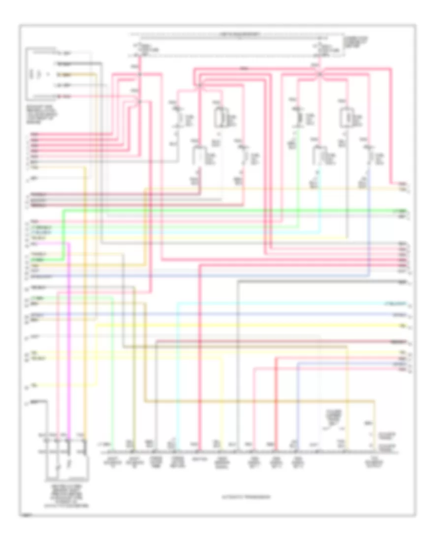
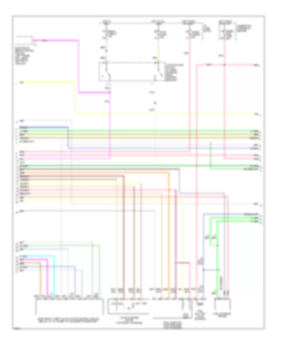
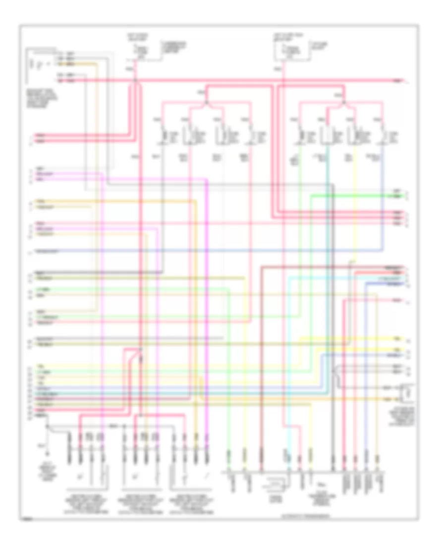
5.7L (VIN R), Engine Performance Wiring Diagrams (1 of 4) for GMC Vandura G3500 1996

List of elements for 5.7L (VIN R), Engine Performance Wiring Diagrams (1 of 4) for GMC Vandura G3500 1996:
- (lower front of engine, near crankshaft) crankshaft position sensor
- (right side of engine) evap canister purge solenoid valve
- (top left side of engine) idle air control valve motor
- A/c compressor clutch relay
- Camshaft position sensor (part of distributor, top rear of engine)
- Coil
- Coil "a" hi
- Coil "a" lo
- Coil "b" hi
- Coil "b" lo
- Egr sol output
- Fuel inj out no.1
- Fuel inj out no.2
- Fuel inj out no.3
- Fuel inj out no.4
- Fuel inj out no.5
- Fuel inj out no.6
- Fuel inj out no.7
- Fuel inj out no.8
- G117 (right rear of engine)
- Ground
- Heated oxygen sensor, left post-converter (in exhaust pipe in back of catalytic converter)
- Heated oxygen sensor, left pre-converter (in exhaust pipe in front of catalytic converter)
- Heated oxygen sensor, right post-converter (in exhaust pipe in back of catalytic converter)
- If equipped
- Ignition
- Knock sens signal
- Knock sensor (top rear of engine)
- Maf signal
- Map sens signal
- Nca
- Pnk
- Pnk c
- Position signal
- Return
- Sensor signal
- Shift sol a output
- Shift sol b output
- Shift solenoid output
- Signal
- Solenoid output
- Solid state
- Tan
- Tcc sol output
- Temp sens signal
- Underhood fuse-relay center
- Vehicle control module (engine compartment, left fender)
- Vehicle speed sensor (left side of transmission)
- Vss signal
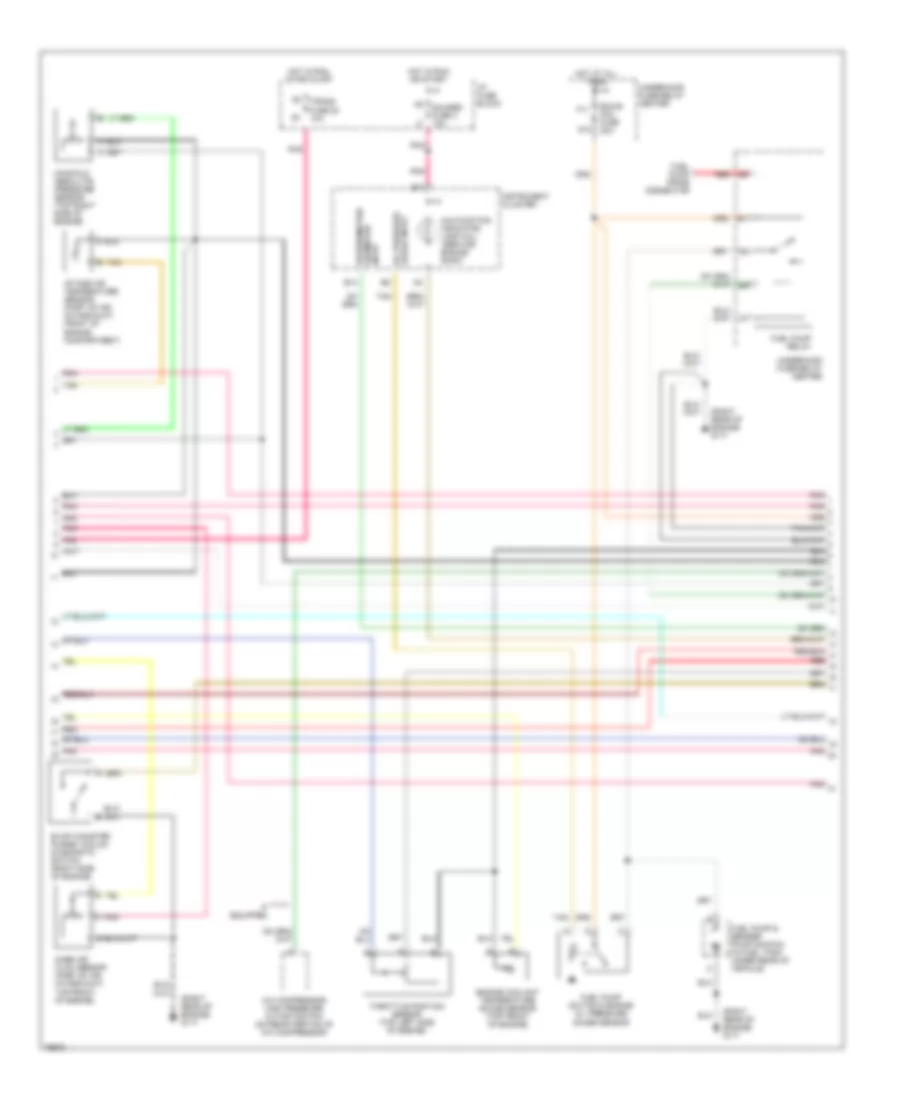
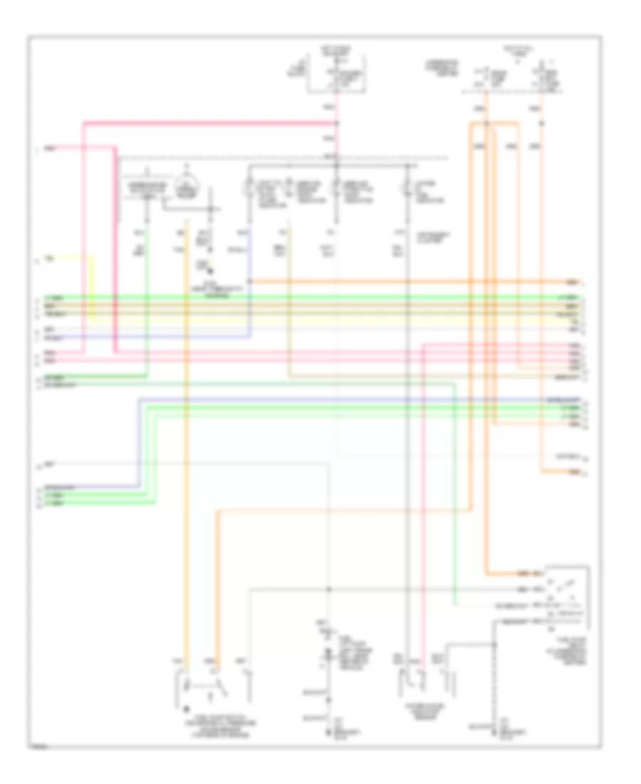
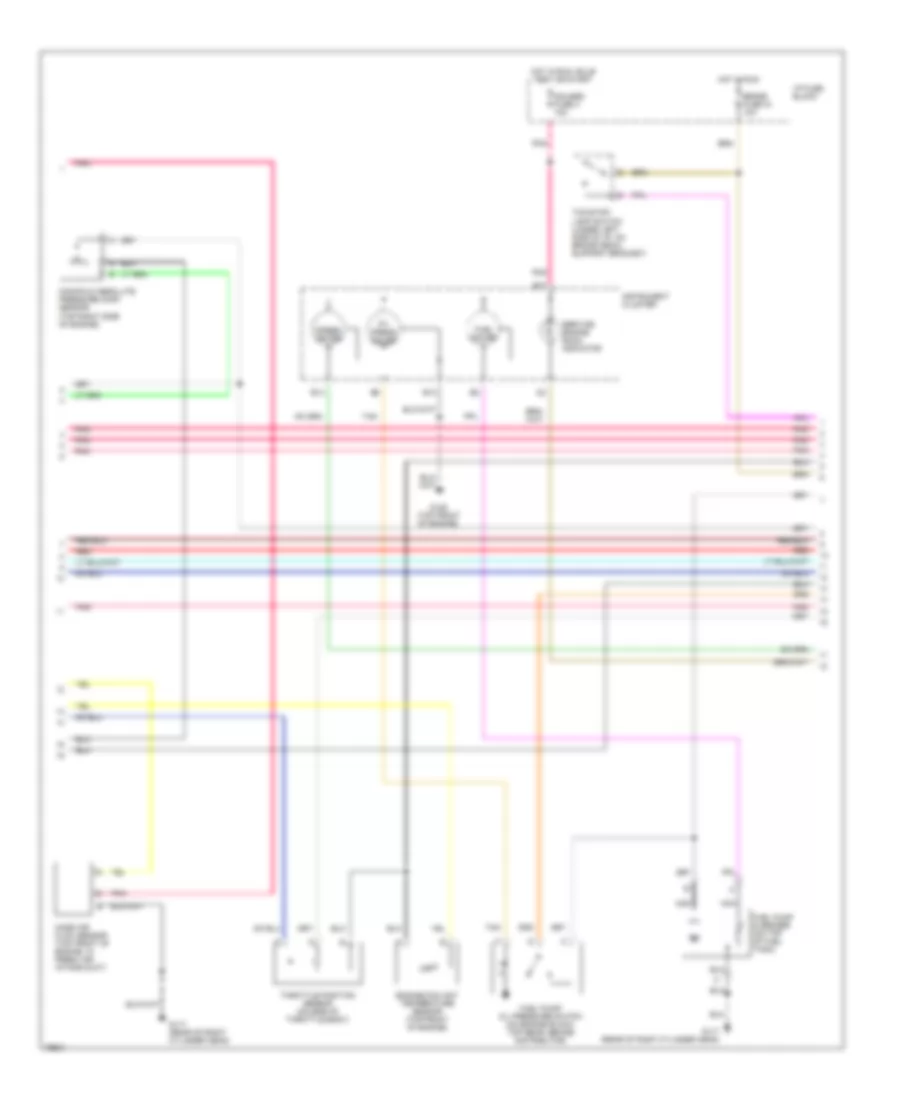
5.7L (VIN R), Engine Performance Wiring Diagrams (2 of 4) for GMC Vandura G3500 1996
List of elements for 5.7L (VIN R), Engine Performance Wiring Diagrams (2 of 4) for GMC Vandura G3500 1996:
- (w/4l60-e trans.)
- (w/4l80-e trans.)
- Automatic transmission
- Ecm-1 mini fuse 20a
- Exhaust gas recirculation valve solenoid (top front of engine)
- Force motor feed
- Force motor return
- Fuel inj. no.1
- Fuel inj. no.2
- Fuel inj. no.3
- Fuel inj. no.4
- Fuel inj. no.5
- Fuel inj. no.6
- Fuel inj. no.7
- Fuel inj. no.8
- Heated oxygen sensor, right pre-converter (in exhaust pipe in front of catalytic converter)
- Hot in run or start
- Ignition
- K7 eng-1 mini fuse 20a l8
- Nca
- Pnk
- Pnk tan
- Pss signal bit 1
- Pss signal bit 2
- Pss signal bit 3
- Red
- Shift solenoid "a"
- Shift solenoid "b"
- Tan
- Tcc solenoid output
- Temp sensor signal
- Under hood fuse-relay center
- W/4l60e 4-speed trans. only
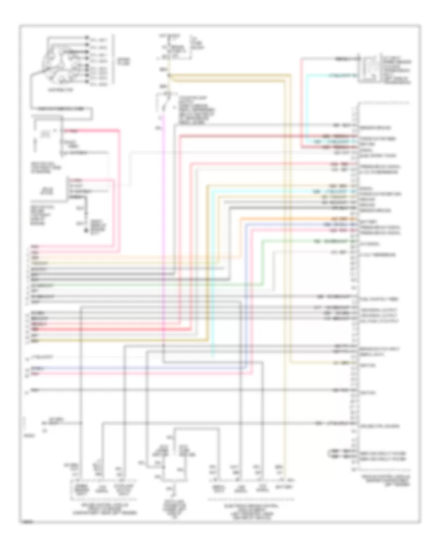
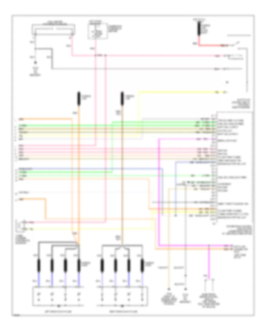
5.7L (VIN R), Engine Performance Wiring Diagrams (3 of 4) for GMC Vandura G3500 1996
List of elements for 5.7L (VIN R), Engine Performance Wiring Diagrams (3 of 4) for GMC Vandura G3500 1996:
- (right rear of engine) g117
- A/c compressor high pressure cutoff switch (on rear portion of a/c compressor)
- B14
- B17
- Ecm-b mini fuse 20a
- Engine coolant temperature gauge sensor (top front of engine)
- Evap canister purge vacuum diagnostic switch (right side of engine)
- F11
- Fuel pump & sender (pump shown) (in fuel tank under rear of vehicle)
- Fuel pump prime connector
- Fuel pump relay
- Fuel pump switch & engine oil pressure gauge sensor
- G12
- Gauges fuse 4 10a
- Hot at all times
- Hot in run or start
- Hot in run, start & off
- I/p fuse block
- If equipped
- Instrument cluster
- Intake air temperature sensor (part of air intake duct, front of engine compartment)
- Malfunction indicator lamp (mil) "service engine soon"
- Manifold absolute pressure sensor (top right side of engine)
- Mass air flow sensor (part of air intake duct, top front of engine)
- Oil pressure gauge input
- Pnk
- Pnk tan
- Red
- Speedometer/ odometer input
- Tan
- Tan b
- Throttle position sensor (top left side of engine)
- Trans fuse 20 10a
- Underhood fuse-relay center
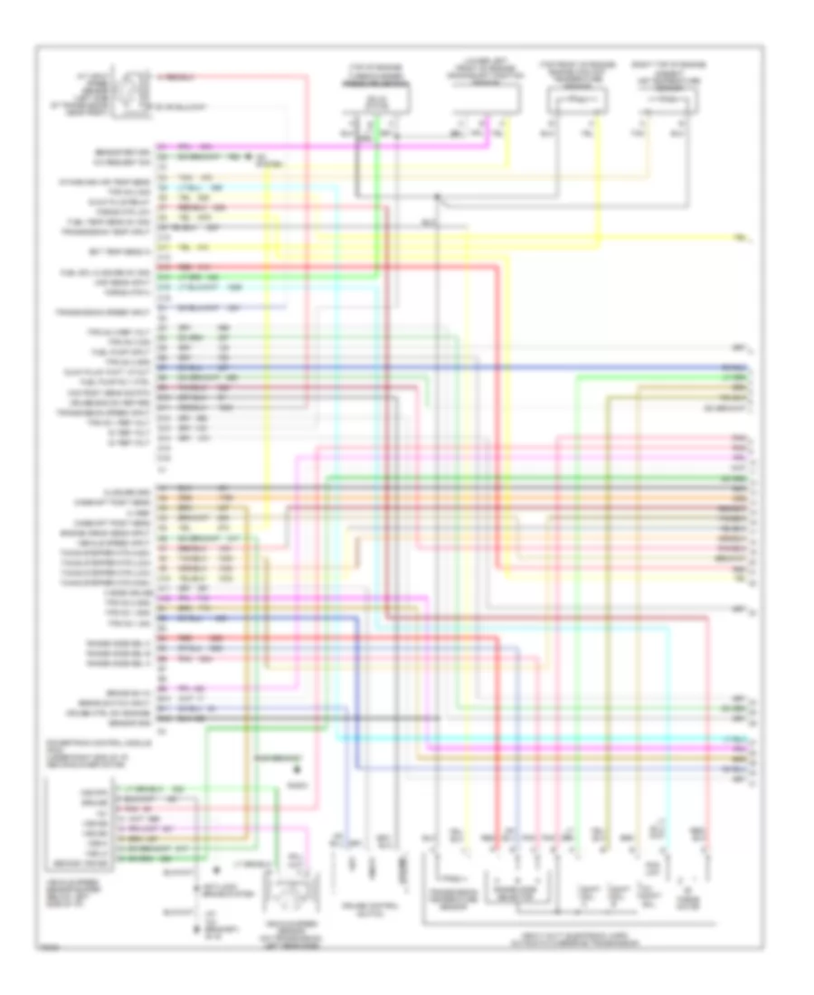
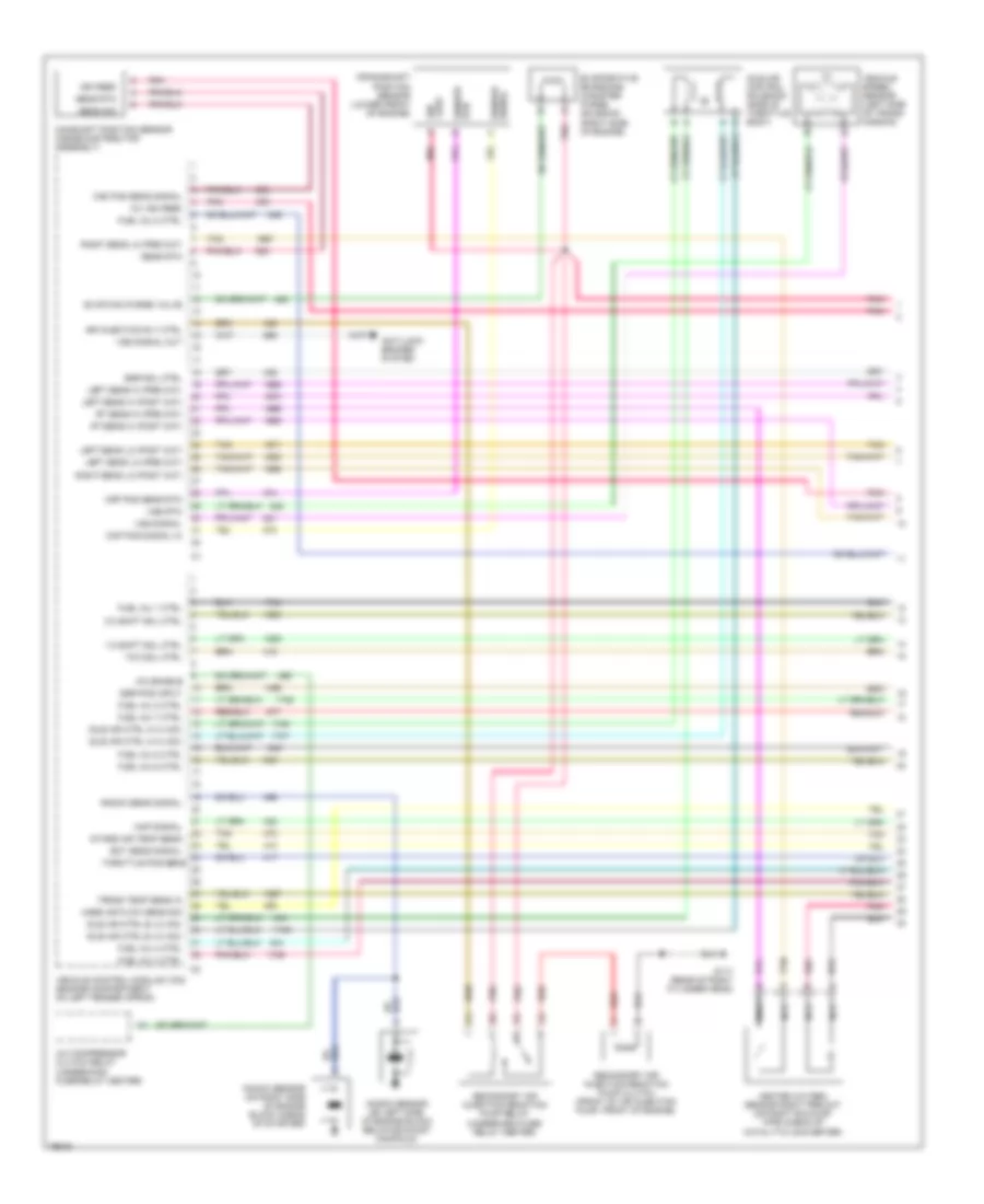
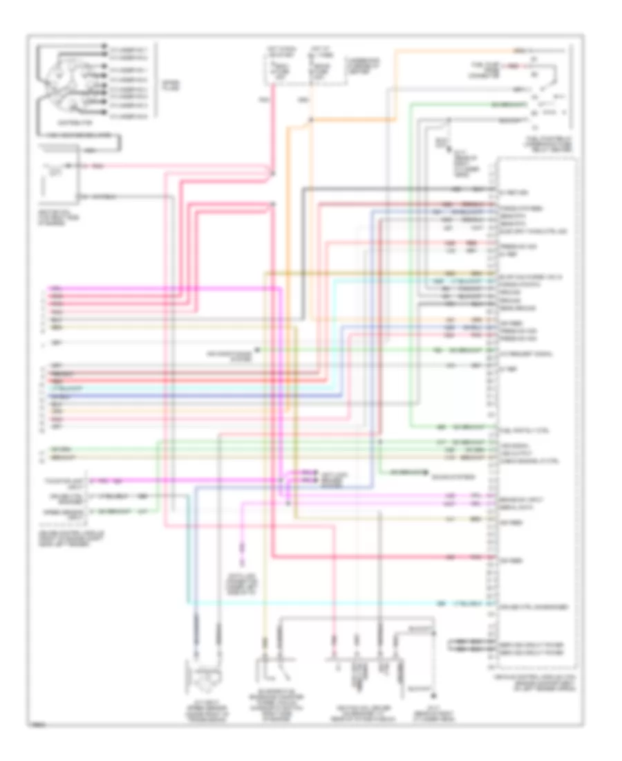
5.7L (VIN R), Engine Performance Wiring Diagrams (4 of 4) for GMC Vandura G3500 1996
List of elements for 5.7L (VIN R), Engine Performance Wiring Diagrams (4 of 4) for GMC Vandura G3500 1996:
- (right rear of engine) g117
- 5 volt reference
- 5 volts reference
- A/c signal
- A/t input speed sensor (w/4l80-e transmission only) (left side of transmission)
- B (not used)
- Battery
- Brake switch input
- Cruise control module (front of engine compartment near left fender)
- Cruise ctrl sig eng
- Cyl. no.1
- Cyl. no.2
- Cyl. no.3
- Cyl. no.4
- Cyl. no.5
- Cyl. no.6
- Cyl. no.7
- Cyl. no.8
- Data link connector (under left side of i/p)
- Distributor
- Elec spark timing
- Electronic brake control module (ebcm) (left frame rail near center of vehicle)
- Force motor feed
- Force motor return
- Fuel pump rly feed
- Ground
- Gvw over 8500 lbs.
- Gvw under 8500 lbs
- High voltage coil wire
- Hot in run
- I/p fuse block
- Ignition
- Ignition coil (top right side of engine)
- Ignition coil driver (top right side of engine)
- M4 brake fuse 18 10a n3
- Mal func lp output
- Pnk
- Pnk a
- Pressure sw signal
- Radio
- Red
- Return
- Sensor ground
- Serial data
- Service circuit power
- Signal
- Solid state
- Spark plugs
- Speed sensor input
- Stoplamp switch input
- Tcc signal
- Tcc/stoplamp switch (open w/brake pedal depressed) (below center of i/p, near brake pedal lever)
- Vcm signal
- Vehicle control module (engine compartment, left fender)
- Vss signal
- Vss signal output
6.5L
6.5L (VIN F), Engine Performance Wiring Diagrams (1 of 4) for GMC Vandura G3500 1996
List of elements for 6.5L (VIN F), Engine Performance Wiring Diagrams (1 of 4) for GMC Vandura G3500 1996:
- (at a/c bracket) g119
- (lower left front of engine) crankshaft position sensor
- (right top of engine)
- (top front of engine) engine coolant temperature sensor
- (top of engine)
- 12v
- 3/2 shift sol.
- 5 vref
- 5v ref volt
- A/c request sig
- A/c system
- A/t input speed sensor (left side of transmission near front)
- A10
- A11 3 mode cruise a12
- Ambient air temperature sensor
- Anti-lock brake system
- B10
- B11
- B12
- Brake sw in
- Brake switch input
- C10
- C11
- C12
- C13
- C14
- C15
- C16
- Cam posit sens sig rtn
- Camshaft posit sens
- Closure gnd
- Cruise control
- Cruise ctrl sw engage
- Cruise eng sw retard
- D10
- D11
- D12
- D13
- D14
- D15
- D16
- Ect temp sens in
- Engine crank sens input
- Force motor
- Force mtr hi
- Force mtr low
- Fuel pump input
- Fuel pump rly ctrl
- Fuel sol closure (5v sig)
- Fuel temp sens (5v sig)
- Glow plug "wait" lp out
- Glow plug relay
- Ground
- Heavy duty electronic 4-spd automatic overdrive transmission
- Intake man air temp sens
- Map sens input
- On/off
- Pcs low
- Pnk
- Powertrain control module (pcm) (under right end of i/p, above blower motor)
- Radio
- Range mode sel a
- Range mode sel b
- Range mode sel c
- Range mode selector
- Red
- Resume
- Second vss sig
- Sensor gnd
- Sensor return
- Set
- Shift sol. a
- Shift sol. b
- Solid state
- Switch
- Tan
- Timing stepper mtr (high)
- Timing stepper mtr (low)
- Tps no.1 gnd
- Tps no.1 ref volt
- Tps no.1 sig
- Tps no.2 gnd
- Tps no.2 sig
- Tps no.3 gnd
- Tps no.3 ref volt
- Tps no.3 sig
- Transmission speed input
- Transmission temp input
- Transmission temperature sensor
- Turbocharger pressure sensor
- Vehicle speed input
- Vehicle speed sensor (on transmission, left rear side)
- Vehicle speed sensor buffer (below left side of i/p)
- Vss hi
- Vss lo
- Vss rtn
- Vss sig
6.5L (VIN F), Engine Performance Wiring Diagrams (2 of 4) for GMC Vandura G3500 1996
List of elements for 6.5L (VIN F), Engine Performance Wiring Diagrams (2 of 4) for GMC Vandura G3500 1996:
- B6 stop fuse 1 25a c7
- D2 trans fuse 20 20a f1
- Diesel f5
- Electronic brake control module (left frame rail, near center of vehicle)
- Electronic throttle actuator control module (below i/p, attached to accelerator bracket)
- Fuel fuse 20a
- Fuel injection pump encoder (top of engine)
- Fuel shutoff valve solenoid
- Fuel solenoid driver
- Fuel temp.
- High
- Hot at all times
- Hot in run
- Hot in run or start
- I/p fuse block
- Low
- M4 brake fuse 18 10a n3
- Pnk
- Pnk pnk
- Red
- Tcc/stoplamp switch (at rear of brake pedal support bracket)
- Timing stepper motor (top front of engine)
- Underhood fuse-relay center
6.5L (VIN F), Engine Performance Wiring Diagrams (3 of 4) for GMC Vandura G3500 1996
List of elements for 6.5L (VIN F), Engine Performance Wiring Diagrams (3 of 4) for GMC Vandura G3500 1996:
- (at a/c bracket) g119
- (left frame rail, near center of vehicle)
- (near thermostat housing)
- A15
- B13
- B14
- B15
- B17
- Ecm-b fuse 20a
- Eng- bat fuse 15a
- F11
- Fuel lift pump
- Fuel pump relay (in underhood fuse-relay center)
- Fuel pump switch and engine oil pressure gauge sensor (top rear of engine)
- G12
- G125
- Gauges fuse 4 10a
- Hot at all times
- Hot in run or start
- I/p fuse block
- Instrument cluster
- Oil press gauge
- Pnk
- Service engine soon indicator
- Service throttle soon indicator
- Speedometer solid state logic
- Tan
- Underhood fuse-relay center
- Wait to start "glow plugs" indicator
- Water in fuel indicator
- Water in-fuel indicator sensor
6.5L (VIN F), Engine Performance Wiring Diagrams (4 of 4) for GMC Vandura G3500 1996
List of elements for 6.5L (VIN F), Engine Performance Wiring Diagrams (4 of 4) for GMC Vandura G3500 1996:
- "serv eng soon" ind
- "serv throttle soon" ind
- (dlc)
- (left side of i/p)
- 12v battery (fused)
- 12v battery fused
- 3/2 ctrl out
- A/c enable
- A/c system
- C10
- C11
- C12
- C13
- C14
- C15
- C16
- D10
- D11
- D12
- D13
- D14
- D15
- D16
- Data link connector
- Electronic brake control module (left frame rail, near center of vehicle)
- Eng-i k7
- Engine shutoff sol out
- Fuel heater (top rear of engine)
- Fuel sol module (5 vref)
- Fuel sol module feed
- Fuse 20a
- Fusible link
- Fusible link (12 ga. rust)
- Fusible links
- G119 (at a/c bracket)
- G125 (front of engine, near thermostat housing)
- Glow plug control relay (top right side of engine)
- Hot at all times
- Hot in run or start
- Ignition
- Left bank glow plugs
- Nca
- Pcm gnd
- Pnk
- Powertrain control module (pcm) (under right end of i/p, above blower motor)
- Red
- Right bank glow plugs
- Serial data sig
- Shift sol a input
- Shift sol b input
- Tps no.2 ref voltage
- Turbo charger wastegate solenoid
- Turbo chgr pwr vlv ctrl
- Underhood fuse-relay center
7.4L
7.4L (VIN J), Engine Performance Wiring Diagrams (1 of 4) for GMC Vandura G3500 1996
List of elements for 7.4L (VIN J), Engine Performance Wiring Diagrams (1 of 4) for GMC Vandura G3500 1996:
- 1-2 shift sol ctrl
- 12v ign feed
- 2-3 shift sol ctrl
- A/c compressor clutch relay (underhood fuse/relay center)
- A/c enable
- Air injection rly ctrl
- Anti-lock brakes system
- Cam pos sens signal
- Camshaft position sensor (inside distributor assembly)
- Ckp pos sens rtn
- Ckp pos signal in
- Crankshaft position sensor (lower front of engine)
- Ect sens signal
- Egr pos input
- Egr sol ctrl
- Evap can purge valve
- Evaporative emissions canister purge solenoid (right side of engine)
- Fuel inj 1 ctrl
- Fuel inj 2 ctrl
- Fuel inj 3 ctrl
- Fuel inj 4 ctrl
- Fuel inj 5 ctrl
- Fuel inj 6 ctrl
- Fuel inj 7 ctrl
- Fuel inj 8 ctrl
- G117 (rear of right cylinder head)
- Heated oxygen sensor right pre-cat (on right exhaust pipe ahead of catalytic converter)
- Idle air control solenoid (side of throttle body)
- Idle air ctrl a hi (iac)
- Idle air ctrl b lo (iac)
- Ign feed
- Intake air temp sens
- Knock sens signal
- Knock sensor (on left side of engine block below exhaust manifold)
- Knock sensor (on right side of engine block ahead of starter)
- Left sens hi (post cat)
- Left sens hi (pre cat)
- Left sens lo (post cat)
- Left sens lo (pre cat)
- Map signal
- Mass air flow sens sig
- Nca
- Pnk
- Red
- Right sens lo (post cat)
- Right sens lo (pre cat)
- Rt sens hi (post cat)
- Rt sens hi (pre cat)
- Secondary air injection reaction pump clutch (front of air injection pump, front of engine)
- Secondary air injection reaction pump relay (underhood fuse/ relay center)
- Sens rtn
- Sens sig
- Sensor rtn
- Sensor signal
- Tan
- Tcc sol ctrl
- Throttle pos sens
- Trans temp sens in
- Vehicle control module (vcm) (engine compartment, on left fender apron)
- Vehicle speed sensor (left side of trans- mission)
- Vss rtn
- Vss signal
- Vss signal out
7.4L (VIN J), Engine Performance Wiring Diagrams (2 of 4) for GMC Vandura G3500 1996
List of elements for 7.4L (VIN J), Engine Performance Wiring Diagrams (2 of 4) for GMC Vandura G3500 1996:
- Automatic transmission
- Eng-1 fuse 20a
- Exhaust gas recirculation valve solenoid (right side of engine)
- Fluid temperature sensor internal
- Force motor
- Fuel inj. no.1
- Fuel inj. no.2
- Fuel inj. no.3
- Fuel inj. no.4
- Fuel inj. no.5
- Fuel inj. no.6
- Fuel inj. no.7
- Fuel inj. no.8
- G117 (rear of right cylinder head)
- Heated oxygen sensor left post-cat (on left exhaust pipe behind catalytic converter)
- Heated oxygen sensor left pre-cat (on left exhaust pipe ahead of catalytic converter)
- Heated oxygen sensor right post-cat (on right exhaust pipe behind catalytic converter)
- Hot in off, run or start
- Hot in run or start
- I/p fuse block
- Ignition
- Intake air temp sensor (mounted in fresh air intake duct)
- N pressure
- Nca
- P pressure
- Pnk
- R pressure
- Red
- S tcc solenoid
- Solenoid 1-2
- Solenoid 2-3
- Switch
- Tan
- Trans fuse 20 10a
- Underhood fuse/relay center
7.4L (VIN J), Engine Performance Wiring Diagrams (3 of 4) for GMC Vandura G3500 1996
List of elements for 7.4L (VIN J), Engine Performance Wiring Diagrams (3 of 4) for GMC Vandura G3500 1996:
- B13
- B14
- B17
- Brake fuse 18 10a
- Engine coolant temperature sensor (top front of engine)
- Fuel gauge
- Fuel pump & sender (on top of fuel tank)
- Fuel pump/ oil pressure switch (on engine block, top rear, behind distributor)
- G117 (rear of right cylinder head)
- G125 (top front of engine)
- Gauges fuse 4 10a
- Hot in run
- Hot in run, bulb test or start
- I/p fuse block
- Instrument cluster
- Manifold absolute pressure (map) sensor (top right side of engine)
- Mass air flow sensor (top front of engine, in fresh air intake duct)
- Nca
- Oil press gauge
- Pnk
- Red
- Service engine soon indicator
- Speed meter
- Tan
- Tcc/stop- lamp switch (under left side of i/p, on brake pedal support bracket)
- Throttle position sensor (on side of throttle body)
7.4L (VIN J), Engine Performance Wiring Diagrams (4 of 4) for GMC Vandura G3500 1996
List of elements for 7.4L (VIN J), Engine Performance Wiring Diagrams (4 of 4) for GMC Vandura G3500 1996:
- 5v ref
- 5v return
- A/c request signal
- A/t input speed sensor (inside front of transmission)
- Air conditioning system
- Anti-lock brakes system
- B +
- Brake sw input
- Check engine lp ctrl
- Cruise control module (front of engine compt, near left fender)
- Cruise ctrl engaged
- Cruise ctrl sig-engaged
- Cylinder no.1
- Cylinder no.2
- Cylinder no.3
- Cylinder no.4
- Cylinder no.5
- Cylinder no.6
- Cylinder no.7
- Cylinder no.8
- Data link connector (under left side of i/p)
- Distributor
- Ecm-b fuse 20a
- Ecm-i fuse 20a
- Elec spk timing ctrl sig
- Elec spk timing ctrl signal
- Est ctrl
- Evap can purge vac in
- Evaporative emissions canister purge vacuum diagnostic switch (right side of engine)
- Force mtr feed
- Force mtr rtn
- Fuel pmp rly ctrl
- Fuel pump prime connector
- Fuel pump relay (underhood fuse/ relay center)
- G117 (rear of right cylinder head)
- Ground
- High voltage coil wire
- Hot at all times
- Hot in run or start
- Ign feed
- Ignition coil (top right side of engine)
- Ignition coil driver (on bracket at rear of intake plenum)
- Nca
- Pnk
- Press sw sig
- Red
- Sens ground
- Sens rtn
- Serial data
- Service circuit power
- Sound systems
- Spark plugs
- Speed sensor input
- Tcc/stoplamp input
- Underhood fuse/relay center
- Vehicle control module (vcm) (engine compartment, on left fender apron)
- Vss output
- Vss signal