ENGINE PERFORMANCE
IMA Wiring Diagram (1 of 3) for Honda Civic GX 2005

List of elements for IMA Wiring Diagram (1 of 3) for Honda Civic GX 2005:
- (at center of trunk) g601
- (at top left side of engine) g101
- (behind glove box) mcm relay 1
- (behind glove box) mcm relay 2
- (m/t)
- (under front passenger's seat) g551
- (under gauge assembly) g501
- (under the mpi) j/c c801
- A10
- A11
- A12
- A13
- A14
- A15
- A16
- A17
- A18
- A19
- A20
- A21
- A22
- A23
- A24
- A25
- A26
- A27
- A28
- A29
- A30
- A31
- Absbusy
- Anti-lock brakes system
- B10
- B11
- B12
- B13
- B14
- B15
- B16
- B17
- B18
- B19
- B20
- B21
- B22
- B23
- B24
- Battery current sensor (behind right side of dash)
- Braided
- Charge ind
- Cma
- Cmb
- Cmc
- Cnt
- Computer data lines system
- Cpu
- Cylout
- D11
- Dvct
- Dvinh
- Fanctl
- Fuse 10a
- Fuse 7.5a
- G101
- G601
- Gauge assembly
- Hot at all times
- Hot in on or start
- Ig1
- Iga1
- Iga2
- Ighld
- Ighld2
- Ima ind
- Ima sys
- Ipu a
- Ipu fan module
- Ipua
- Isoc
- J/c c801 (under the mpi)
- K-line
- Lg1
- Lg2
- Mcm (behind glove box)
- Mota
- Motb
- Mpi module (behind right side of dash)
- Nca
- Nfan
- Pg1
- Pg2
- Pnk
- Pre
- Pwr +
- Pwr -
- Red
- Rscd
- Scs
- Sgcma
- Sgcmb
- Sgcmc
- Underdash fuse/relay box (under left side of dash)
- Underhood fuse/relay box (on left side of engine compt)
- Vbu
- Vcccma
- Vcccmb
- Vcccmc
- Warn
- Wen
IMA Wiring Diagram (2 of 3) for Honda Civic GX 2005
List of elements for IMA Wiring Diagram (2 of 3) for Honda Civic GX 2005:
- (at left rear side of passenger's floor) g651
- (at top left side of engine) g101
- (m/t)
- (middle of ipu) bypass contractor
- (middle of ipu) high voltage contractor
- (under front
- + terminal
- - terminal
- Braided
- By-pass resistor (left side of battery module)
- C13
- C15
- C21
- Capacitors
- Cvt
- Cylout
- Dc-dc converter
- Dvc
- E13
- E16
- E17
- Ecm (behind glove box)
- Fuse 10a
- Fuse 80a
- Hot at all times
- Hot in on or start
- J/c c106 (behind glove box)
- J/c c801 (under the mpi)
- M/t
- Mota
- Motb
- Motor commutation sensor (middle of engine compt)
- Mpi module (behind right side of dash)
- Nca
- Passenger's seat) g551
- Pdu
- Pnk
- Red
- Rscd
- Rscdc
- Sensor a
- Sensor b
- Sensor c
- Snubber unit
- T101
- Transmission control module
- Under dash fuse/ relay box (under left side of dash)
- Under hood fuse/ relay box (on left side of engine compt)
IMA Wiring Diagram (3 of 3) for Honda Civic GX 2005
List of elements for IMA Wiring Diagram (3 of 3) for Honda Civic GX 2005:
- (behind right side of dash) mpi module current sensor
- Battery module (behind right side of dash)
- Battery module fuse 100a
- Battery module switch
- C10
- C11
- C12
- C13
- C14
- C15
- C16
- C17
- Dc-dc converter
- Dc-dc converter fuse 20a
- E10
- E11
- E12
- E13
- E14
- E15
- E16
- E17
- E18
- E19
- E20
- E21
- E22
- F10
- F11
- F12
- F13
- F14
- Ipin
- Iuph
- Ivph
- Mcm (behind glove box)
- Motor stator
- Mpi module (behind right side of dash)
- Nca
- Pdu
- Ptc +
- Ptc -
- Red
- Sgdv
- Sgip
- Sgiu
- Sgiv
- Sgiw
- Sgtb
- Tbatt1
- Tbatt2
- Tbatt3
- Tdv
- U phase motor current sensor
- V phase motor current sensor
- Vccip
- Vcciu
- Vcciv
- Vcciw
- Vhb0
- Vhb1
- Vhb10
- Vhb11
- Vhb2
- Vhb3
- Vhb4
- Vhb5
- Vhb6
- Vhb7
- Vhb8
- Vhb9
- W phase motor current sensor
- Wph
- Y capacitor
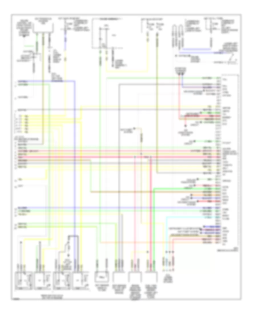
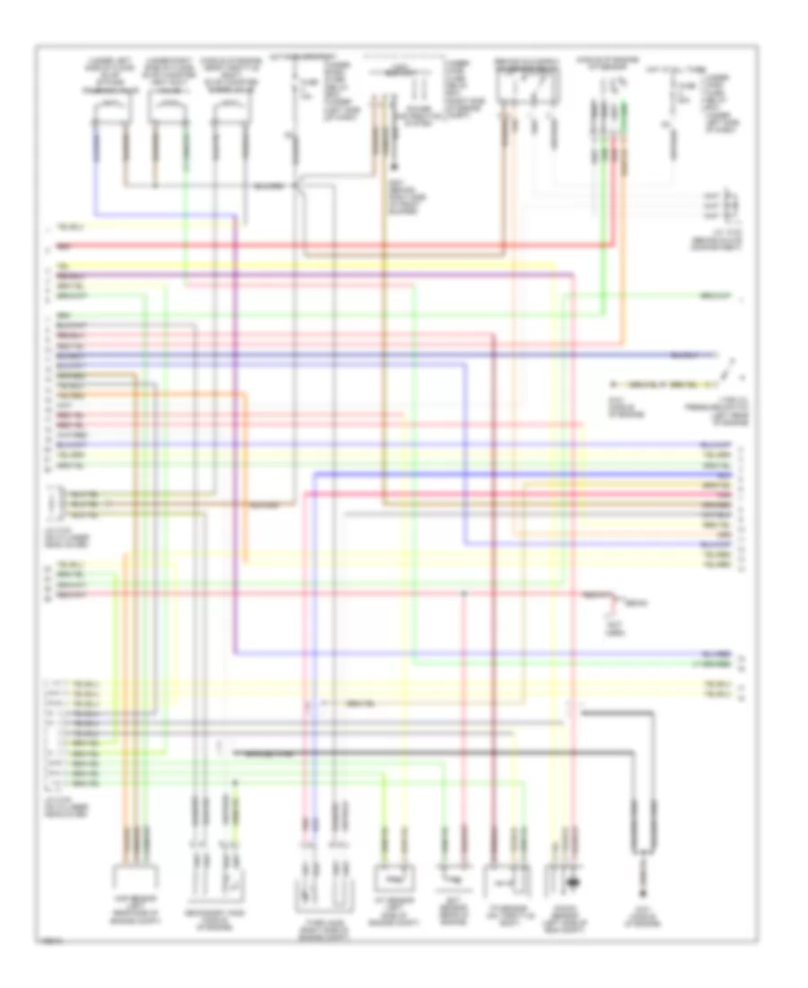
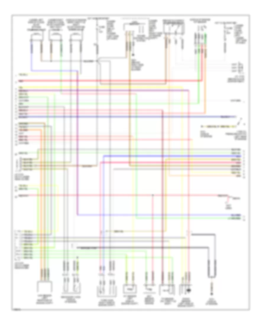
1.3L
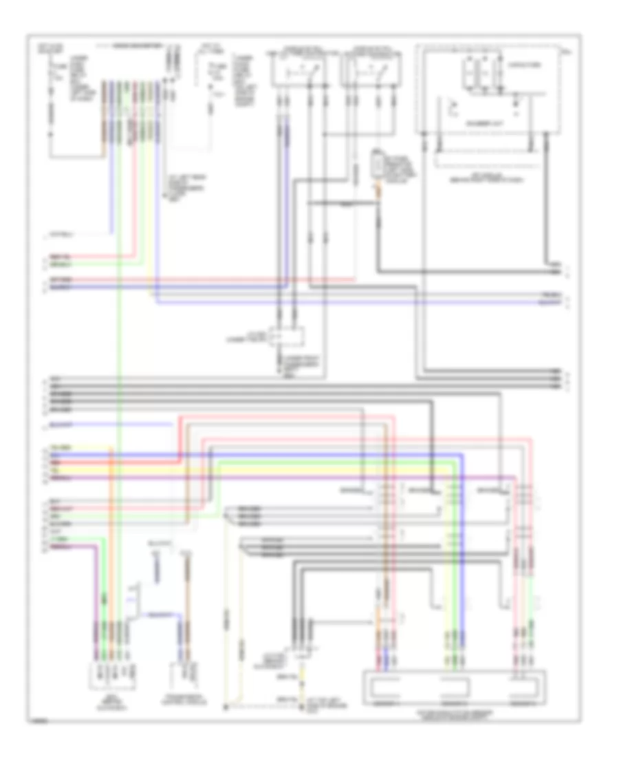
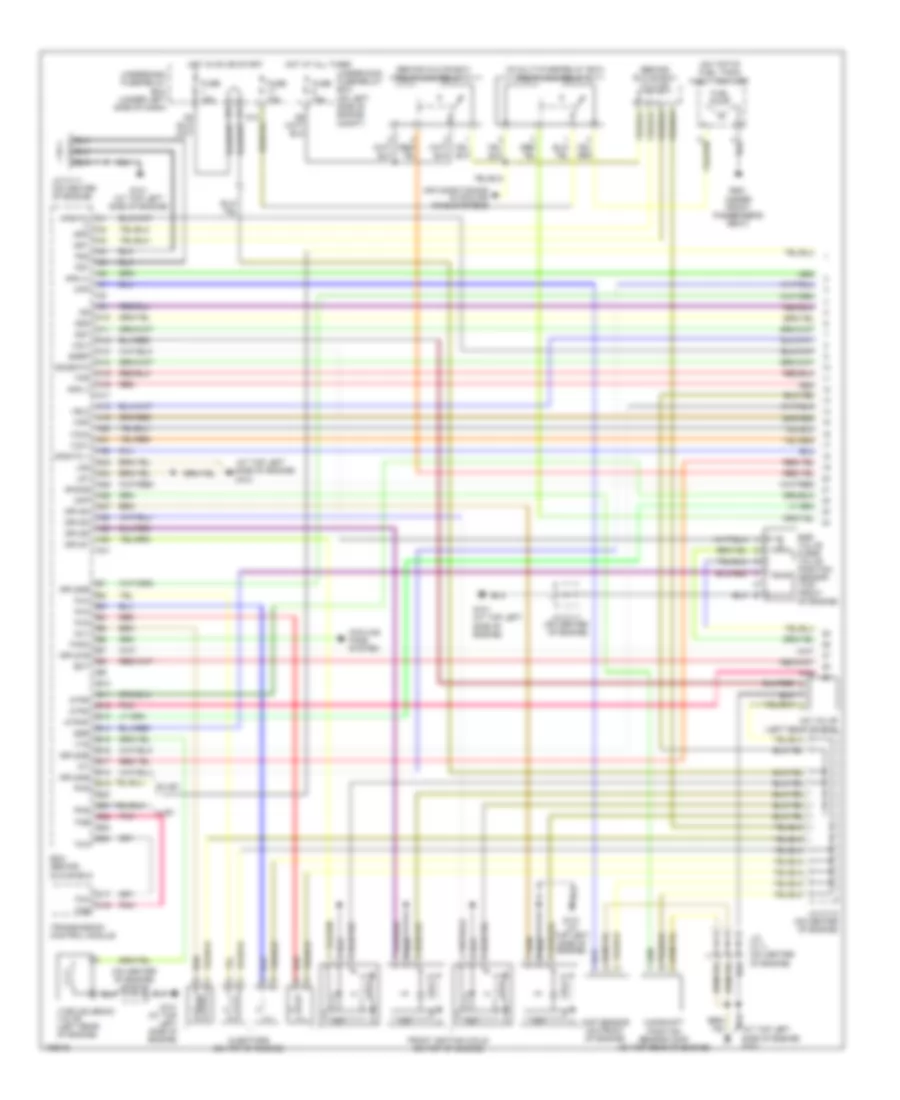
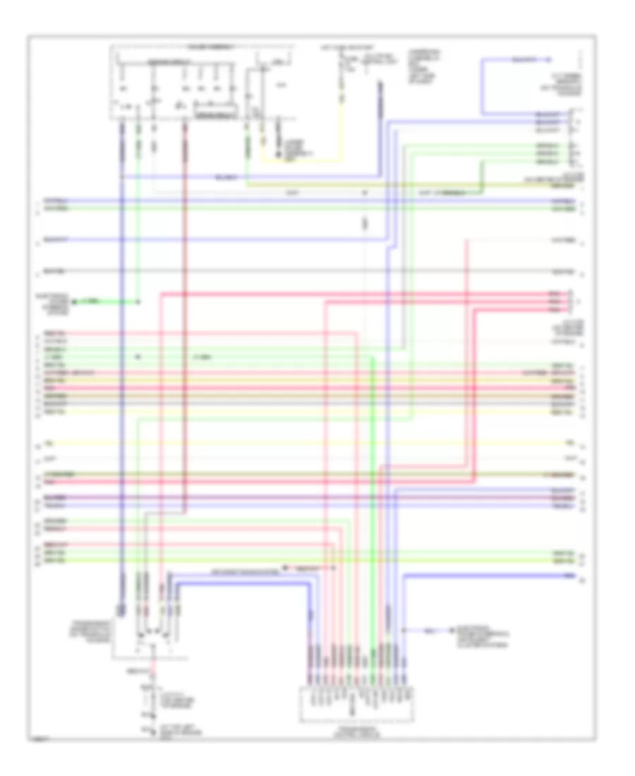
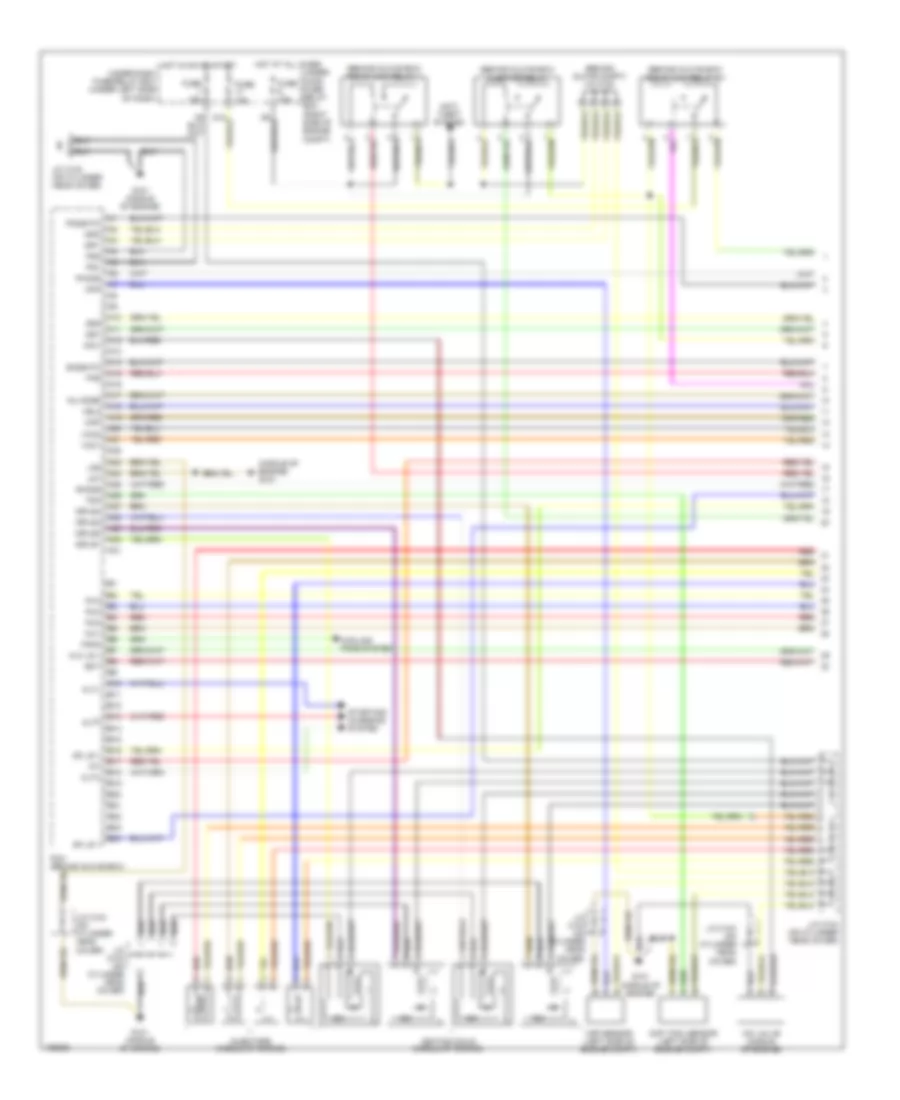
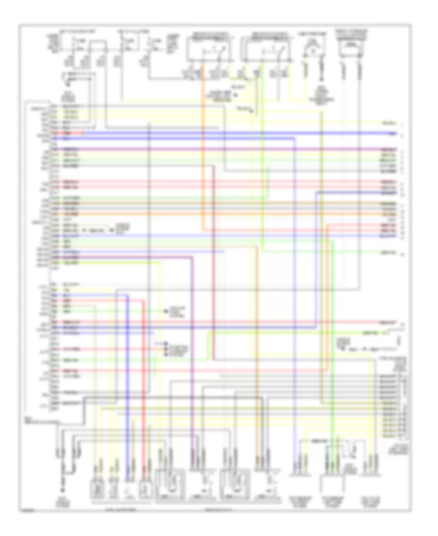
1.3L, Engine Performance Wiring Diagram, A/T (1 of 4) for Honda Civic GX 2005
List of elements for 1.3L, Engine Performance Wiring Diagram, A/T (1 of 4) for Honda Civic GX 2005:
- (-)
- (at top left side of engine) g101
- (behind glove box) j/c c106
- (behind glove box) pgm-fi main relay 1
- (in multi-fuse/relay box) pgm-fi main relay 2
- (on center of engine)
- (on center of engine) j/c c111
- (on top of fuel tank) fuel tank unit
- A10
- A11
- A12
- A13
- A14
- A15
- A16
- A17
- A18
- A19
- A20
- A21
- A22
- A23
- A24
- A25
- A26
- A27
- A28
- A29
- A30
- A31
- Afs (+)
- Afs (-)
- Afshtc +
- Afshtc a1
- Air conditioning & cooling fans systems
- Atpd
- Atpnp
- Atpr
- B10
- B11
- B12
- B13
- B14
- B15
- B16
- B17
- B18
- B19
- B20
- B21
- B22
- B23
- B24
- C16
- C17
- Camshaft position sensor (cmp) (on top rear of engine)
- Ckp
- Ckp sensor (on front of engine)
- Cmp
- Cooling fans system
- Ecm (behind glove box)
- Ect
- Egr
- Egr valve & egr valve position sensor (top front of engine)
- Egrp
- Fanc
- Front ignition coils (on top of engine)
- Fuel pump
- Fuse 15a
- G101 (at top left side of engine)
- G551 (under front passenger's seat)
- Hot at all times
- Hot in on or start
- Iac valve (left rear of eng)
- Iacv
- Iat
- Icm
- Igp1
- Igp2
- Igpls1
- Igpls1e
- Igpls2
- Igpls2e
- Igpls3
- Igpls3e
- Igpls4
- Igpls4e
- Inj1
- Inj2
- Inj3
- Inj4
- Injectors (on top of engine)
- J/c c110 (on center of engine)
- J/c c111
- J/c c111 (on center of engine)
- Lg1
- Lg2
- Map
- Pcs
- Pg1
- Pg2
- Pnk
- Red
- Sg1
- Sg2
- Sho2s
- So2shtc
- Sulev
- Tma
- Tmb
- Tps
- Transmission control module
- Ulev
- Underdash fuse/relay box (under left side of dash)
- Underhood fuse/relay box (on left side of engine compt)
- Vcc1
- Vcc2
- Vel2
- Vtec solenoid valve (left rear of engine)
- Vts
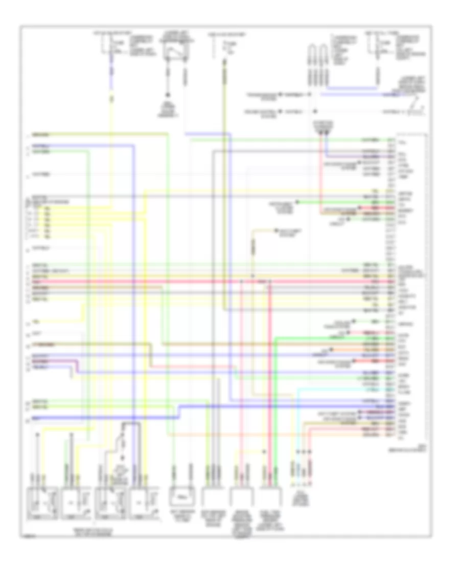
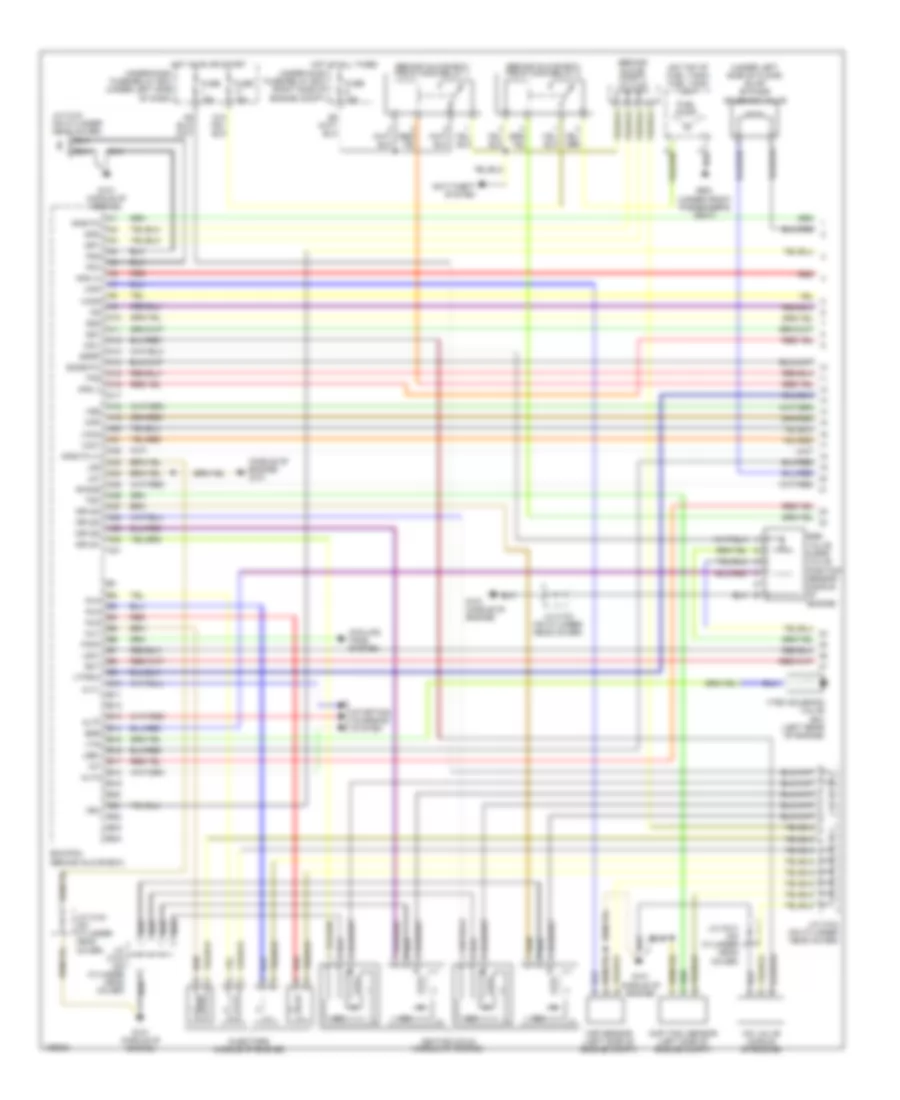
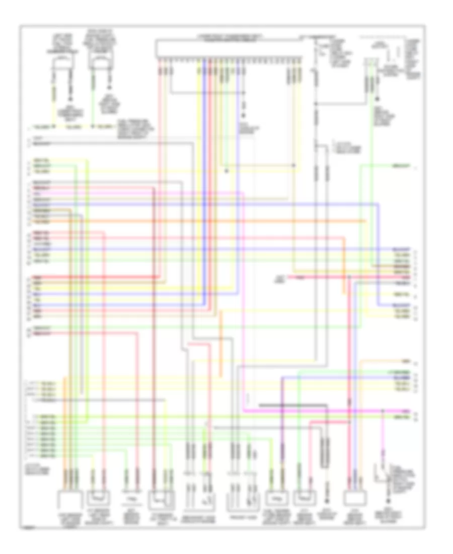
1.3L, Engine Performance Wiring Diagram, A/T (2 of 4) for Honda Civic GX 2005
List of elements for 1.3L, Engine Performance Wiring Diagram, A/T (2 of 4) for Honda Civic GX 2005:
- (behind glove box) a/f diode
- (behind glove box) a/f sensor relay
- (behind glove box) j/c c106
- (middle of engine) evap canister purge valve
- (on transaxle housing) a/f sensor
- (sulev)
- (ulev)
- (under left side of floor) (ulev) evap by-pass solenoid valve
- (under right side of floor) evap canister vent shut valve
- Braided wire
- Eld unit
- Engine coolant temperature (ect) sensor (rear of engine)
- Fuse 10a
- Fuse 20a
- G101 (at top left side of engine)
- G301 (behind left side of front bumper)
- Hot at all times
- Hot in on or start
- Ima circuit
- Intake air temperature (iat) sensor (on center of engine)
- J/c c111 (on center of engine)
- J/c c106 (behind glove box)
- J/c c110 (on center of engine)
- J/c c111 (on center of engine)
- Knock sensor (on left side of engine block)
- Map sensor (left rear side of engine)
- Pnk
- Power distribution system
- Red
- Secondary ho2s (left side of engine compt)
- Secondary ho2s (ulev) (middle of engine compt)
- Third ho2s
- Tp sensor (on throttle body)
- Under dash fuse/ relay box (under left side of dash)
- Under hood fuse/ relay box (on left side of engine compt)
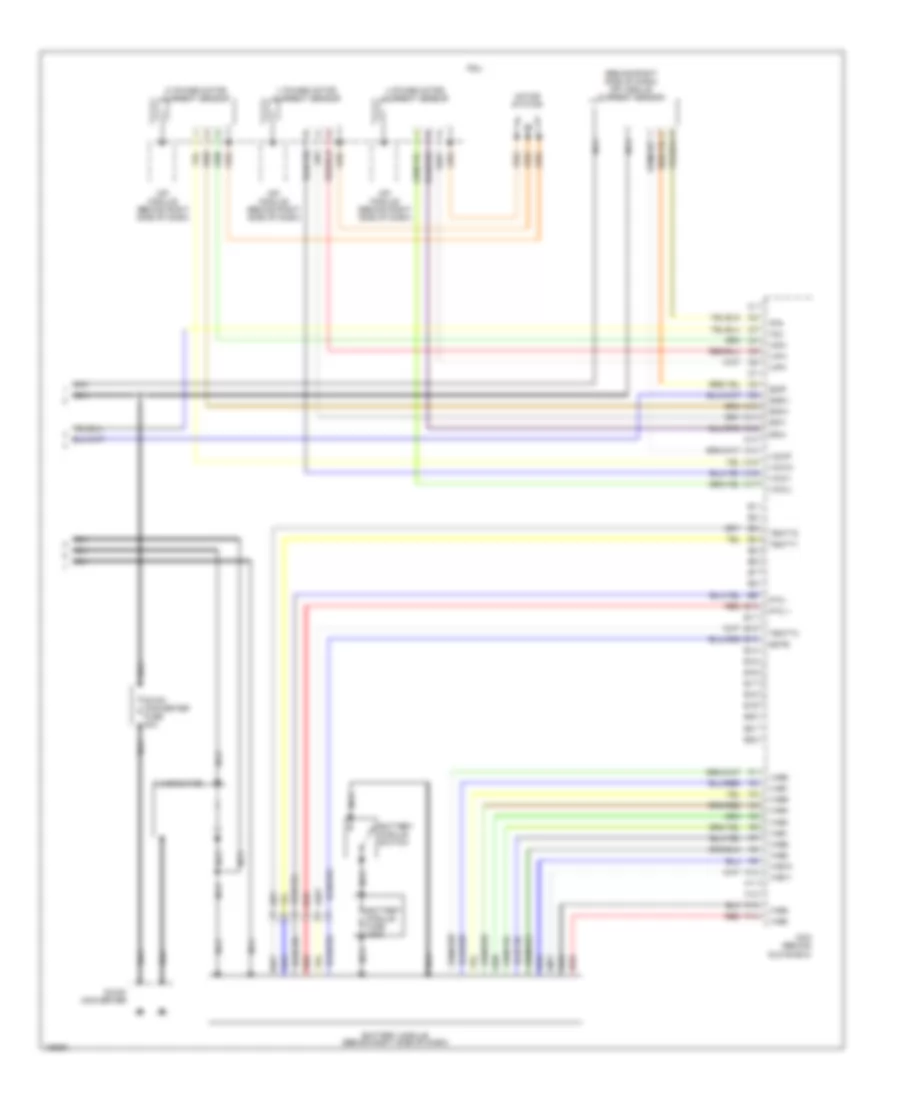
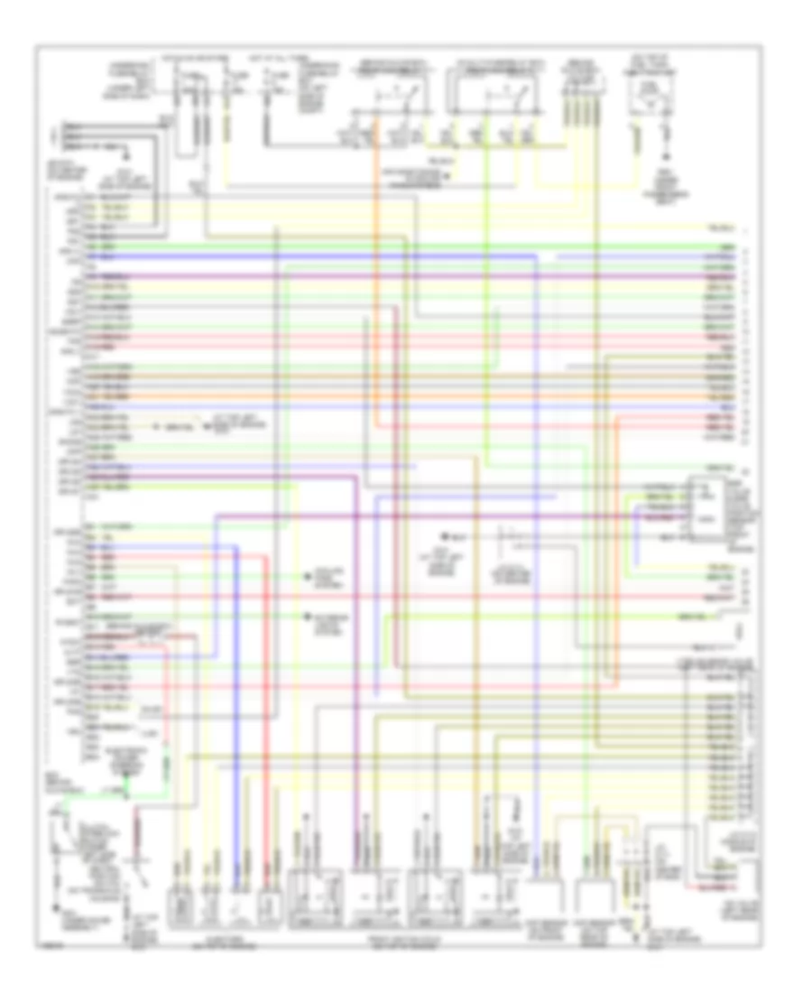
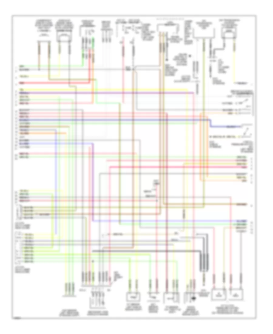
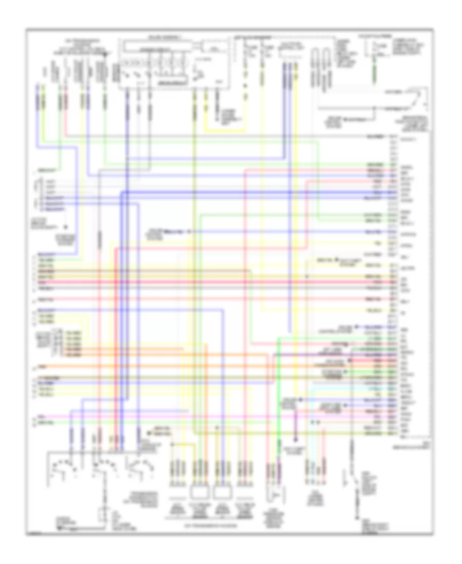
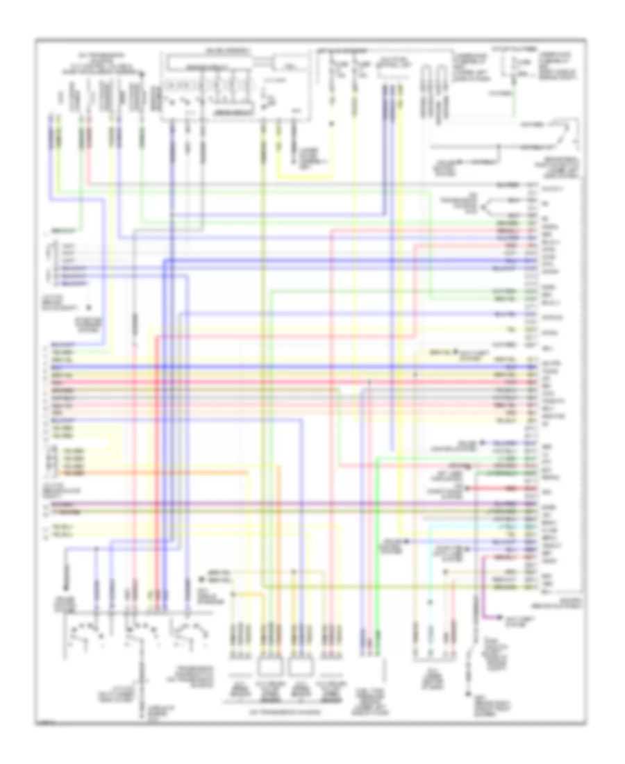
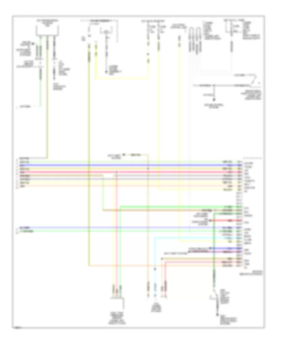
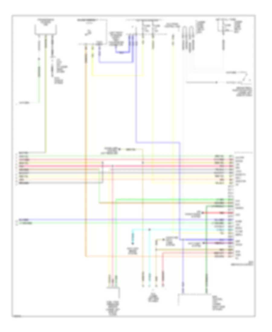
1.3L, Engine Performance Wiring Diagram, A/T (3 of 4) for Honda Civic GX 2005
List of elements for 1.3L, Engine Performance Wiring Diagram, A/T (3 of 4) for Honda Civic GX 2005:
- (at top left side of engine) g101
- (under gauge assembly) g501
- A15
- A16
- A17
- A18
- A19
- A28
- Air conditioning system
- Atp d
- Atp l
- Atp np
- Atp r
- Atp s
- B10
- B17
- B20
- C10
- C11
- C13
- C14
- Cpu
- Cvt speed sensor 2 (on transaxle housing)
- D10
- Dimming circuit
- Drive circuit
- Ect
- Electronic power steering & instrument cluster systems
- Electronic power steering system
- Fuse 7.5a
- Gauge assembly
- Hot in on or start
- Iat
- J/c c109 (on center of engine)
- J/c c111 (on center of engine)
- Map (pb)
- Mil ind
- Multiplex control unit
- Nep
- Pnk
- Red
- Rscd
- Tps
- Transmission control module
- Transmission range switch (on transaxle housing)
- Underdash fuse/relay box (under left side of dash)
- Vel2
- Vref
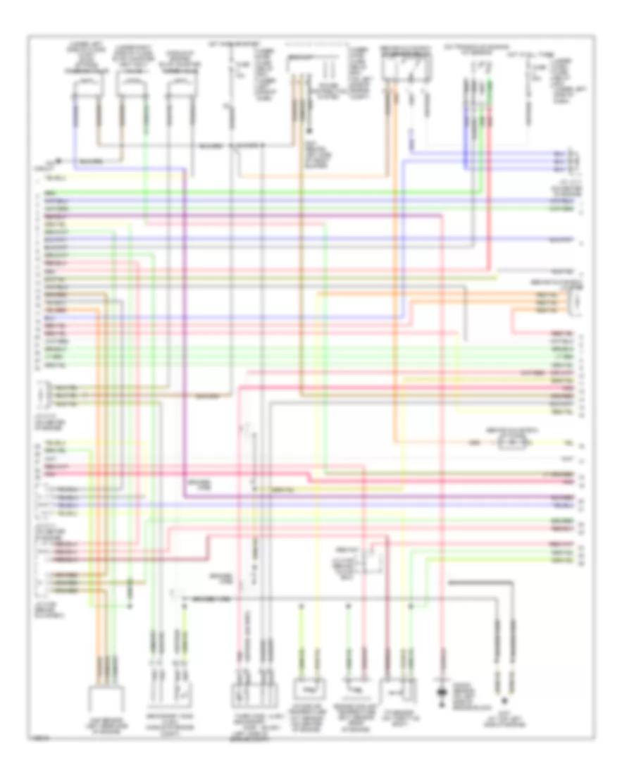
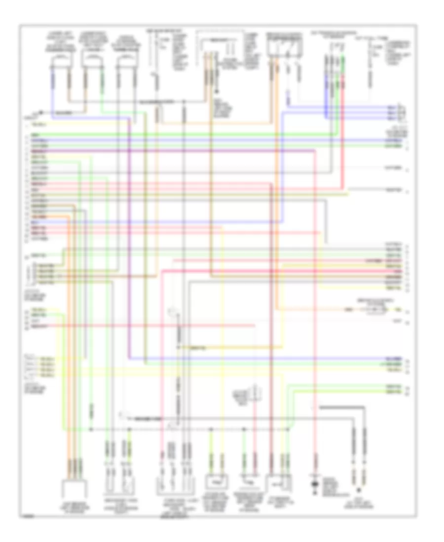
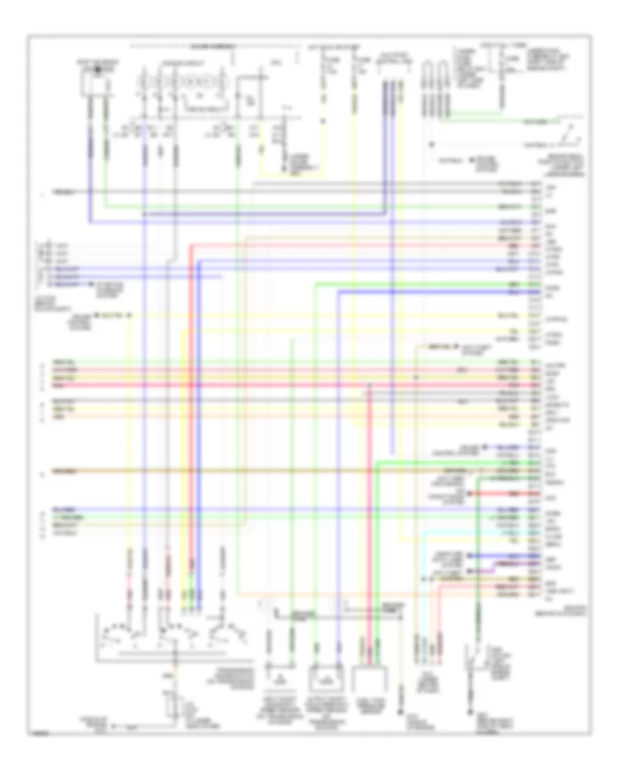
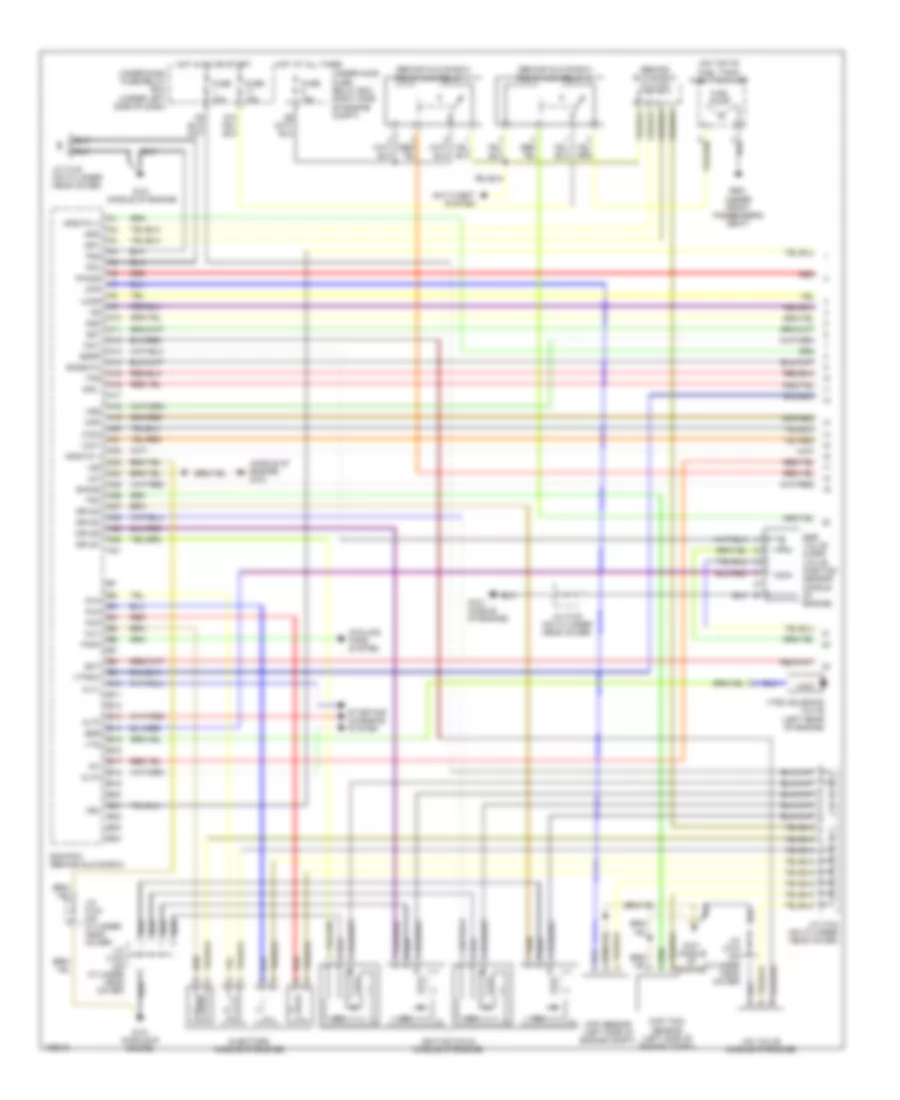
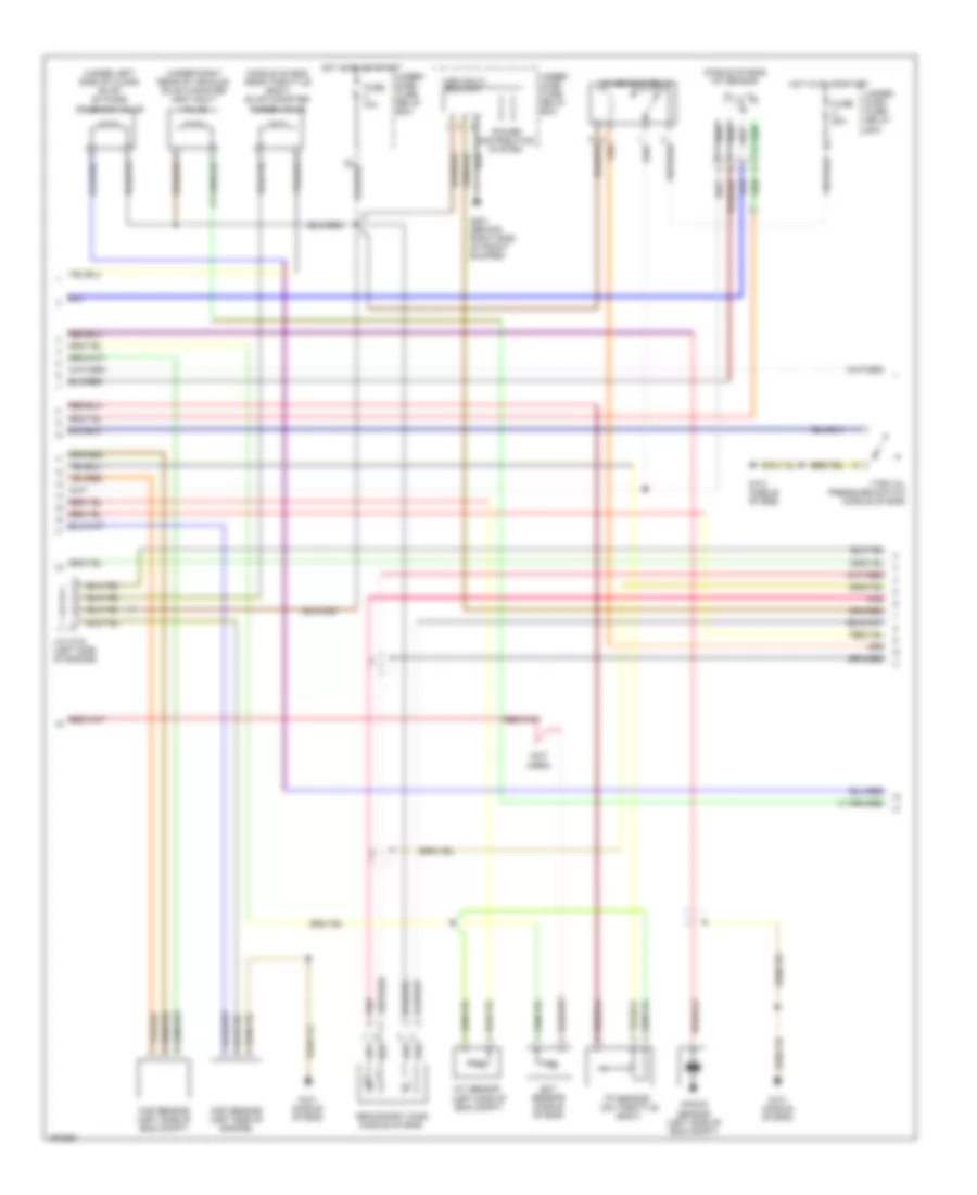
1.3L, Engine Performance Wiring Diagram, A/T (4 of 4) for Honda Civic GX 2005
List of elements for 1.3L, Engine Performance Wiring Diagram, A/T (4 of 4) for Honda Civic GX 2005:
- (on center of engine) j/c c110
- (ulev) (sulev)
- (under left side of dash) brake pedal position switch
- (under left side of dash) idle stop switch
- 2wbs
- Acc
- Acs
- Afshtcr
- Air conditioning system
- Anti-theft system
- Bksw
- Brake booster pressure sensor (left side of engine compt)
- C10
- C11
- C12
- C13
- C14
- C15
- C16
- C17
- C18
- C19
- C20
- C21
- C22
- Cooling fans system
- Cruise control system
- Dlc (under center of dash)
- Dvc
- E10
- E11
- E12
- E13
- E14
- E15
- E16
- E17
- E18
- E19
- E20
- E21
- E22
- E23
- E24
- E25
- E26
- E27
- E28
- E29
- E30
- E31
- Ecm (behind glove box)
- Eld
- Engrdy
- Eop sensor (on top left rear of engine)
- Eot sensor (near oil filter)
- Ftp
- Fuel tank pressure sensor (under left side of floor)
- Fuse 15a
- G101 (at top left side of engine)
- G501 (under gauge assembly)
- Ho2shtc
- Hot at all times
- Hot in on or start
- Hrfanc
- Htrs
- Icm
- Idssw
- Ig1
- Igrtne
- Igrtni
- Ima circuit
- Imo fpr tho2s sho2s lg3
- Imocd
- Instrument cluster system
- K-line
- M/p mon
- Mil
- Mota
- Motb
- Mrly
- Nep
- P12
- Pnk
- Poil
- Rear ignition coils (on top of engine)
- Red
- Rscd
- Scs
- Sg3
- Starting/ charging system
- Stc
- Sts
- Tim
- Toil
- Transmissions system
- Underdash fuse/relay box (under left side of dash)
- Underhood fuse/relay box (on left side of engine compt)
- Vcc3
- Vref
- Vsv
- Wen
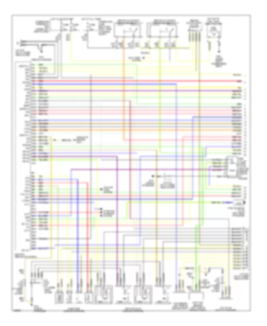
1.3L, Engine Performance Wiring Diagram, M/T (1 of 3) for Honda Civic GX 2005
List of elements for 1.3L, Engine Performance Wiring Diagram, M/T (1 of 3) for Honda Civic GX 2005:
- (at top left side of engine) g101
- (behind glove box)
- (behind glove box) j/c c106
- (behind glove box) pgm-fi main relay 1
- (in multi-fuse/relay box) pgm-fi main relay 2
- (on center of engine)
- (on top of fuel tank) fuel tank unit
- A1 afshtc (-) igp2
- A10
- A11
- A12
- A13
- A14
- A15
- A16
- A17
- A18
- A19
- A20
- A21
- A22
- A23
- A24
- A25
- A26
- A27
- A28
- A29
- A30
- A31
- Afs (+)
- Afs (-)
- Afshtc +
- Air conditioning & cooling fans systems
- Altf
- B10
- B11
- B12
- B13
- B14
- B15
- B16
- B17
- B18
- B19
- B20
- B21
- B22
- B23
- B24
- Ckp
- Ckp sensor (on front of engine)
- Clutch interlock switch (under left side of dash)
- Cmp
- Cmp sensor (on top rear of engine)
- Cooling fans system
- D12
- Ecm (behind glove box)
- Ect
- Egr
- Egr valve & egr valve position sensor (top front of engine)
- Egrp
- Electronic power steering system
- Exterior lights system
- Fanc
- Front ignition coils (on top of engine)
- Fuel pump
- Fuse 15a
- G101 (at top left side of engine)
- G401 (under gauge assembly)
- G551 (under front passenger's seat)
- Hot at all times
- Hot in on or start
- Iac valve (left rear of engine)
- Iacv
- Iat
- Icm
- Igp1
- Igpls1
- Igpls1e
- Igpls2
- Igpls2e
- Igpls3
- Igpls3e
- Igpls4
- Igpls4e
- Inj1
- Inj2
- Inj3
- Inj4
- Injectors (on top of engine)
- J/c c106
- J/c c110 (middle of engine)
- J/c c111
- J/c c111 (on center of eng)
- J/c c111 j/c c111 (on center of engine)
- Lg1
- Lg2
- Map
- Neutral position switch (on transaxle housing)
- Ntsw
- Pcs
- Pg1
- Pg2
- Red
- Rvssw
- Sg1
- Sg2
- Sho2s
- So2shtc
- Sulev
- Tps
- Ulev
- Underdash fuse/relay box (under left side of dash)
- Underhood fuse/relay box (on left side of engine compt)
- Vbu
- Vcc1
- Vcc2
- Vss
- Vtec solenoid valve (left rear of engine)
- Vts
1.3L, Engine Performance Wiring Diagram, M/T (2 of 3) for Honda Civic GX 2005
List of elements for 1.3L, Engine Performance Wiring Diagram, M/T (2 of 3) for Honda Civic GX 2005:
- (behind glove box) a/f diode
- (behind glove box) a/f sensor relay
- (middle of engine) evap canister purge valve
- (on transaxle housing) a/f sensor
- (sulev)
- (ulev)
- (under left side of floor) (ulev) evap by-pass solenoid valve
- (under right side of floor) evap canister vent shut valve
- Braided
- Braided wire
- Eld unit
- Engine coolant temperature (ect) sensor (rear of engine)
- Fuse 10a
- Fuse 20a
- G101 (at top left side of engine)
- G301 (behind left side of front bumper)
- Hot at all times
- Hot in on or start
- Ima circuit
- Intake air temperature (iat) sensor (on center of engine)
- J/c c111 (on center of engine)
- J/c c106 (behind glove box)
- J/c c110 (on center of engine)
- J/c c111 (on center of engine)
- Knock sensor (on left side of engine block)
- Map sensor (left rear side of engine)
- Pnk
- Power distribution system
- Red
- Secondary ho2s (left side of engine compt)
- Secondary ho2s (ulev) (middle of engine compt)
- Third ho2s
- Tp sensor (on throttle body)
- Under dash fuse/ relay box (under left side of dash)
- Under hood fuse/ relay box (on left side of engine compt)
- Underdash fuse/relay box (under left side of dash)
1.3L, Engine Performance Wiring Diagram, M/T (3 of 3) for Honda Civic GX 2005
List of elements for 1.3L, Engine Performance Wiring Diagram, M/T (3 of 3) for Honda Civic GX 2005:
- (on transaxle housing) vss
- (ulev) (sulev)
- (under gauge assembly) g501
- (under left side of dash) brake pedal position switch
- 2wbs
- A17
- Acc
- Acs
- Afshtcr
- Air conditioning system
- Anti-theft system
- B17
- Bksw
- Brake booster pressure sensor (left side of engine compt)
- C10
- C11
- C12
- C13
- C14
- C15
- C16
- C17
- C18
- C19
- C20
- C21
- C22
- Cooling fans system
- Cpu
- Cruise control system
- Cruise control, air conditioning, & electronic power steering systems
- Cylout
- Dlc (under center of dash)
- Dvc
- E10
- E11
- E12
- E13
- E14
- E15
- E16
- E17
- E18
- E19
- E20
- E21
- E22
- E23
- E24
- E25
- E26
- E27
- E28
- E29
- E30
- E31
- Ecm (behind glove box)
- Eld
- Engrdy
- Eop sensor (on top left rear of engine)
- Eot sensor (near oil filter)
- Ftp
- Fuel tank pressure sensor (under left side of floor)
- Fuse 15a
- Fuse 7.5a
- G101 (at top left side of engine)
- Gauge assembly
- Hot at all times
- Hot in on or start
- Hrfanc
- Htrs
- Icm
- Ig1
- Igrtne
- Igrtni
- Ima circuit
- Imo fpr tho2s sho2s lg3
- Imocd
- Instrument cluster system
- J/c c110 (on center of engine)
- J/c c103 (under right side of dash)
- J/c c106 (behind glove box)
- K-line
- M/p mon
- Mil
- Mil ind
- Mota
- Motb
- Mrly
- Nep
- P12
- Pnk
- Poil
- Rear ignition coils (on top of engine)
- Red
- Rscd
- Scs
- Sg3
- Starting/ charging system
- Stc
- Sts
- Tim
- To2shtc
- Toil
- Underdash fuse/relay box (under left side of dash)
- Underhood fuse/relay box (on left side of engine compt)
- Vcc3
- Vsv
- Wen
1.7L
1.7L, Engine Performance Wiring Diagram, Except HX & GX (1 of 3) for Honda Civic GX 2005
List of elements for 1.7L, Engine Performance Wiring Diagram, Except HX & GX (1 of 3) for Honda Civic GX 2005:
- (behind glove box) pgm-fi main relay 1
- (behind glove box) pgm-fi main relay 2
- (behind glove compt) j/c c102
- (middle of engine) g101
- (on top of fuel tank) fuel tank unit
- (under left side of floor) evap bypass solenoid valve
- A10
- A11
- A12
- A13
- A14
- A15
- A16
- A17
- A18
- A19
- A20
- A21
- A22
- A23
- A24
- A25
- A26
- A27
- A28
- A29
- A30
- A31
- Afs (+)
- Afs (-)
- Afshtc
- Afshtc (+)
- Altc
- Altf
- Altl
- Anti-theft system
- B10
- B11
- B12
- B13
- B14
- B15
- B16
- B17
- B18
- B19
- B20
- B21
- B22
- B23
- B24
- Ckp
- Ckp sensor (left side of engine compt)
- Cmp (tdc) sensor (left side of engine compt)
- Cooling fans system
- Ecm/pcm (behind glove box)
- Ect
- Egr
- Egr valve & egr valve position sensor (middle of engine)
- Egrp
- Fanc
- Fuel pump
- Fuse 15a
- G101 (middle of engine)
- G551 (under front passenger's seat)
- Hot at all times
- Hot in on or start under-dash fuse/relay box (under left side of dash)
- Iac valve (middle of engine)
- Iacv
- Iat
- Icm
- Ignition coils (middle of engine)
- Igp1
- Igp2
- Igpls1
- Igpls2
- Igpls3
- Igpls4
- Inj1
- Inj2
- Inj3
- Inj4
- Injectors (middle of engine)
- J/c c103 (on cylinder head cover)
- J/c c104 (on cylinder head cover)
- Lg1
- Lg2
- Lsa+
- Lsb+
- Map
- Pg1
- Pg2
- Red
- Sg1
- Sg2
- Sho2s
- So2shtc
- Starting/ charging system
- Tdc
- Tps
- Under-hood fuse/relay box (right side of engine compt)
- Vbu
- Vcc1
- Vcc2
- Vccr
- Vss
- Vtec solenoid valve (ex) (left rear of engine)
- Vtpsw
- Vts
1.7L, Engine Performance Wiring Diagram, Except HX & GX (2 of 3) for Honda Civic GX 2005
List of elements for 1.7L, Engine Performance Wiring Diagram, Except HX & GX (2 of 3) for Honda Civic GX 2005:
- (behind glove box) a/f sensor relay
- (behind glove compt) j/c c102
- (middle of engine) a/f sensor
- (middle of engine, near throttle body) evap canister purge valve
- (not used)
- (on transmission housing) tcc solenoid valve
- (on transmission housing) vss
- (under right side of floor) evap canister vent shut valve
- (usa) eld unit
- A/t clutch pressure control solenoid valves (on transmission housing)
- Braided wire
- Cruise control & instrument cluster systems
- Dx/lx
- Ect sensor (rear of engine)
- Fuse 10a
- Fuse 20a
- G101 (middle of engine)
- G201 (behind right side of front bumper)
- Hot at all times
- Hot in on or start
- Iat sensor (left side of engine compt)
- J/c c102 (behind glove compt)
- J/c c103 (on cylinder head cover)
- J/c c104 (on cylinder head cover)
- Knock sensor (left side of engine compt)
- Map sensor (left rear side of engine compt)
- Not used except ex
- Pnk
- Power distribution system
- Red
- Secondary ho2s (middle of engine)
- Sedan
- Tp sensor (on throttle body)
- Under- dash fuse/ relay box (under left side of dash)
- Under- hood fuse/ relay box (right side of engine compt)
- Vtec oil pressure switch (ex) (left rear of engine)
1.7L, Engine Performance Wiring Diagram, Except HX & GX (3 of 3) for Honda Civic GX 2005
List of elements for 1.7L, Engine Performance Wiring Diagram, Except HX & GX (3 of 3) for Honda Civic GX 2005:
- (ex)
- (middle of engine) g101
- (not used for canada)
- (under gauge assembly) g501
- 2wbs
- A11
- A15
- A16
- A17
- Acc
- Afshtcr
- Air conditioning system
- Anti-theft system
- Atp2
- Atpd3
- Atpd4
- Atpfwd
- Atpnp
- Atpr
- B11
- B17
- B21
- Bksw
- Braided wire
- Brake pedal position switch (under left side of dash)
- C10
- C11
- C12
- C13
- C14
- C15
- C16
- C17
- C18
- C19
- C20
- C21
- C22
- Ccs
- Computer data lines system
- Cpu
- Cruise control system
- D10
- Dimming circuit
- Dlc (under center of dash)
- Drive circuit
- E10
- E11
- E12
- E13
- E14
- E15
- E16
- E17
- E18
- E19
- E20
- E21
- E22
- E23
- E24
- E25
- E26
- E27
- E28
- E29
- E30
- E31
- Ecm/pcm (behind glove box)
- Eld
- Ftp
- Fuel tank pressure sensor
- Fuse 15a
- Fuse 7.5a
- G101 (middle of engine)
- G201 (behind right side of front bumper)
- Gauge assembly
- Hot at all times
- Hot in on or start
- Ig1
- Ilu
- Imo fpr
- Imocd
- Input shaft (mainshaft) speed sensor (on transmission housing)
- J/c c102 (behind glove compt)
- J/c c103 (on cylinder head cover)
- K-line
- Lg3
- Lsa-
- Lsb-
- Lx, ex
- Mil
- Mil ind
- Mrly
- Multiplex control unit
- Ncsg
- Nep
- Nmsg
- Output shaft (countershaft) speed sensor (on transmission housing)
- Pnk
- Psp switch (left side of engine compt)
- Pspsw
- Red
- Scs
- Sefmj
- Sg3
- Sha
- Shb
- Shift solenoid valve a & b
- So2s
- So2shtc
- Starting/ charging system
- Transmission range switch (on transmission housing)
- Under- dash fuse/ relay box (under left side of dash)
- Under-hood fuse/relay box (right side of engine compt)
- Vcc3
- Vsv
- Wen input
1.7L, Engine Performance Wiring Diagram, GX (1 of 3) for Honda Civic GX 2005
List of elements for 1.7L, Engine Performance Wiring Diagram, GX (1 of 3) for Honda Civic GX 2005:
- (behind glove box) injector relay
- (behind glove box) pgm-fi main relay 1
- (behind glove box) pgm-fi main relay 2
- (behind glove compt) j/c c102
- (middle of engine) g101
- A10
- A11
- A12
- A13
- A14
- A15
- A16
- A17
- A18
- A19
- A20
- A21
- A22
- A23
- A24
- A25
- A26
- A27
- A28
- A29
- A30
- A31
- Altc
- Altf
- Altl
- Anti- theft system
- B10
- B11
- B12
- B13
- B14
- B15
- B16
- B17
- B18
- B19
- B20
- B21
- B22
- B23
- B24
- Ckp
- Ckp sensor (left side of engine compt)
- Cmp (tdc) sensor (left side of engine compt)
- Cooling fans system
- Ect
- Fanc
- Fuse 15a
- G101 (middle of engine)
- Hlc ls +
- Hot at all times
- Hot in on or start
- Iac valve (middle of engine)
- Iacv
- Iat
- Icm
- Ignition coils (middle of engine)
- Igp1
- Igp2
- Igpls1
- Igpls2
- Igpls3
- Igpls4
- Inj mode
- Inj1
- Inj2
- Inj3
- Inj4
- Injectors (middle of engine)
- J/c c103 (on cylinder head cover)
- J/c c104 (on cylinder head cover)
- Lg1
- Lg2
- Map
- Pcm (behind glove box)
- Pg1
- Pg2
- Pho2s
- Po2shtc
- Red
- Sc ls +
- Sg1
- Sg2
- Sh ls +
- Sho2s
- So2shtc
- Starting/ charging system
- Tdc
- Tps
- Under- hood fuse/ relay box (right side of engine compt)
- Under-dash fuse/relay box (under left side of dash)
- Vcc1
- Vcc2
- Vel2
1.7L, Engine Performance Wiring Diagram, GX (2 of 3) for Honda Civic GX 2005
List of elements for 1.7L, Engine Performance Wiring Diagram, GX (2 of 3) for Honda Civic GX 2005:
- (left side of trunk) fuel tank internal solenoid valve
- (not used)
- (righ side of engine compt) fuel pressure regulator shut- off solenoid valve
- (under front passenger's seat) injector control module
- (usa) eld unit
- Braided wire
- Ect sensor (rear of engine)
- Ftp sensor (behind rear seat)
- Ftt sensor (behind rear seat)
- Fuel pressure regulator leak check connector (right front of engine compt)
- Fuel pressure regulator switch (right side of engine compt)
- Fuel temper- ature sensor (left side of engine compt)
- Fuse 10a
- G101 (middle of engine)
- G201 (behind right side of front bumper)
- G551 (under front passenger's seat)
- Hot in on or start
- Iat sensor (left rear side of engine compt)
- J/c c103 (on cylinder head cover)
- J/c c104 (on cylinder head cover)
- Map sensor (left side of engine compt)
- Pnk
- Power distribution system
- Primary ho2s
- Red
- Secondary ho2s (middle of engine)
- Tp sensor (on throttle body)
- Under- dash fuse/ relay box (under left side of dash)
- Under- hood fuse/ relay box (right side of engine compt)
1.7L, Engine Performance Wiring Diagram, GX (3 of 3) for Honda Civic GX 2005
List of elements for 1.7L, Engine Performance Wiring Diagram, GX (3 of 3) for Honda Civic GX 2005:
- (middle of engine) g101
- (on transmission housing)
- (on transmission housing) cvt control valves & inhibitor solenoid assembly
- (under gauge assembly) g501
- A16
- A17
- Acc
- Air condi- tioning system
- Anti-theft system
- Atpd4
- Atpfwd
- Atpl
- Atpnp
- Atpr
- Atps
- B11
- B21
- Bksw
- Brake pedal position switch (under left side of dash)
- C10
- C11
- C12
- C13
- C14
- C15
- C16
- C17
- C18
- C19
- C20
- C21
- C22
- Computer data lines system
- Cpu
- Crs
- Cruise control system
- Cvt drive pulley speed sensor
- Cvt driven pulley speed sensor
- Cvt speed change
- Cvt speed sensor
- D10
- Dimming circuit
- Dlc (under center of dash)
- Drive circuit
- E10
- E11
- E12
- E13
- E14
- E15
- E16
- E17
- E18
- E19
- E20
- E21
- E22
- E23
- E24
- E25
- E26
- E27
- E28
- E29
- E30
- E31
- Eld
- Fuel pressure sensor (middle of engine)
- Fuse 15a
- Fuse 7.5a
- G101 (middle of engine)
- G201 (behind right side of front bumper)
- Gauge assembly
- Hlcls (-)
- Hot at all times
- Hot in on or start
- Ig1
- Ilu
- Imo fpr
- Imocd
- Inhsol
- J/c c102 (behind glove compt)
- J/c c103 (on cylinder head cover)
- K-line
- Lg3
- Mil
- Mil ind
- Mrly
- Multiplex control unit
- Ncsg
- Ndn
- Ndr
- Nep
- Not used for canada
- P1sw
- Pcm (behind glove box)
- Pf2
- Pfo
- Pnk
- Pressure cvt pulley
- Pressure cvt start
- Psp switch (left side of engine compt)
- Pspsw
- Red
- Scls (-)
- Scs
- Sefmj
- Sg3
- Shls (-)
- Solenoid inhibitor
- Starting/ charging system
- Stswc
- Tf2
- Tfo
- Transmission range switch (on transmission housing)
- Under- dash fuse/ relay box (under left side of dash)
- Under-hood fuse/relay box (right side of engine compt)
- Vcc3
- Vel1
- Vssout
- Wen
1.7L, Engine Performance Wiring Diagram, HX A/T (1 of 3) for Honda Civic GX 2005
List of elements for 1.7L, Engine Performance Wiring Diagram, HX A/T (1 of 3) for Honda Civic GX 2005:
- (behind glove box) pgm-fi main relay 1
- (behind glove box) pgm-fi main relay 2
- (behind glove compt) j/c c102
- (middle of engine) g101
- (on top of fuel tank) fuel tank unit
- A10
- A11
- A12
- A13
- A14
- A15
- A16
- A17
- A18
- A19
- A20
- A21
- A22
- A23
- A24
- A25
- A26
- A27
- A28
- A29
- A30
- A31
- Afs -
- Afshtc (-)
- Afshtc +
- Altc
- Altf
- Altl
- Anti-theft system
- B10
- B11
- B12
- B13
- B14
- B15
- B16
- B17
- B18
- B19
- B20
- B21
- B22
- B23
- B24
- Ckp
- Ckp sensor (left side of engine compt)
- Cmp (tdc) sensor (left side of engine compt)
- Cooling fans system
- Ecm/pcm (behind glove box)
- Ect
- Egr
- Egr valve & egr valve position sensor (middle of engine)
- Egrp
- Fanc
- Fuel pump
- Fuse 15a
- G101 (middle of engine)
- G551 (under front passenger's seat)
- Hlc ls +
- Hot at all times
- Hot in on or start
- Iac valve (middle of engine)
- Iacv
- Iat
- Icm
- Ignition coils (middle of engine)
- Igp1
- Igp2
- Igpls1
- Igpls2
- Igpls3
- Igpls4
- Inj1
- Inj2
- Inj3
- Inj4
- Injectors (middle of engine)
- J/c c103 (on cylinder head cover)
- J/c c104 (on cylinder head cover)
- Lg1
- Lg2
- Map
- Pg1
- Pg2
- Pho2s
- Red
- Sc ls +
- Sg1
- Sg2
- Sh ls +
- Sho2s
- So2shtc
- Starting/ charging system
- Tdc
- Tps
- Under-dash fuse/relay box (under left side of dash)
- Under-hood fuse/ relay box (right side of engine compt)
- Vbu
- Vcc1
- Vcc2
- Vccr
- Vel2
- Vtec solenoid valve (left rear of engine)
- Vtpsw
- Vts
1.7L, Engine Performance Wiring Diagram, HX A/T (2 of 3) for Honda Civic GX 2005
List of elements for 1.7L, Engine Performance Wiring Diagram, HX A/T (2 of 3) for Honda Civic GX 2005:
- (behind glove box) a/f sensor relay
- (middle of engine) a/f sensor
- (middle of engine, near throttle body) evap canister purge valve
- (not used)
- (under left side of floor) evap bypass solenoid valve
- (under right side of floor) evap canister vent shut valve
- (usa) eld unit
- Braided wire
- Ect sensor (rear of engine)
- Fuse 10a
- Fuse 20a
- G101 (middle of engine)
- G201 (behind right side of front bumper)
- Hot at all times
- Hot in on or start
- Iat sensor (left side of engine compt)
- J/c c102 (behind glove compartment)
- J/c c103 (on cylinder head cover)
- J/c c104 (on cylinder head cover)
- Knock sensor (left side of eng compt)
- Map sensor (left rear side of engine compt)
- Pnk
- Power distribution system
- Red
- Secondary ho2s (middle of engine)
- Sedan
- Third ho2s (right side of engine compt)
- Tp sensor (on throttle body)
- Under- dash fuse/ relay box (under left side of dash)
- Under- hood fuse/ relay box (right side of engine compt)
- Vtec oil pressure switch (left rear of engine)
1.7L, Engine Performance Wiring Diagram, HX A/T (3 of 3) for Honda Civic GX 2005
List of elements for 1.7L, Engine Performance Wiring Diagram, HX A/T (3 of 3) for Honda Civic GX 2005:
- (0n transmission housing) cvt control valves & inhibitor solenoid assembly
- (middle of engine) g101
- (on transmission housing)
- (on transmission housing) g102
- (under gauge assembly) g501
- 2wbs
- A11
- A15
- Acc
- Afshtor
- Air conditioning system
- Anti-theft system
- Atpd4
- Atpfwd
- Atpl
- Atpnp
- Atpr
- Atps
- B17
- Bksw
- Brake pedal position switch (under left side of dash)
- C10
- C11
- C12
- C13
- C14
- C15
- C16
- C17
- C18
- C19
- C20
- C21
- C22
- Computer data lines system
- Cpu
- Crs
- Cruise control system
- Cvt driven pulley speed sensor
- Cvt speed change
- Cvt speed sensor
- D10
- Dimming circuit
- Dlc (under center of dash)
- Drive circuit
- E10
- E11
- E12
- E13
- E14
- E15
- E16
- E17
- E18
- E19
- E20
- E21
- E22
- E23
- E24
- E25
- E26 e26
- E27
- E28
- E29
- E30
- E31
- Ecm/pcm (behind glove box)
- Eld
- Ftp
- Fuel tank pressure sensor (under left side of floor)
- Fuse 15a
- Fuse 7.5a
- G101 (middle of engine)
- G201 (behind right side of front bumper)
- Gauge assembly
- Hlcls (-)
- Hot at all times
- Hot in on or start
- Ig1
- Ilu
- Imo fpr
- Imocd
- Inhsol
- J/c c102 (behind glove compt)
- J/c c103 (on cylinder head cover)
- K-line
- Lg3
- Mil
- Mil ind
- Mrly
- Multiplex control unit
- Ncsg
- Ndn
- Ndr
- Nep
- Not used for canada
- Pnk
- Pressure cvt pulley
- Pressure cvt start
- Psp switch (left side of engine compt)
- Pspsw
- Red
- Scls (-)
- Scs
- Sefmj
- Sg3
- Shls (-)
- Solenoid inhibitor
- Starting/ charging system
- Tho2s
- To2shtc
- Transmission range switch (on transmission housing)
- Under-dash fuse/relay box (under left side of dash)
- Under-hood fuse/relay box (right side of engine compt)
- Vcc3
- Vel1
- Vssout
- Vsv
- Wen
1.7L, Engine Performance Wiring Diagram, HX M/T (1 of 3) for Honda Civic GX 2005
List of elements for 1.7L, Engine Performance Wiring Diagram, HX M/T (1 of 3) for Honda Civic GX 2005:
- (behind glove box) j/c c102
- (behind glove box) pgm-fi main relay 1
- (behind glove box) pgm-fi main relay 2
- (middle of engine) g101
- (on top of fuel tank) fuel tank unit
- A10
- A11
- A12
- A13
- A14
- A15
- A16
- A17
- A18
- A19
- A20
- A21
- A22
- A23
- A24
- A25
- A26
- A27
- A28
- A29
- A30
- A31
- Afs -
- Afshtc (-)
- Afshtc +
- Altc
- Altf
- Altl
- Anti-theft system
- B10
- B11
- B12
- B13
- B14
- B15
- B16
- B17
- B18
- B19
- B20
- B21
- B22
- B23
- B24
- Ckp
- Ckp sensor (left side of engine compt)
- Cmp (tdc) sensor (left side of engine compt)
- Cooling fans system
- Ecm/pcm (behind glove box)
- Ect
- Egr
- Egr valve & egr valve position sensor (middle of engine)
- Egrp
- Fanc
- Fuel pump
- Fuse 15a
- G101 (middle of engine)
- G551 (under front passenger's seat)
- Hot at all times
- Hot in on or start
- Iac valve (middle of engine)
- Iacv
- Iat
- Icm
- Ignition coils (middle of engine)
- Igp1
- Igp2
- Igpls1
- Igpls2
- Igpls3
- Igpls4
- Inj1
- Inj2
- Inj3
- Inj4
- Injectors (middle of engine)
- J/c c103 (on cylinder head cover)
- J/c c104 (on cylinder head cover)
- Lg1
- Lg2
- Map
- Pg1
- Pg2
- Pho2s
- Red
- Sg1
- Sg2
- Sho2s
- So2shtc
- Starting/ charging system
- Tdc
- Tps
- Under-dash fuse/relay box (under left side of dash)
- Under-hood fuse/ relay box (right side of engine compt)
- Vbu
- Vcc1
- Vcc2
- Vccr
- Vss
- Vtec solenoid valve (left rear of engine)
- Vtpsw
- Vts
1.7L, Engine Performance Wiring Diagram, HX M/T (2 of 3) for Honda Civic GX 2005
List of elements for 1.7L, Engine Performance Wiring Diagram, HX M/T (2 of 3) for Honda Civic GX 2005:
- (behind glove box) a/f sensor relay
- (middle of engine) a/f sensor
- (middle of engine, near throttle body) evap canister purge valve
- (not used)
- (under left side of floor) evap bypass solenoid valve
- (under right side of floor) evap canister vent shut valve
- (usa) eld unit
- Braided wire
- Ect sensor (rear of engine)
- Fuse 10a
- Fuse 20a
- G101 (middle of engine)
- G201 (behind right side of front bumper)
- Hot in on or start
- Iat sensor (left side of engine compt)
- J/c c102 (behind glove compartment)
- J/c c103 (on cylinder head cover)
- J/c c104 (on cylinder head cover)
- Knock sensor (left side of engine compt)
- Map sensor (left rear side of engine compt)
- Pnk
- Power distribution system
- Red
- Secondary ho2s (middle of engine)
- Sedan
- Third ho2s (right side of engine compt)
- Tp sensor (on throttle body)
- Under- dash fuse/ relay box (under left side of dash)
- Under- hood fuse/ relay box (right side of engine compt)
- Vtec oil pressure switch (left rear of engine)
1.7L, Engine Performance Wiring Diagram, HX M/T (3 of 3) for Honda Civic GX 2005
List of elements for 1.7L, Engine Performance Wiring Diagram, HX M/T (3 of 3) for Honda Civic GX 2005:
- (on transmission housing) vss
- (under gauge assembly) g501
- 2wbs
- A11
- A15
- Acc
- Afshtor
- Air conditioning system
- Anti-theft system
- Bksw
- Brake pedal position switch (under left side of dash)
- Computer data lines system
- Cpu
- Cruise control & instrument cluster systems
- Cruise control system
- Dlc (under center of dash)
- E10
- E11
- E12
- E13
- E14
- E15
- E16
- E17
- E18
- E19
- E20
- E21
- E22
- E23
- E24
- E25
- E26
- E27
- E28
- E29
- E30
- E31
- Ecm/pcm (behind glove box)
- Eld
- Ftp
- Fuel tank pressure sensor (under left side of floor)
- Fuse 15a
- Fuse 7.5a
- G101 (middle of engine)
- G201 (behind right side of front bumper)
- Gauge assembly
- Hot at all times
- Hot in on or start
- Ig1
- Imo fpr
- Imocd
- J/c c102 (behind glove compt)
- J/c c103 (on cylinder head cover)
- K-line
- Lg3
- Mil
- Mil ind
- Mrly
- Multiplex control unit
- Nep
- Not used for canada
- Pnk
- Psp switch (left side of engine compt)
- Pspsw
- Red
- Scs
- Sefmj
- Sg3
- Tho2s
- To2shtc
- Under- dash fuse/ relay box (under left side of dash)
- Under- hood fuse/ relay box (right side of engine compt)
- Vcc3
- Vsv
- Wen
2.0L
2.0L, Engine Performance Wiring Diagram (1 of 3) for Honda Civic GX 2005
List of elements for 2.0L, Engine Performance Wiring Diagram (1 of 3) for Honda Civic GX 2005:
- (behind glove box) pgm-fi main relay 1
- (behind glove box) pgm-fi main relay 2
- (front of engine) vtc oil control solenoid valve
- (middle of eng) g101
- A10
- A11
- A12
- A13
- A14
- A15
- A16
- A17
- A18
- A19
- A20
- A21
- A22
- A23
- A24
- A25
- A26
- A27
- A28
- A29
- A30
- A31
- Afs -
- Afshtc (-)
- Afshtc +
- Altc
- Altf
- Altl
- B10
- B11
- B12
- B13
- B14
- B15
- B16
- B17
- B18
- B19
- B20
- B21
- B22
- B23
- B24
- Box
- Ckp
- Ckp sensor (on front of eng)
- Cmp
- Cooling fans system
- Ecm (behind glove box)
- Ect
- Fanc
- Fuel injectors
- Fuel pump
- Fuel tank unit
- Fuse 15a
- G101 (middle of eng)
- G551 (under front passenger's seat)
- Hot at all times
- Hot in on or start under- dash fuse/ relay box
- Iac valve (left side of eng)
- Iacv
- Iat
- Icm
- Ignition coils
- Igp1
- Igp2
- Igpls1
- Igpls2
- Igpls3
- Igpls4
- Immobilizer control unit receiver
- Inj1
- Inj2
- Inj3
- Inj4
- J/c c104 (left side of engine)
- Lg1
- Lg2
- Map
- Pg1
- Pg2
- Pho2s
- Red
- Sg1
- Sg2
- Starting/ charging system
- Tdc
- Tdc sensor (left side of eng)
- Tps
- Under- hood fuse/ relay
- Vbu
- Vcc1
- Vcc2
- Vss
- Vtc +
- Vtc -
- Vtec solenoid valve (right of eng)
- Vtpsw
- Vts
2.0L, Engine Performance Wiring Diagram (2 of 3) for Honda Civic GX 2005
List of elements for 2.0L, Engine Performance Wiring Diagram (2 of 3) for Honda Civic GX 2005:
- (middle of eng) a/f sensor
- (middle of eng, near throttle body) evap canister purge valve
- (not used)
- (under left side of floor) evap by-pass solenoid valve
- (under right rear of vehicle) evap canister vent shut valve
- (usa only) eld unit
- A/f sensor relay
- Box
- Braided
- Cmp sensor (left side of engine)
- Ect sensor (middle of eng)
- Fuse 10a
- Fuse 20a
- G101 (middle of eng)
- G201 (behind right side of front bumper)
- Hot in on or start
- Iat sensor (left side of eng compt)
- J/c c104 (left side of engine)
- Knock sensor (left side of eng compt)
- Map sensor (left side of eng compt)
- Pnk
- Power distribution system
- Secondary ho2s (middle of eng)
- Tp sensor (on throttle body)
- Under- dash fuse/ relay
- Under- dash fuse/ relay box
- Under- hood fuse/ relay box
- Vtec oil pressure switch (middle of eng)
2.0L, Engine Performance Wiring Diagram (3 of 3) for Honda Civic GX 2005
List of elements for 2.0L, Engine Performance Wiring Diagram (3 of 3) for Honda Civic GX 2005:
- (left front of engine compt) test tachometer connector
- (transmission housing) vss
- 2wbs
- Acc
- Afshtor
- Air conditioning system
- Anti-lock brake system
- Anti-theft system
- Bksw
- Box
- Braided
- Brake pedal position switch (under left side of dash)
- C17
- C19
- Computer data lines system
- Dlc (under left side of dash)
- E10
- E11
- E12
- E13
- E14
- E15
- E16
- E17
- E18
- E19
- E20
- E21
- E22
- E23
- E24
- E25
- E26
- E27
- E28
- E29
- E30
- E31
- Ecm (behind glove box)
- Eld
- Eps control unit (under right side of dash)
- Ftp
- Fuel tank pressure sensor (under left side of floor)
- Fuse 15a
- Fuse 7.5a
- G101 (middle of eng)
- Gauge assembly
- Hot at all times
- Hot in on or start
- Ig1
- Immobilizer control unit receiver
- Imo fpr
- Imocd
- J/c c103 (on cylinder head cover)
- K-line
- Lg3
- Mil
- Mil ind
- Mrly
- Multiplex control unit
- Nep
- Pnk
- Pspsw
- Red
- Scs
- Sefmj
- Sg3
- Sho2s
- So2shtc
- Tach input
- Under- dash fuse/ relay
- Under- hood fuse/ relay
- Vcc3
- Vsv
- Wen