ENGINE PERFORMANCE
2.4L
2.4L, Engine Performance Wiring Diagram (1 of 4) for Honda CR-V EX 2008

List of elements for 2.4L, Engine Performance Wiring Diagram (1 of 4) for Honda CR-V EX 2008:
- (near fuel tank) evap canister vent shut valve
- (not used)
- A/c condenser fan diode
- A/c condenser fan relay
- A10
- A11
- A12
- A13
- A14
- A15
- A16
- A17
- A18
- A19
- A20
- A21
- A22
- A23
- A24
- A25
- A26
- A27
- A28
- A29
- A30
- A31
- A32
- A33
- A34
- A35
- A36
- A37
- A38
- A39
- A40
- A41
- A42
- A43
- A44
- Acc
- Acpd
- Afshtc
- Air conditioning system
- Anti-theft system
- App sensor (under left side of dash)
- Apsa
- Apsb
- B15
- B18
- B20
- B23
- Bksw
- Bkswnc
- C10
- C11
- C12
- C13
- C14
- C401
- Can-h
- Can-l
- Computer data lines system
- Cooling fans system
- D3 sw
- Eld
- Etc2
- Etcs control relay
- Etcsm+
- Etcsm-
- Etcsrly
- F10
- F13
- F16
- F18
- F19
- Fan-h
- Fan-l
- Ftp
- Fuse 15a
- Fuse 7.5a
- G101 (left side of engine)
- Hot at all times
- Ig1 etcs
- Ignition coil relay
- Igp
- Imo fpr
- Inj1
- Inj2
- Inj3
- Inj4
- Injectors (top of engine)
- J/c c101 (left rear of engine compt)
- J/c c103 (at rear of engine)
- Manifold absolute pressure sensor (top of throttle body)
- Map
- Mrly
- Output shaft (countershaft) speed sensor (on transmission housing)
- Pcm (left side of engine compt)
- Pgm-fi main relay 1
- Pgm-fi main sub relay
- Pgmetcs
- Pnk
- Pspsw
- Red
- S-net5v
- S1 (thermal joint)
- Scs
- Sg1
- Sg3
- Sg4
- Sg5
- Shift interlock system
- Sls
- Subrly
- Throttle actuator
- Throttle body (left rear of engine)
- Tp sensor
- Under-hood fuse/relay box (on left side of engine compt)
- Vcc1
- Vcc3
- Vcc4
- Vcc5
- Vcc6
- Vsp-out
- Vsv
- Wen
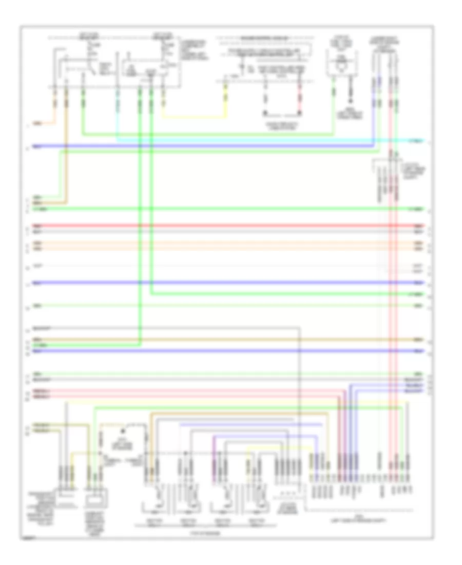
2.4L, Engine Performance Wiring Diagram (2 of 4) for Honda CR-V EX 2008
List of elements for 2.4L, Engine Performance Wiring Diagram (2 of 4) for Honda CR-V EX 2008:
- (top of engine)
- (top of fuel tank) fuel tank unit
- (under right side of engine compt) a/f sensor
- A14
- A15
- A23
- Afs+
- Afs-
- B10
- B16
- C15
- C16
- C17
- C18
- C19
- C20
- C21
- C22
- C23
- C24
- C25
- C26
- C27
- C28
- C29
- C30
- C31
- C32
- Camshaft position sensor b (rear of cylinder head)
- Ckp
- Cmp
- Computer data lines system
- Crankshaft position sensor (lower right front of engine, near crankshaft pulley)
- F10
- F24
- F25
- F30
- Fast controller area network controller
- Fuel pump
- Fuse 15a
- Fuse 7.5a
- G101 (left side of engine)
- G602 (left side of cargo area)
- Gauge control module
- Hot in on or start
- Icm
- Ig1
- Ig1 fuel pump
- Ignition coil 1
- Ignition coil 2
- Ignition coil 3
- Ignition coil 4
- Igpls1
- Igpls2
- Igpls3
- Igpls4
- J/c c101 (left rear of engine compt)
- J/c c103 (at rear of engine)
- Micu
- Mil ind
- P10
- Pcm (left side of engine compt)
- Pgm-fi main relay 2
- Red
- S1 (thermal joint)
- S2 (thermal joint)
- Sho2s
- Stop sw
- Tpsa
- Tpsb
- Under-dash fuse/relay box (under left side of dash)
- Vtc
- Vtpsw
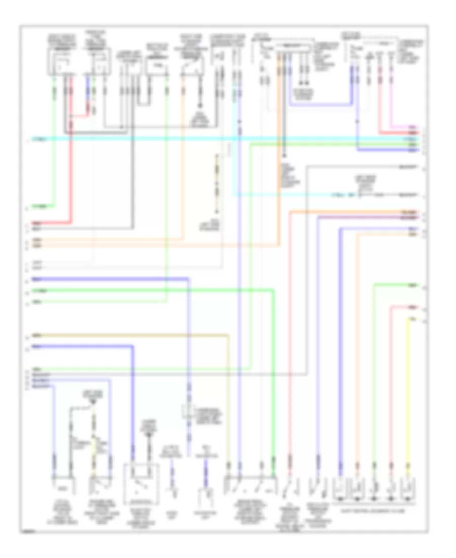
2.4L, Engine Performance Wiring Diagram (3 of 4) for Honda CR-V EX 2008
List of elements for 2.4L, Engine Performance Wiring Diagram (3 of 4) for Honda CR-V EX 2008:
- (bottom of radiator) ect sensor 2
- (left rear of engine compt) j/c c101
- (left side of engine) g101
- (near fuel tank) fuel tank pressure sensor
- (right side of engine compt) a/c pressure sensor
- (right side of engine compt) power steering pressure switch
- (under left side of dash) j/c c404
- (under middle of dash) g503
- (under right side of engine compt) secondary ho2s
- +b horn
- 2nd clutch pressure switch (on transmission housing)
- A13
- A18
- Atp -p
- Atp -r
- Audio unit
- B21
- Brake pedal position switch (under left side of dash, on brake pedal support)
- D3 switch
- D3 switch/ park pin switch (under middle of dash)
- Eld unit
- Ex-l w/ navigation
- F15
- F27
- Fuse 10a
- Fuse 15a
- G101 (left side of engine)
- G13
- G16
- G302 (under left side of of engine compt)
- G401 (under left side of dash)
- Hot at all times
- Hot in on or start
- Lx, ex & ex-l w/o navigation
- Micu
- Navigation unit
- Oil pressure switch (on right front of engine, above oil filter)
- Red
- Rocker arm oil pressure switch (front right side of cylinder head)
- S1 (thermal joint)
- S2 (ther- mal joint)
- Shift control solenoid valves
- Starting/ charging system
- Under-dash fuse/relay box (under left side of dash)
- Under-dash junction box (under left side of dash)
- Under-hood fuse/relay box (on left side of engine compt)
- Vsp
- Vtc oil control solenoid valve (front of cylinder head)
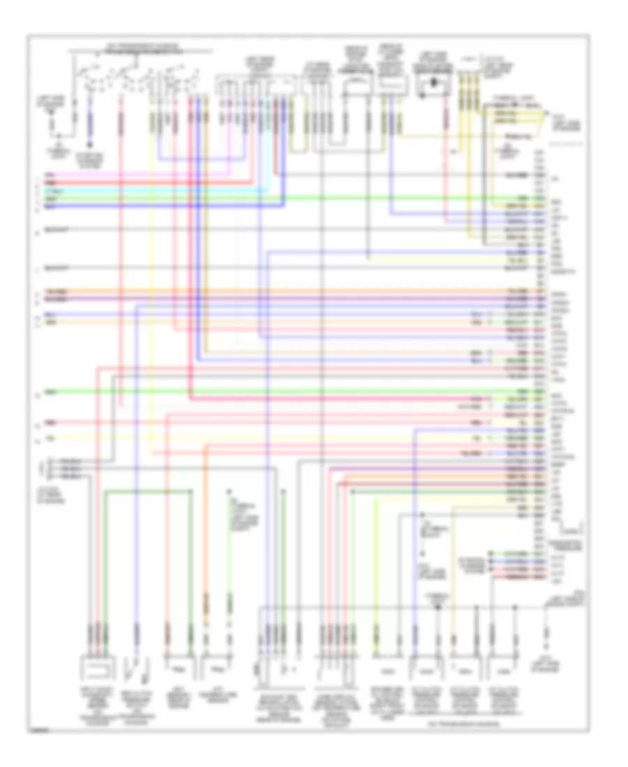
2.4L, Engine Performance Wiring Diagram (4 of 4) for Honda CR-V EX 2008
List of elements for 2.4L, Engine Performance Wiring Diagram (4 of 4) for Honda CR-V EX 2008:
- (at rear of engine) j/c c103
- (left rear of engine compt) j/c c101
- (left side of engine) g101
- (left side of engine, near starter) knock sensor
- (on transmission housing)
- (on transmission housing) transmission range switch
- (rear of cylinder head)
- (rear of engine) evap canister purge valve
- (thermal joint) s3
- 3rd clutch pressure switch (on transmission housing)
- A/t clutch pressure control solenoid valve a
- A/t clutch pressure control solenoid valve b
- A/t clutch pressure control solenoid valve c
- A17
- A22
- Altc
- Altf
- Altl
- Atf temperature sensor
- Atft
- Atp-1
- Atp-2
- Atp-d
- Atp-fwd
- Atp-n
- Atp-p
- Atp-r
- Atp-rvs
- B10
- B11
- B12
- B13
- B14
- B15
- B16
- B17
- B18
- B19
- B20
- B21
- B22
- B23
- B24
- B25
- B26
- B27
- B28
- B29
- B30
- B31
- B32
- B33
- B34
- B35
- B36
- B37
- B38
- B39
- B40
- B41
- B42
- B43
- B44
- Baro
- Barometric pressure
- C33
- C34
- C35
- C36
- C37
- C38
- C39
- C40
- C41
- C42
- C43
- C44
- Camshaft position sensor a
- Cmp a
- Ect sensor 1 (rear of engine)
- Ect1
- Egr
- Egrp
- Exhaust gas recirculation valve & position sensor (rear of engine)
- G101 (left side of engine)
- Iat
- Ig1
- Input shaft (mainshaft) speed sensor (on transmission housing)
- J/c c101 (left rear of engine compt)
- J/c c103 (at rear of engine)
- Lg1
- Lg2
- Lsa
- Lsb
- Lsc
- Mass airflow sensor/ intake air temperature sensor (on intake air duct)
- Op2sw
- Op3sw
- Opsw
- Pcm (left side of engine compt)
- Pcs
- Pg1
- Pg2
- Pnk
- Red
- Rocker arm oil control solenoid (right front of cylinder head)
- S2 (thermal joint)
- S3 (thermal joint)
- S4 (thermal joint) (left side of engine compt)
- Sg2
- Sg3
- Sha
- Shb
- Shc
- Shd
- She
- So2shtc
- Starting/ charging system
- Vcc2
- Vg+
- Vg-
- Vts