ENGINE PERFORMANCE
2.4L
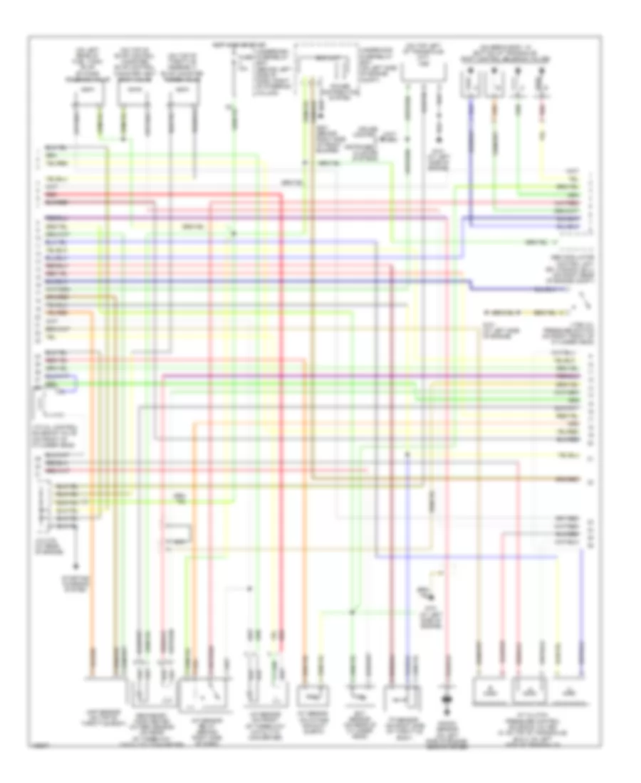
2.4L, Engine Performance Wiring Diagram (1 of 3) for Honda CR-V LX 2004

List of elements for 2.4L, Engine Performance Wiring Diagram (1 of 3) for Honda CR-V LX 2004:
- (at left side of engine)
- (at left side of engine) g101
- (behind right side of dash) pgm-fi main relay 1
- (behind right side of dash) pgm-fi main relay 2
- (in top of fuel tank) fuel tank unit
- (on imrc valve, on top left side of engine) imrc valve position sensor
- (on rear of cylinder head) cmp sensor
- A10
- A11
- A12
- A13
- A14
- A15
- A16
- A17
- A18
- A19
- A20
- A21
- A22
- A23
- A24
- A25
- A26
- A27
- A28
- A29
- A30
- A31
- Afs (+)
- Afs (-)
- Afshtc
- Afshtc (+)
- Altc
- Altf
- Altl
- Atpn
- Atpp
- Atpr
- B10
- B11
- B12
- B13
- B14
- B15
- B16
- B17
- B18
- B19
- B20
- B21
- B22
- B23
- B24
- Barometer pressure sensor
- Ckp
- Ckp sensor (on lower left front of engine, near crankshaft pulley)
- Cmp
- Cooling fans system
- Ecm/pcm (behind right side of dash)
- Ect
- Fanc
- Fuel injectors (on top of engine)
- Fuel pump
- Fuse 15a
- G101
- G101 (at left side of engine)
- G551 (under driver's seat)
- Hot at all times
- Hot in on or start
- Iac valve (on lower left side of throttle assembly)
- Iacv
- Iat
- Icm
- Ignition coils (on top of engine)
- Igp1
- Igp2
- Igpls1
- Igpls2
- Igpls3
- Igpls4
- Immobilizer control unit receiver (on steering column, integral to ignition switch)
- Imrc
- Imrc solenoid valve (on upper left front side of engine)
- Imrc vps
- Inj1
- Inj2
- Inj3
- Inj4
- J/c c103 (at rear of engine)
- Lg1
- Lg2
- Lsa+
- Lsb+
- Lsc (+)
- Map
- Odsw
- Pcs
- Pg1
- Pg2
- Red
- Sg1
- Sg2
- Starting/ charging system
- Tdc
- Tdc sensor (on rear of cylinder head)
- Tps
- Underdash fuse/relay box (behind left side of dash, right of steering column)
- Underhood fuse/relay box (on left side of engine compt)
- Vcc1
- Vcc2
- Vss
- Vtc (+)
- Vtc (-)
- Vtec solenoid valve (on right front of cylinder head)
- Vtpsw
- Vts
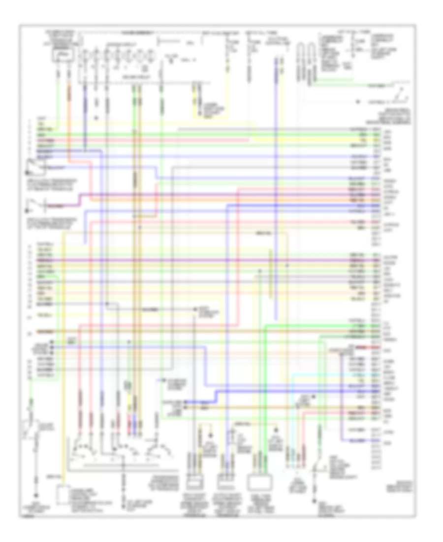
2.4L, Engine Performance Wiring Diagram (2 of 3) for Honda CR-V LX 2004
List of elements for 2.4L, Engine Performance Wiring Diagram (2 of 3) for Honda CR-V LX 2004:
- (on left rear of fuel tank) evap by-pass solenoid valve
- (on servo body, in bottom of transaxle) shift control solenoid valves
- (on top left of transaxle) (m/t) vss
- (on top of evap control canister) evap control canister vent shut valve
- (on top of throttle assembly) evap canister purge valve
- A/f sensor (on front of three-way catalytic converter)
- A/f sensor relay (behind right side of dash)
- A/t clutch pressure control solenoid valves (a: on top of transaxle) (b & c: on left side of transaxle)
- Abs modulator control unit (ex; canada: ex-l) (on right rear of engine compt)
- Cruise control & instrument cluster systems
- Ect sensor (on rear of cylinder head)
- Eld unit
- Fuse 10a
- G101 (at left side of engine)
- G201 (behind right side of front bumper)
- Hot in on or start
- Iat sensor (on intake air duct elbow)
- J/c c103 (at rear of engine)
- Knock sensor (on left side of engine, near starter)
- Map sensor (on top of throttle body)
- Nca
- Power distribution system
- Red
- Secondary ho2s heated oxygen sensor (on rear of three-way catalytic converter)
- Starting/ charging system
- Tp sensor (on right side of throttle body)
- Underdash fuse/relay box (behind left side of dash, right of steering column)
- Underhood fuse/relay box (on left side of engine compt)
- Vtc oil control solenoid valve (on front of cylinder head)
- Vtec oil pressure switch (on right front of cylinder head)
2.4L, Engine Performance Wiring Diagram (3 of 3) for Honda CR-V LX 2004
List of elements for 2.4L, Engine Performance Wiring Diagram (3 of 3) for Honda CR-V LX 2004:
- (at left side of engine) g101
- (on left side of engine compt)
- (on servo body, in bottom of transaxle) atf temperature sensor
- (under right side of dash) g502
- 2nd clutch transmission fluid pressure switch (at top of transaxle)
- 2wbs
- 3rd clutch transmission fluid pressure switch (at rear of transaxle)
- A14
- A16
- A18
- Acc
- Afshtcr
- Air conditioning system
- Anti- theft system
- Atft
- Atp1
- Atp2
- Atpd
- Atpfwd
- Atprvs
- B20
- Bksw
- Brake pedal position switch (behind dash, on brake pedal support)
- C10
- C11
- C12
- C13
- C14
- C15
- C16
- C17
- C18
- C19
- C20
- C21
- C22
- Ccs
- Computer data lines system
- Cpu
- Cruise control system
- D10
- D11
- D12
- D13
- D14
- D15
- D16
- D17
- Dimming circuit
- Dlc (under left side of dash)
- Driver circuit
- E10
- E11
- E12
- E13
- E14
- E15
- E16
- E17
- E18
- E19
- E20
- E21
- E22
- E23
- E24
- E25
- E26
- E27
- E28
- E29
- E30
- E31
- Ecm/pcm (behind right side of dash)
- Eld
- Ftp
- Fuel tank pressure sensor (on left rear of fuel tank)
- Fuse 15a
- Fuse 20a
- Fuse 7.5a
- Fuse/relay box
- G101 (at left side of engine)
- G301 (behind left side of front bumper)
- G451 (under middle of dash)
- Gauge assembly
- Hot at all times
- Hot in on or start
- Ig1
- Ilu
- Immobilizer control unit receiver (on steering column, integral to ignition switch)
- Imo fpr
- Imocd
- Input shaft (mainshaft) speed sensor (on rear right side of transaxle)
- J/c c103 (at rear of engine)
- K-line
- Lg3
- Lsa-
- Lsb-
- Lsc (-)
- Mil
- Mil ind
- Mrly
- Multiplex control unit
- Nep
- O/d off
- O/d off switch
- Op2sw
- Op3sw
- Output shaft (countershaft) speed sensor (on front right side of transaxle)
- Pnk
- Psp switch (on lower center rear of engine compt)
- Pspsw
- Red
- Scs
- Sefmj
- Sg3
- Sha
- Shb
- Shc
- She
- Shift interlock system
- Sho2s
- So2shtc
- Starting/ charging system
- Transmission range switch (on lower rear of transaxle)
- Underdash fuse/relay box (behind left side of dash, right of steering column)
- Underhood
- Vcc3
- Vssout
- Vsv
- Wen