ENGINE PERFORMANCE
Engine Performance Wiring Diagram (1 of 6) for Honda Odyssey EX 2006

List of elements for Engine Performance Wiring Diagram (1 of 6) for Honda Odyssey EX 2006:
Engine Performance Wiring Diagram (2 of 6) for Honda Odyssey EX 2006
List of elements for Engine Performance Wiring Diagram (2 of 6) for Honda Odyssey EX 2006:
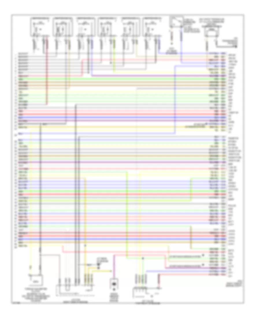
Engine Performance Wiring Diagram (3 of 6) for Honda Odyssey EX 2006
List of elements for Engine Performance Wiring Diagram (3 of 6) for Honda Odyssey EX 2006:
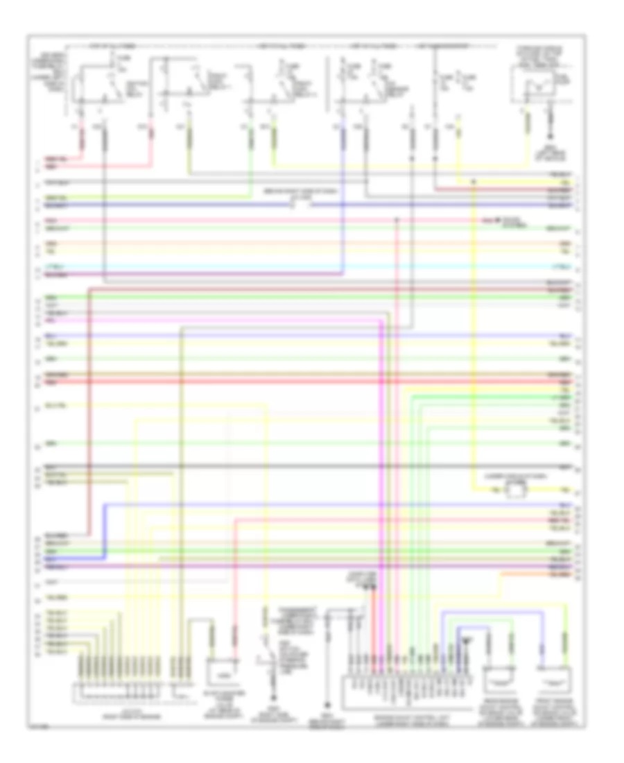
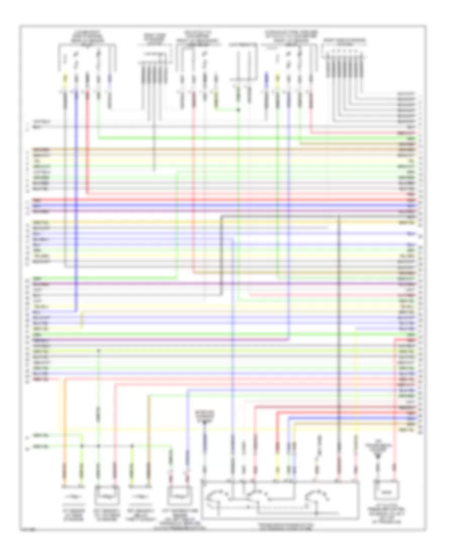
Engine Performance Wiring Diagram (4 of 6) for Honda Odyssey EX 2006
List of elements for Engine Performance Wiring Diagram (4 of 6) for Honda Odyssey EX 2006:
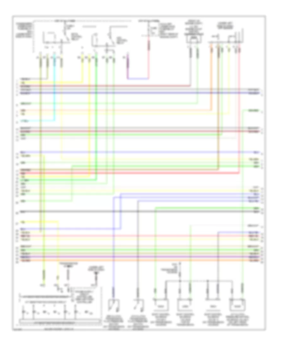
Engine Performance Wiring Diagram (5 of 6) for Honda Odyssey EX 2006
List of elements for Engine Performance Wiring Diagram (5 of 6) for Honda Odyssey EX 2006:
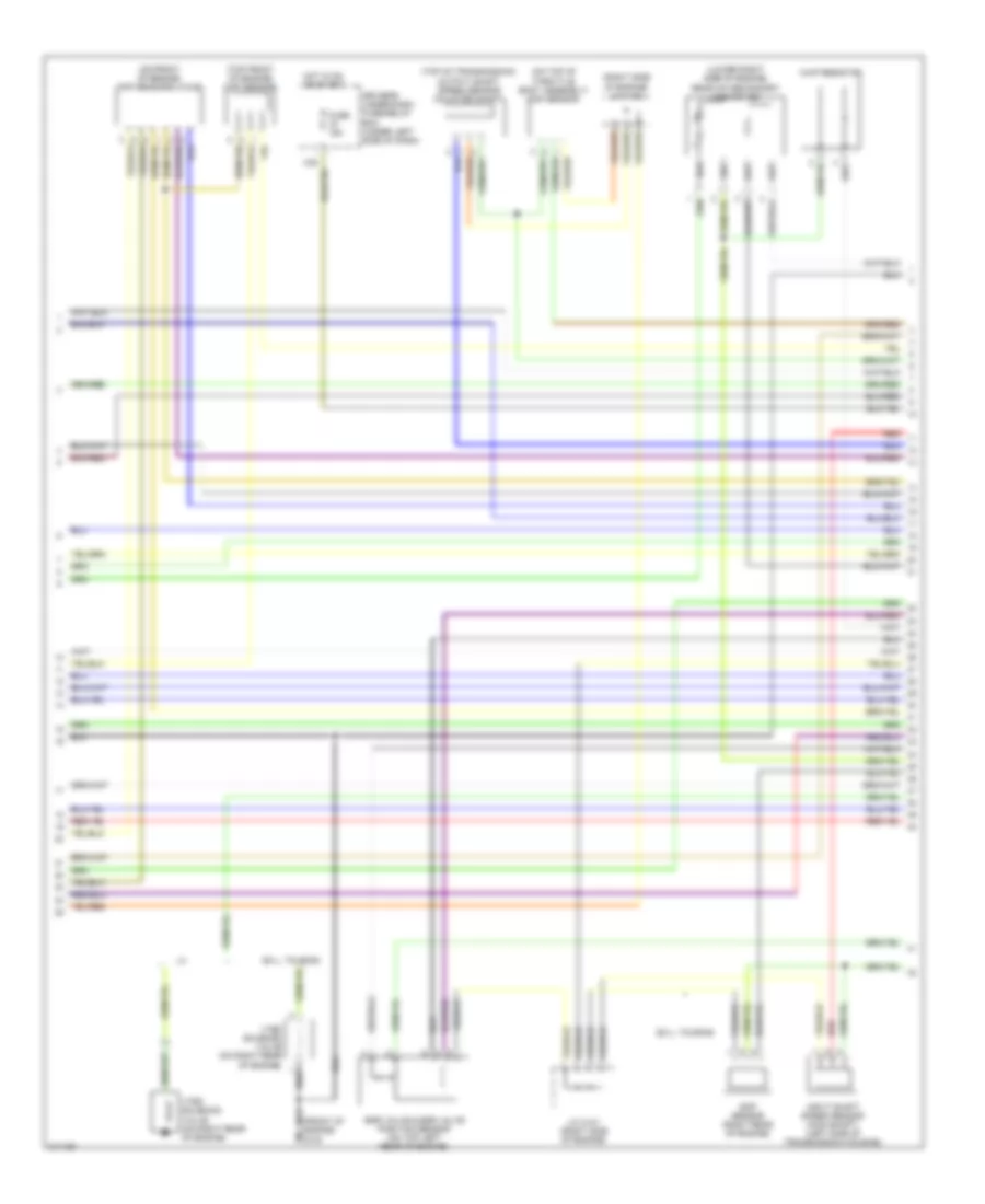
Engine Performance Wiring Diagram (6 of 6) for Honda Odyssey EX 2006
List of elements for Engine Performance Wiring Diagram (6 of 6) for Honda Odyssey EX 2006: