ENGINE PERFORMANCE
3.5L
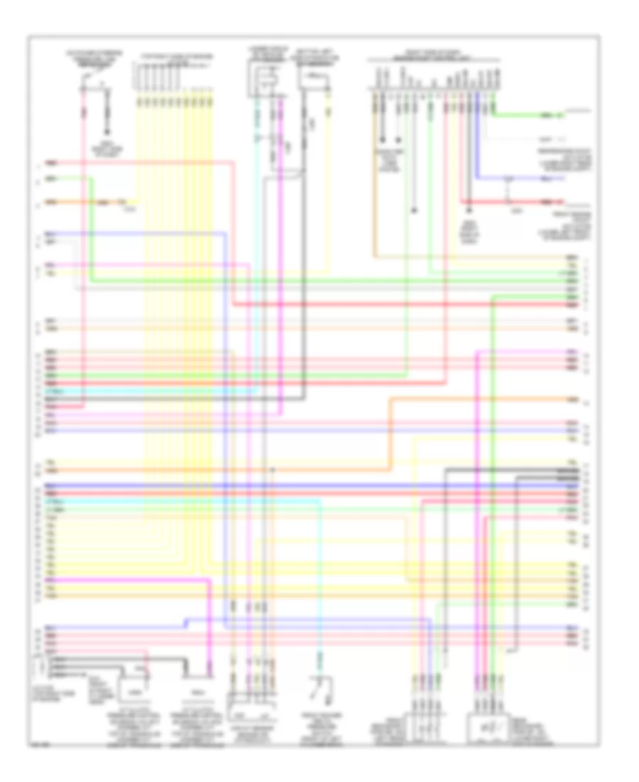
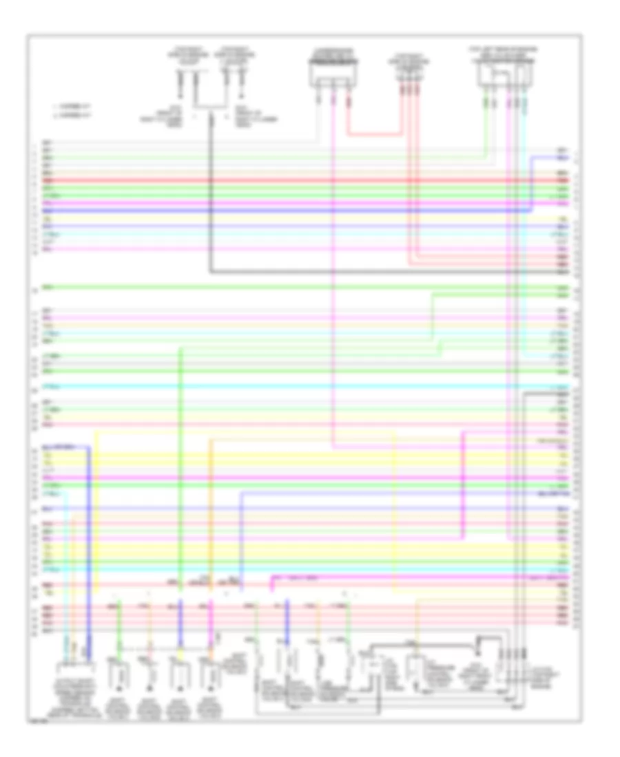
3.5L, Engine Performance Wiring Diagram (1 of 7) for Honda Odyssey Touring 2013

List of elements for 3.5L, Engine Performance Wiring Diagram (1 of 7) for Honda Odyssey Touring 2013:
- (center of dash) g403
- (left side of dash) g302
- (top of accelerator pedal assembly) app sensor
- 5-speed a/t
- 6-speed a/t
- A10
- A11
- A12
- A13
- A14
- A15
- A16
- A17
- A19
- A20
- A21
- A22
- A23
- A24
- A25
- A26
- A27
- A28
- A29
- A30
- A31
- A32
- A33
- A35
- A36
- A37
- A38
- A39
- A40
- A41
- A42
- A43
- A44
- A45
- A46
- A47
- A48
- A49
- Acc
- Air conditioning system
- Anti-theft system
- Apsa
- Apsb
- Atpp d3sw d4sw a18
- B10
- B11
- B12
- B13
- B14
- B15
- B16
- B17
- B18
- B19
- B20
- B21
- Baro- meter sensor
- Bksw
- Bkswnc
- C201
- C210
- C212
- Ckpout
- Cmpout
- Computer data lines system
- Cooling fans system
- Cruise control system
- Cssama
- Cssamc
- D4 switch
- Ect2
- Eld
- Eld unit
- Etcs control relay
- Etcsrly
- F-canh
- F-canl
- Fanh
- Fanl
- Ftp
- Fuse 15a
- G101 (front of right cylinder head)
- Hot at all times
- Hot in on or start
- Igp
- Igpls5
- Igpls6
- Imofpr
- Imtm
- Inj1
- Inj2
- Inj3
- Inj4
- Inj5
- Inj6
- Injector 6 (top of left side of engine)
- Injectors 1, 2 & 3 (top of right side of engine)
- Injectors 4 & 5 (top of left side of engine)
- J/c c105 (top right side of engine)
- Lever conn- etor
- Lg3
- Lsb
- Lsc
- Main under-hood fuse box (left side of engine compt)
- Mcs
- Mrly
- Navigation & sound systems
- Pcm (right rear of engine compt)
- Pg2
- Pgm fi main relay 1
- Pnk
- Power distrib- ution system
- Pspsw
- Red
- S net
- Scs nep (or vssout) a34
- Sensor system
- Sg3
- Sg4
- Sg7
- Shift
- Shift interlock system
- Sho2sb2
- Sls
- Starting/ charging system
- Starting/charging & anti-theft systems
- Starting/charging system
- Strld
- Strly
- Sts
- Sub rly
- Tan
- Tpsa
- Under-hood relay fuse/box (right rear of engine compt)
- Vbsol
- Vbsol2
- Vcc3
- Vcc4
- Vcc5
- Vcc7
- Vcentb1
- Vcmswc
- Vg+
- Vg-
- Vsb1
- Vsb2
- Vssout
- Vsv
- W/ parking & break up
- W/o parking & break up sensor system
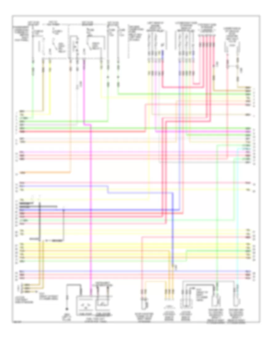
3.5L, Engine Performance Wiring Diagram (2 of 7) for Honda Odyssey Touring 2013
List of elements for 3.5L, Engine Performance Wiring Diagram (2 of 7) for Honda Odyssey Touring 2013:
- (bottom left side of radiator) ect sensor 2
- (on power steering pressure line) psp switch
- (right side of dash) engine mount control unit
- (top right side of engine) j/c c102
- (under middle of vehicle) ftp sensor
- A/t clutch pressure control solenoid valve b (5-speed a/t: top of transaxle) (6-speed a/t: side of transaxle)
- A/t clutch pressure control solenoid valve c (5-speed a/t: top of transaxle) (6-speed a/t: side of transaxle)
- Braided
- C101
- C201
- C207
- C210
- Ckp
- Cmp
- Computer data lines system
- Dash)
- F-can h
- F-can l
- Front engine mount actuator (lower left front of engine compt)
- Front rocker arm oil pressure switch (front of left cylinder bank)
- Front secondary ho2s (b2, s2) (left rear of engine)
- G101 (front of right cylinder head)
- G204 (right side of
- G204 (right side of dash)
- Iat
- Ig1
- Igsol
- J/c c105 (top right side of engine)
- Maf
- Maf/iat sensor (engine air intake duct)
- Pnk
- Rear engine mount actuator (lower right rear of engine compt)
- Rear secondary ho2s (b1, s2) (lower right side of engine)
- Red
- Solfm
- Solfp
- Solrly
- Solrm
- Solrp
- Tan
3.5L, Engine Performance Wiring Diagram (3 of 7) for Honda Odyssey Touring 2013
List of elements for 3.5L, Engine Performance Wiring Diagram (3 of 7) for Honda Odyssey Touring 2013:
- (left rear of engine) front a/f sensor (b2, s1)
- (lower right side of engine) rear a/f sensor (b1, s1)
- (top right side of engine) j/c c104
- (under middle of vehicle) evap canister vent shut valve
- Acm cont- rol relay
- Braided
- C101
- C207
- C210
- Driver's under dash fuse/ relay box (left end of dash)
- E16
- Evap canister purge valve (right rear of engine)
- F10
- F20
- F21
- Fuel gauge sending unit
- Fuel pump
- Fuel tank unit (top of fuel tank)
- Fuse 20 7.5a
- Fuse 20a
- Fuse 3 10a
- Fuse 7.5a
- G101 (front of right cylinder head)
- G602 (left "c" pillar)
- Hot at all times
- Hot in on or start
- Instrument cluster system
- J/c c104 (top right side of engine)
- J/c c105 (top right side of engine)
- Passenger's under-dash fuse/relay (behind right kick panel)
- Pgm-fi main relay 2
- Pnk
- Red
- Rocker arm oil control solenoid a (bank 1) (rear of right cylinder bank)
- Rocker arm oil control solenoid b (bank 1) (rear of right cylinder bank)
- Tan
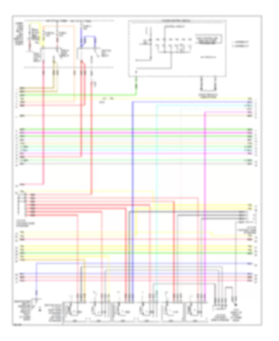
3.5L, Engine Performance Wiring Diagram (4 of 7) for Honda Odyssey Touring 2013
List of elements for 3.5L, Engine Performance Wiring Diagram (4 of 7) for Honda Odyssey Touring 2013:
- 5-speed a/t
- 6-speed a/t
- C101
- C212
- Computer data lines system
- Control circuit
- Fast controller area network transceiver
- Fuse 11 15a
- Fuse 28 7.5a
- Fuse 8 15a
- G101 (front of right cylinder head)
- Gauge control module
- Hot at all times
- Icm
- Ignition coil relay
- Ignition coils (1, 2 & 3: right side of engine) (4, 5 & 6: left side of engine)
- J/c c102 (top right side of engine)
- J/c c104 (top right side of engine)
- J/c c105 (top right side of engine)
- Mil ind
- Pgm fi sub relay
- Pnk
- Radi- ator fan relay
- Radi- ator fan relay diode
- Rear rocker arm oil pressure switch (rear of right cylinder bank)
- Red
- Tan
- Under- hood fuse/ relay box (right rear of engine compt)
3.5L, Engine Performance Wiring Diagram (5 of 7) for Honda Odyssey Touring 2013
List of elements for 3.5L, Engine Performance Wiring Diagram (5 of 7) for Honda Odyssey Touring 2013:
- (5-speed: on transaxle) (6-speed: left side of transaxle) input shaft (mainshaft) speed sensor
- (bottom of transaxle) atf temperature sensor
- (on transaxle) atf temperature sensor
- (top rear of engine) ect sensor 1
- (top right side of engine) j/c c104
- (top right side of engine) j/c c105
- 2nd clutch transmission fluid pressure switch (5-speed: bottom of transaxle) (6-speed: side of transaxle)
- 3rd clutch transmission fluid pressure switch (5-speed: on transaxle) (6-speed: top of transaxle)
- 5-speed a/t
- 6-speed a/t
- C101
- J/c c105 (top right side of engine)
- Maf sensor (top rear of engine)
- Pnk
- Red
- Starting/ charging system
- Tan
- Transmission range switch (5-speed a/t: left side of transaxle) (6-speed a/t: top of transaxle)
3.5L, Engine Performance Wiring Diagram (6 of 7) for Honda Odyssey Touring 2013
List of elements for 3.5L, Engine Performance Wiring Diagram (6 of 7) for Honda Odyssey Touring 2013:
- (top left rear of engine) egr valve & egr valve position sensor
- (top right side of engine) j/c c102
- (top right side of engine) j/c c103
- (top right side of engine) j/c c105
- (under engine) rocker arm oil pressure sensor
- 5-speed a/t
- 6-speed a/t
- A/t pressure control solenoid valve d
- C107
- G101 (front of right cylinder head)
- G101 (front of right front cylinder head)
- J/c c102 (top right side of engine)
- J/c c105 (top right side of eng)
- Line pressure solenoid valve
- Output shaft (countershaft) speed sensor (5-speed: on transaxle) (6-speed: bottom rear of transaxle)
- Pnk
- Red
- Shift control solenoid valve a
- Shift control solenoid valve b
- Shift control solenoid valve c
- Shift control solenoid valve d
- Tan
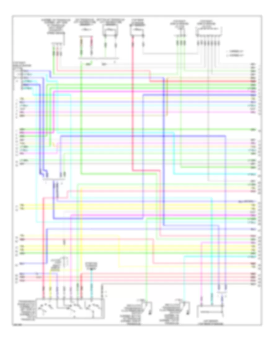
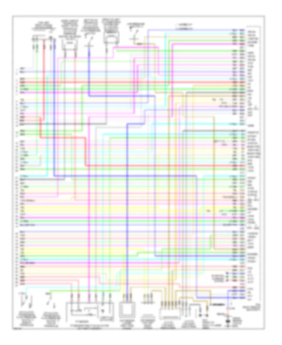
3.5L, Engine Performance Wiring Diagram (7 of 7) for Honda Odyssey Touring 2013
List of elements for 3.5L, Engine Performance Wiring Diagram (7 of 7) for Honda Odyssey Touring 2013:
- (6-spd: side of transaxle) (5-spd: top of transaxle) a/t clutch pressure control solenoid valve a
- (bottom of transaxle) 4th clutch transmission fluid pressure switch
- (front of left cylinder bank) rocker arm oil control solenoid a (bank 2)
- (top left front of eng) imt actuator
- 5-speed a/t
- 5th clutch transmission fluid pressure switch (side of transaxle)
- 6-speed a/t
- 6th clutch transmission fluid pressure switch (top of transaxle)
- Afshtcb1
- Afshtcb2
- Altc
- Altf
- Altl
- Atpd
- Atpfwd
- Atpl
- Atpn
- Atpr
- Atprvs
- B22
- B23
- B24
- B25
- B26
- B27
- B28
- B29
- B30
- B31
- B32
- B33
- B34
- B35
- B36
- B37
- B38
- B39
- B40
- B41
- B42
- B43
- B44
- B45
- B46
- B47
- B48
- B49
- Braided
- C10
- C101
- C106
- C11
- C12
- C13
- C14
- C15
- C16
- C17
- C18
- C19
- C20
- C21
- C22
- C23
- C24
- C25
- C26
- C27
- C28
- C29
- C30
- C31
- C32
- C33
- C34
- C35
- C36
- C37
- C38
- C39
- C40
- C41
- C42
- C43
- C44
- C45
- C46
- C47
- C48
- C49
- Ckp
- Ckp sensor (lower right side of eng)
- Cmp
- Cmp sensor (top left front of eng)
- Cssa
- Cssb
- Cssc
- Ect1
- Egr
- Egrp
- Etcsm+
- Etcsm-
- G101 (front of right cylinder head)
- Iat
- Ig1
- Ig1etcs
- Igpls1
- Igpls2
- Igpls3
- Igpls4
- Imt+
- Imt-
- Ip b1
- Ip b2
- J/c c102 (top right side of eng)
- J/c c103 (top right side of eng)
- Knock sensor (top of eng)
- Lg1
- Lg2
- Line pressure switch
- Lsd
- Map
- Op2sw
- Op3sw
- Op4sw
- Op6sw
- Pcm (right rear of eng compt)
- Pcs
- Pg1
- Pgmetcs
- Pla
- Pnk
- Poil
- Red
- Sg1
- Sg2
- Sg5
- Sg6
- Sha
- Shb
- Shb lsa
- Shc
- Shd
- Sho2sb1
- So2sgb1
- So2sgb2
- So2shtcb1
- So2shtcb2
- Starting/ charging system
- Tan
- Tatf
- Throttle actuator
- Tp sensor
- Tp sensor/throttle actuator (on throttle body)
- Tpsb
- Vcc1
- Vcc2
- Vcc6
- Vcentb2
- Vcmswb