ENGINE PERFORMANCE
3.5L
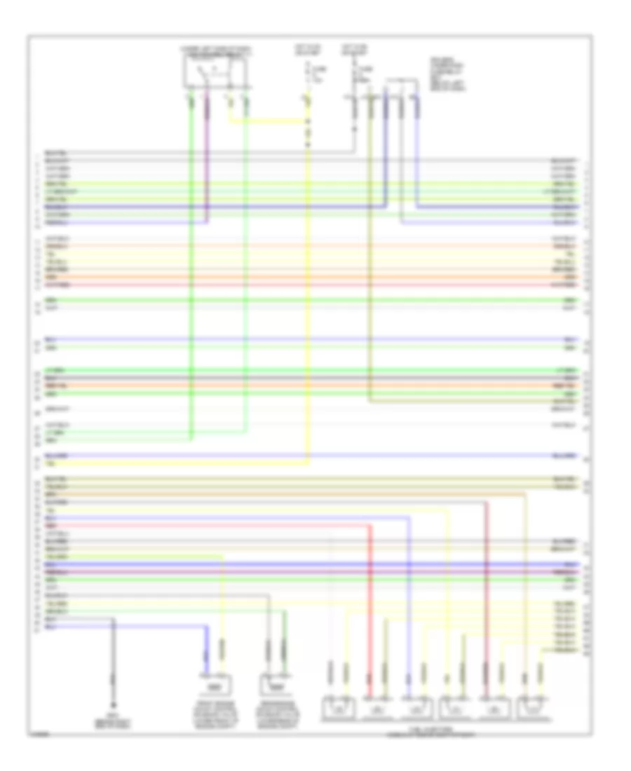
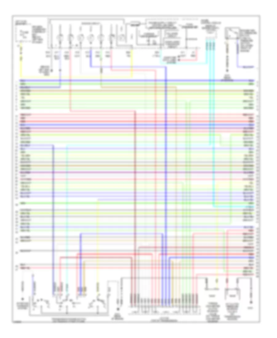
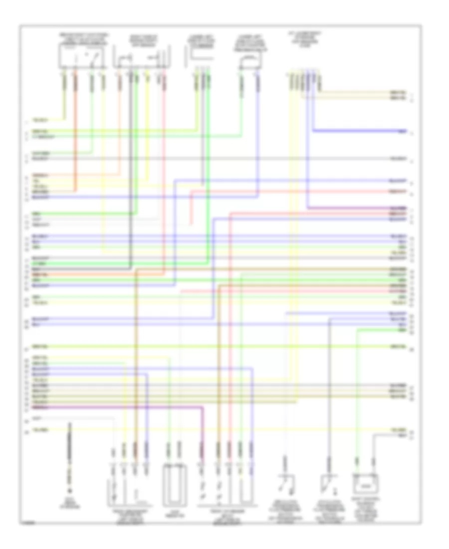
3.5L, Engine Performance Wiring Diagram, 2WD (1 of 7) for Honda Pilot LX 2006

List of elements for 3.5L, Engine Performance Wiring Diagram, 2WD (1 of 7) for Honda Pilot LX 2006:
- (at top of brake pedal arm) brake pedal position switch
- A10
- A11
- A12
- A13
- A14
- A15
- A16
- A17
- A18
- A19
- A20
- A21
- A22
- A23
- A24
- A25
- A26
- A27
- A28
- A29
- A30
- A31
- A32
- A33
- A34
- A35
- A36
- A37
- A38
- A39
- A40
- A41
- A42
- A43
- A44
- Acc
- Acs
- Active noise control unit (behind middle of dash)
- Afshtcr
- Air conditioning system
- Anti-theft system
- Apsa
- Apsb
- Atp-p
- Auxiliary fuse box (at left side of engine compt)
- B10
- B11
- B12
- B13
- B14
- B15
- B16
- B17
- B18
- B19
- Barometer sensor
- Bksw
- Bkswnc
- Braided wire
- Can-h
- Can-l
- Ckpout
- Cmpout
- Computer data lines system
- Crk 1
- Cruise control system
- Cssam
- Cyl
- Eld
- Engine mount control unit (right side of center console)
- Etcsrly
- Fanh
- Fanl
- Ftp
- Fuse 10a
- Fuse 15a
- G101 (rear of engine)
- G501
- G505
- Hot at all times
- Ig1
- Igp
- Igpls5
- Igpls6
- Igsol1
- Igsol2
- Imo fpr
- Imocd
- Inj1
- Inj2
- Inj3
- Inj4
- Inj5
- Inj6
- J/c c306 (behind left side of dash)
- K-line
- Lg3
- Mrly
- Nep
- Pg1
- Pg2
- Pnk
- Powertrain control module (pcm) (right side of engine compt)
- Pspsw
- Red
- Scp
- Scs
- Sg3
- Sg4
- Sg7
- Shift interlock system
- Sho2s b1
- Sho2s b2
- Sls
- Solfm
- Solfp
- Solrly
- Solrm
- Solrp
- Starting/charging system
- Tp sensor/ throttle actuator (on side of throttle body assembly)
- Tpsa
- Tpsb
- Transmissions system
- Under-hood fuse/relay box (at right side of engine compt)
- Vbsol
- Vcc1
- Vcc3
- Vcc4
- Vcc5
- Vcc7
- Vs b1
- Vs b2
- Vssout
- Vsv
- Wen
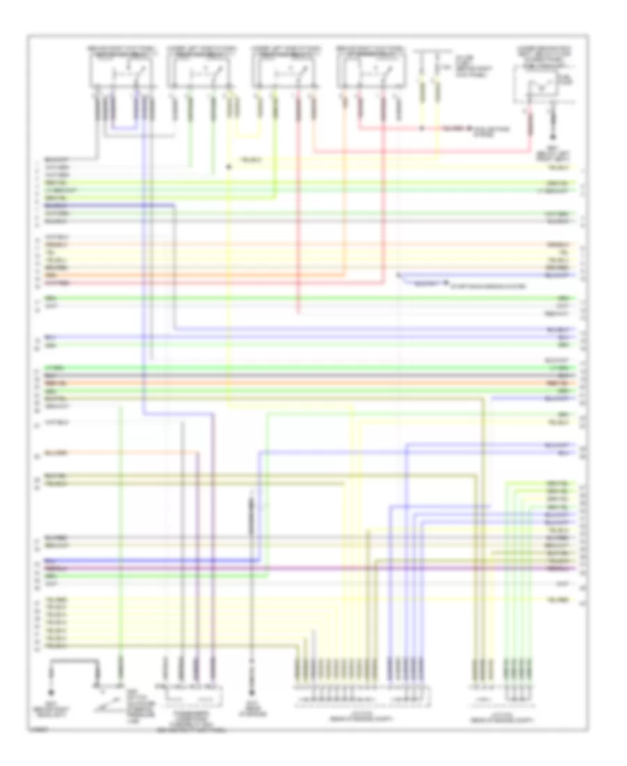
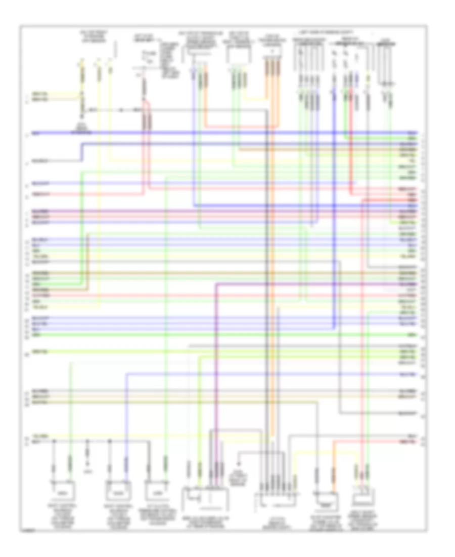
3.5L, Engine Performance Wiring Diagram, 2WD (2 of 7) for Honda Pilot LX 2006
List of elements for 3.5L, Engine Performance Wiring Diagram, 2WD (2 of 7) for Honda Pilot LX 2006:
- (under left side of dash) acm control relay
- Driver's under-dash fuse/relay box (below left end of dash)
- Front engine mount control solenoid valve (lower front of engine compt)
- Fuel injectors (middle of engine compartment)
- Fuse 10a
- Fuse 15a
- G503 (behind right end of dash)
- Hot in on or start
- Rear engine mount control solenoid valve (lower rear of engine compt)
- Red
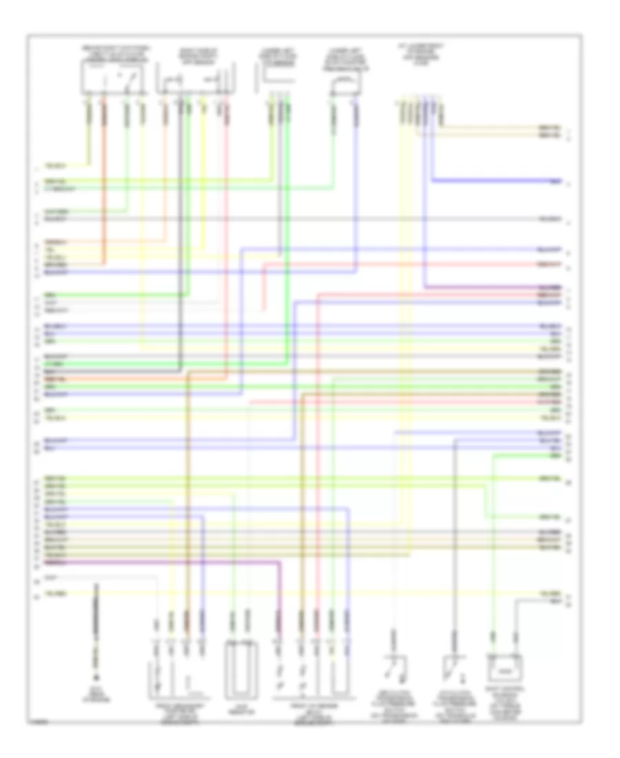
3.5L, Engine Performance Wiring Diagram, 2WD (3 of 7) for Honda Pilot LX 2006
List of elements for 3.5L, Engine Performance Wiring Diagram, 2WD (3 of 7) for Honda Pilot LX 2006:
- (behind right kick panel) a/f sensor relay
- (behind right kick panel) ignition coil relay
- (under left side of dash) pgm-fi main relay 1
- (under left side of dash) pgm-fi main relay 2
- (under second row seat, below floor access panel) fuel tank unit
- 7.5a
- Braided wire
- Cooling fans system
- Fuel pump
- G101 (rear of engine)
- G201 (behind right headlight)
- G601 (below left front seat)
- In-line fuse 1 (behind right kick panel)
- J/c c103 (rear of engine compt)
- J/c c104 (rear of engine compt)
- Passenger's under-dash fuse/relay box (behind right kick panel)
- Psp switch (on power steering pressure line)
- Starting/charging system
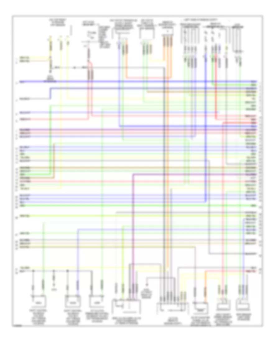
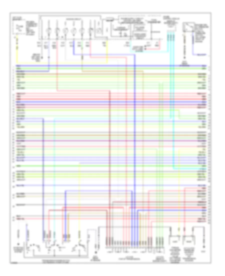
3.5L, Engine Performance Wiring Diagram, 2WD (4 of 7) for Honda Pilot LX 2006
List of elements for 3.5L, Engine Performance Wiring Diagram, 2WD (4 of 7) for Honda Pilot LX 2006:
- (at lower front of engine) ckp sensors (a & b)
- (behind right kick panel) throttle actuator control module relay
- (right side of engine compt) app sensor
- (under left side of floor) evap canister vent shut valve
- (under left side of floor) ftp sensor
- 3rd clutch transmission fluid pressure switch (on transmission housing)
- 4th clutch transmission fluid pressure switch (on transaxle end cover)
- Braided wire
- Chip resistor
- Front a/f sensor (b2 s1) (left side of engine compt)
- Front secondary ho2s (b2 s2) (left side of engine compt)
- G101 (rear of engine)
- Shift control solenoid valve c (on torque converter housing)
3.5L, Engine Performance Wiring Diagram, 2WD (5 of 7) for Honda Pilot LX 2006
List of elements for 3.5L, Engine Performance Wiring Diagram, 2WD (5 of 7) for Honda Pilot LX 2006:
- (left side of engine compt)
- (on top front of engine) cmp sensor
- (on top of throttle body assembly) map sensor
- (on top of transaxle) output shaft speed sensor (counter shaft)
- (rear of engine compt) j/c c104
- A/t clutch pressure control solenoid valve c (on transmission housing)
- Chip resistor
- Driver's under- dash fuse/ relay box (below left end of dash)
- Egr valve & egr valve position sensor (at rear of engine)
- Eop sensor (left side of engine)
- Evap canister purge valve (on top rear of intake manifold)
- Fuse 15a
- G101 (rear of engine)
- G102 (at right front of engine)
- G151
- Hot in on or start
- Input shaft speed sensor (mainshaft) (on transaxle end cover)
- J/c c104 (rear of engine compt)
- Rear a/f sensor (b1 s1)
- Rear secondary ho2s (b1 s2)
- Red
- Shift control solenoid valve a (on torque converter housing)
- Shift control solenoid valve b (on torque converter housing)
3.5L, Engine Performance Wiring Diagram, 2WD (6 of 7) for Honda Pilot LX 2006
List of elements for 3.5L, Engine Performance Wiring Diagram, 2WD (6 of 7) for Honda Pilot LX 2006:
- (behind left end of dash) g502
- (rear of engine compt) j/c c104
- A/t clutch pressure solenoid valve a (on transmission housing)
- A11
- A12
- A13
- A14
- A15
- A16
- A17
- B18
- B25
- B33
- Compulsory turning-off circuit
- Computer data lines system
- Dimming circuit
- Driver
- Driver's underdash fuse/relay box (below left end of dash)
- F-can transceiver
- Fail-safe circuit
- Fuse 10a
- G101 (rear of engine)
- G151
- Gauge control module
- Hot in on or start
- J/c c105 (top of transmission)
- Mil ind
- Red
- Rocker arm oil pressure switch (vtec oil pressure switch) (on lower front of engine)
- Starting/ charging system
- Torque converter clutch solenoid valve (on torque converter housing)
- Transmission range switch (on transaxle end cover)
- Warning drive circuit
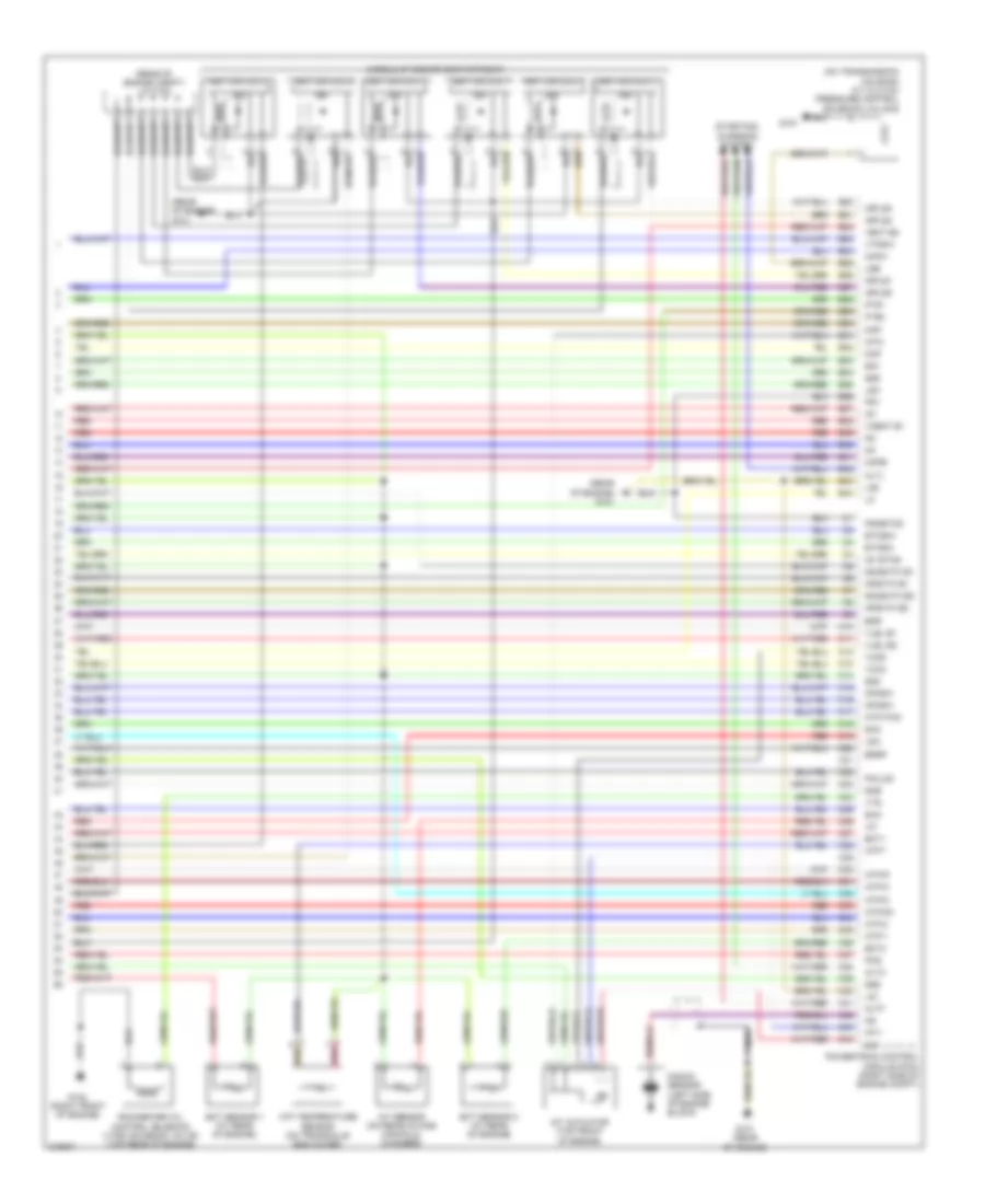
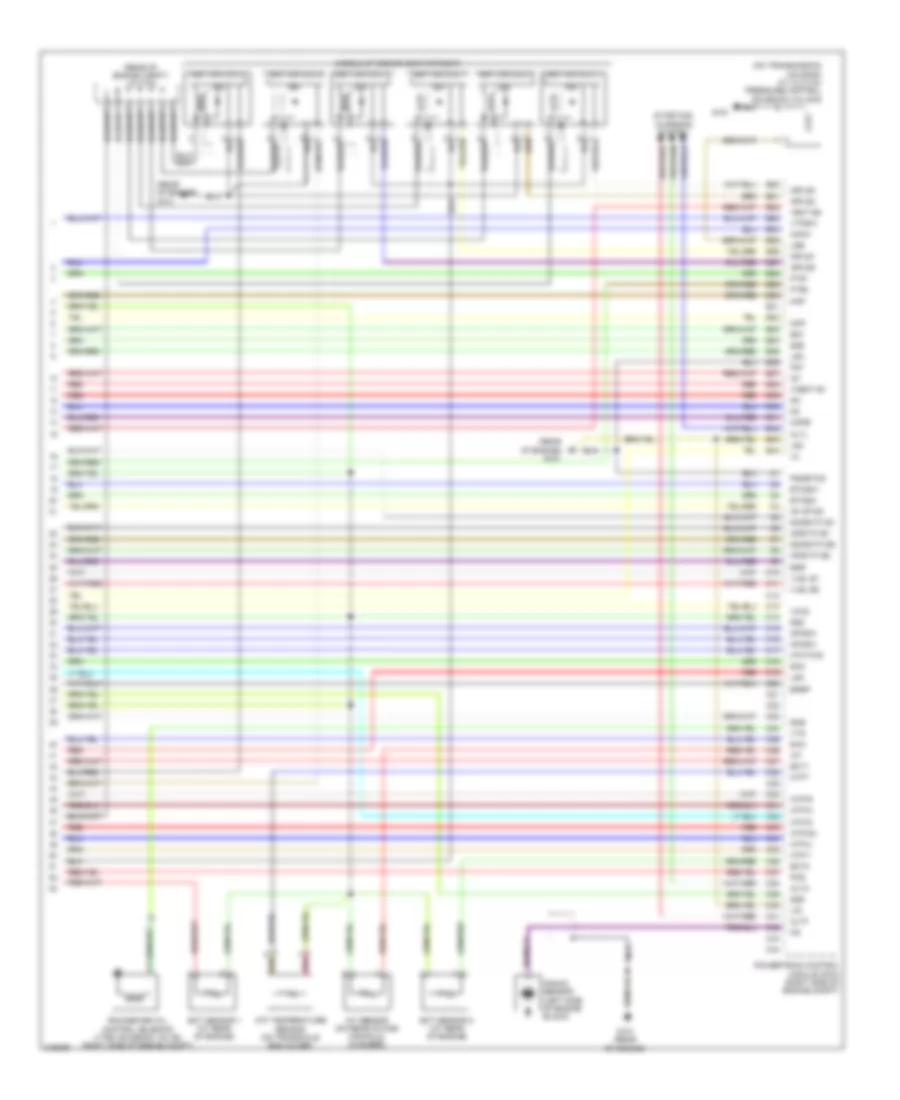
3.5L, Engine Performance Wiring Diagram, 2WD (7 of 7) for Honda Pilot LX 2006
List of elements for 3.5L, Engine Performance Wiring Diagram, 2WD (7 of 7) for Honda Pilot LX 2006:
- (middle of engine compartment)
- (on transmission housing) a/t clutch pressure control solenoid valve b
- (rear of engine compt) j/c c103
- (rear of engine) g101
- Afshtc b1
- Afshtc b2
- Altc
- Altf
- Altl
- Atf temperature sensor (on transaxle end cover)
- Atft
- Atp fwd
- Atp-1
- Atp-2
- Atp-d
- Atp-d3
- Atp-n
- Atp-r
- B20
- B21
- B22
- B23
- B24
- B25
- B26
- B27
- B28
- B29
- B30
- B31
- B32
- B33
- B34
- B35
- B36
- B37
- B38
- B39
- B40
- B41
- B42
- B43
- B44
- C10
- C11
- C12
- C13
- C14
- C15
- C16
- C17
- C18
- C19
- C20
- C21
- C22
- C23
- C24
- C25
- C26
- C27
- C28
- C29
- C30
- C31
- C32
- C33
- C34
- C35
- C36
- C37
- C38
- C39
- C40
- C41
- C42
- C43
- C44
- Ckpa
- Ckpb
- Cmp
- Ect sensor 1 (at rear of engine)
- Ect sensor 2 (at rear of engine)
- Ect1
- Ect2
- Egr
- Egrp
- Etcsm+
- Etcsm-
- G101 (rear of engine)
- G102 (right front of engine)
- G151
- Iat
- Iat sensor (on rear intake manifold chamber)
- Icm
- Ig1
- Ig1 etcs
- Ignition coil 1
- Ignition coil 2
- Ignition coil 3
- Ignition coil 4
- Ignition coil 5
- Ignition coil 6
- Igpls1
- Igpls2
- Igpls3
- Igpls4
- Imt actuator (top front of engine)
- Imt+
- Imt-
- Imtm
- Ip b1
- Ip b2
- Knock sensor (left side of engine block)
- Lg1
- Lg2
- Lsa
- Lsb
- Lsc
- Map
- Nca
- Op3sw
- Op4sw
- Pcs
- Pg1
- Pgmetcs
- Pnk
- Poilcs
- Powertrain control module (pcm) (right side of engine compt)
- Red
- Rocker arm oil control solenoid (vtec solenoid valve) (top rear of engine)
- Sg1
- Sg2
- Sg5
- Sg6
- Sha
- Shb
- Shc
- So2shtc b1
- So2shtc b2
- Starting/ charging system
- Vcc2
- Vcc6
- Vcent b1
- Vect b2
- Vlbl b1
- Vlbl b2
- Vtpsw
- Vts
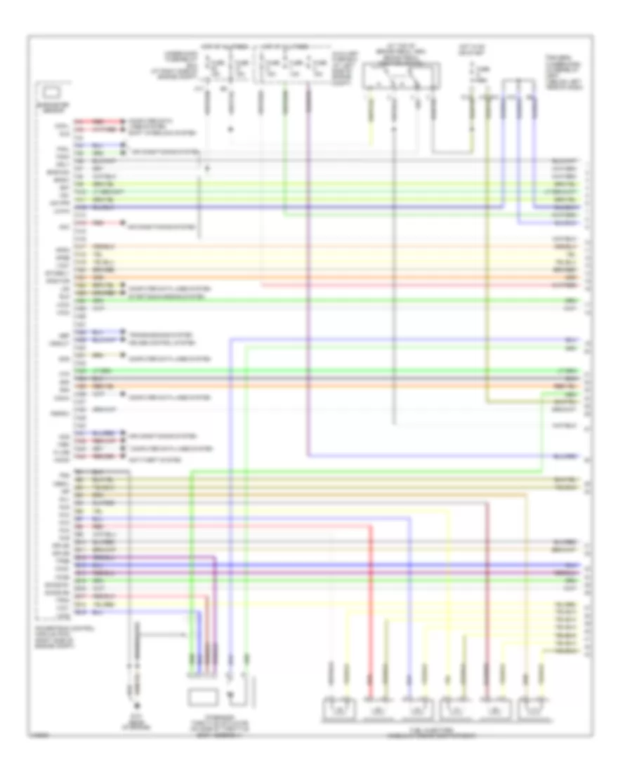
3.5L, Engine Performance Wiring Diagram, 4WD (1 of 6) for Honda Pilot LX 2006
List of elements for 3.5L, Engine Performance Wiring Diagram, 4WD (1 of 6) for Honda Pilot LX 2006:
- (at top of brake pedal arm) brake pedal position switch
- A10
- A11
- A12
- A13
- A14
- A15
- A16
- A17
- A18
- A19
- A20
- A21
- A22
- A23
- A24
- A25
- A26
- A27
- A28
- A29
- A30
- A31
- A32
- A33
- A34
- A35
- A36
- A37
- A38
- A39
- A40
- A41
- A42
- A43
- A44
- Acc
- Acs
- Afshtcr
- Air conditioning system
- Anti-theft system
- Apsa
- Apsb
- Atp-p
- Auxiliary fuse box (at left side of engine compt)
- B10
- B11
- B12
- B13
- B14
- B15
- B16
- B17
- B18
- B19
- Barometer sensor
- Bksw
- Bkswnc
- Braided wire
- Can-h
- Can-l
- Computer data lines system
- Cruise control system
- Driver's under-dash fuse/relay box (below left end of dash)
- Eld
- Etcsrly
- Fanh
- Fanl
- Ftp
- Fuel injectors (middle of engine compartment)
- Fuse 15a
- G101 (rear of engine)
- Hot at all times
- Hot in on or start
- Igp
- Igpls5
- Igpls6
- Imo fpr
- Imocd
- Inj1
- Inj2
- Inj3
- Inj4
- Inj5
- Inj6
- K-line
- Lg3
- Mrly
- Nep
- Pg2
- Powertrain control module (pcm) (right side of engine compt)
- Pspsw
- Red
- Scs
- Sg3
- Sg4
- Sg7
- Shift interlock system
- Sho2s b1
- Sho2s b2
- Sls
- Starting/charging system
- Tp sensor/ throttle actuator (on side of throttle body assembly)
- Tpsa
- Tpsb
- Transmissions system
- Under-hood fuse/relay box (at right side of engine compt)
- Vbsol
- Vcc1
- Vcc3
- Vcc4
- Vcc5
- Vcc7
- Vs b1
- Vs b2
- Vssout
- Vsv
- Wen
3.5L, Engine Performance Wiring Diagram, 4WD (2 of 6) for Honda Pilot LX 2006
List of elements for 3.5L, Engine Performance Wiring Diagram, 4WD (2 of 6) for Honda Pilot LX 2006:
- (behind right kick panel) a/f sensor relay
- (behind right kick panel) ignition coil relay
- (under left side of dash) pgm-fi main relay 1
- (under left side of dash) pgm-fi main relay 2
- (under second row seat, below floor access panel) fuel tank unit
- 7.5a
- Braided wire
- Cooling fans system
- Fuel pump
- G101 (rear of engine)
- G201 (behind right headlight)
- G601 (below left front seat)
- In-line fuse 1 (behind right kick panel)
- J/c c103 (rear of engine compt)
- J/c c104 (rear of engine compt)
- Passenger's under-dash fuse/relay box (behind right kick panel)
- Psp switch (on power steering pressure line)
- Starting/charging system
3.5L, Engine Performance Wiring Diagram, 4WD (3 of 6) for Honda Pilot LX 2006
List of elements for 3.5L, Engine Performance Wiring Diagram, 4WD (3 of 6) for Honda Pilot LX 2006:
- (at lower front of engine) ckp sensors (a & b)
- (behind right kick panel) throttle actuator control module relay
- (right side of engine compt) app sensor
- (under left side of floor) evap canister vent shut valve
- (under left side of floor) ftp sensor
- 3rd clutch transmission fluid pressure switch (on transmission housing)
- 4th clutch transmission fluid pressure switch (on transaxle end cover)
- Braided wire
- Chip resistor
- Front a/f sensor (b2 s1) (left side of engine compt)
- Front secondary ho2s (b2 s2) (left side of engine compt)
- G101 (rear of engine)
- Shift control solenoid valve c (on torque converter housing)
3.5L, Engine Performance Wiring Diagram, 4WD (4 of 6) for Honda Pilot LX 2006
List of elements for 3.5L, Engine Performance Wiring Diagram, 4WD (4 of 6) for Honda Pilot LX 2006:
- (left side of engine compt)
- (on top front of engine) cmp sensor
- (on top of throttle body assembly) map sensor
- (on top of transaxle) output shaft speed sensor (counter shaft)
- (top of transmission) j/c c105
- A/t clutch pressure control solenoid valve c (on transmission housing)
- Chip resistor
- Driver's under- dash fuse/ relay box (below left end of dash)
- Egr valve & egr valve position sensor (at rear of engine)
- Evap canister purge valve (on top rear of intake manifold)
- Fuse 15a
- G101 (rear of engine)
- G102 (at right front of engine)
- G151
- Hot in on or start
- Input shaft speed sensor (mainshaft) (on transaxle end cover)
- J/c c104 (rear of engine compt)
- Rear a/f sensor (b1 s1)
- Rear secondary ho2s (b1 s2)
- Red
- Shift control solenoid valve a (on torque converter housing)
- Shift control solenoid valve b (on torque converter housing)
3.5L, Engine Performance Wiring Diagram, 4WD (5 of 6) for Honda Pilot LX 2006
List of elements for 3.5L, Engine Performance Wiring Diagram, 4WD (5 of 6) for Honda Pilot LX 2006:
- (behind left end of dash) g502
- (rear of engine compt) j/c c104
- A/t clutch pressure solenoid valve a (on transmission housing)
- A11
- A12
- A13
- A14
- A15
- A16
- A17
- B18
- B25
- B33
- Compulsory turning-off circuit
- Computer data lines system
- Dimming circuit
- Driver
- Driver's underdash fuse/relay box (below left end of dash)
- F-can transceiver
- Fail-safe circuit
- Fuse 10a
- G101 (rear of engine)
- G151
- Gauge control module
- Hot in on or start
- J/c c104 (rear of engine compt)
- J/c c105 (top of transmission)
- Mil ind
- Red
- Rocker arm oil pressure switch (vtec oil pressure switch) (on lower front of engine)
- Starting/ charging system
- Torque converter clutch solenoid valve (on torque converter housing)
- Transmission range switch (on transaxle end cover)
- Warning drive circuit
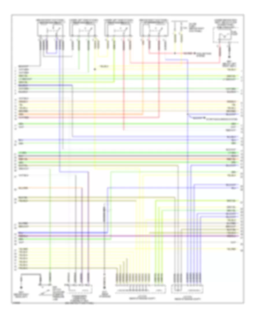
3.5L, Engine Performance Wiring Diagram, 4WD (6 of 6) for Honda Pilot LX 2006
List of elements for 3.5L, Engine Performance Wiring Diagram, 4WD (6 of 6) for Honda Pilot LX 2006:
- (middle of engine compartment)
- (on transmission housing) a/t clutch pressure control solenoid valve b
- (rear of engine compt) j/c c103
- (rear of engine) g101
- Afshtc b1
- Afshtc b2
- Altc
- Altf
- Altl
- Atf temperature sensor (on transaxle end cover)
- Atft
- Atp fwd
- Atp-1
- Atp-2
- Atp-d
- Atp-d3
- Atp-n
- Atp-r
- B20
- B21
- B22
- B23
- B24
- B25
- B26
- B27
- B28
- B29
- B30
- B31
- B32
- B33
- B34
- B35
- B36
- B37
- B38
- B39
- B40
- B41
- B42
- B43
- B44
- C10
- C11
- C12
- C13
- C14
- C15
- C16
- C17
- C18
- C19
- C20
- C21
- C22
- C23
- C24
- C25
- C26
- C27
- C28
- C29
- C30
- C31
- C32
- C33
- C34
- C35
- C36
- C37
- C38
- C39
- C40
- C41
- C42
- C43
- C44
- Ckpa
- Ckpb
- Cmp
- Ect sensor 1 (at rear of engine)
- Ect sensor 2 (at rear of engine)
- Ect1
- Ect2
- Egr
- Egrp
- Etcsm+
- Etcsm-
- G101 (rear of engine)
- G151
- Iat
- Iat sensor (on rear intake manifold chamber)
- Icm
- Ig1
- Ig1 etcs
- Ignition coil 1
- Ignition coil 2
- Ignition coil 3
- Ignition coil 4
- Ignition coil 5
- Ignition coil 6
- Igpls1
- Igpls2
- Igpls3
- Igpls4
- Ip b1
- Ip b2
- Knock sensor (left side of engine block)
- Lg1
- Lg2
- Lsa
- Lsb
- Lsc
- Map
- Nca
- Op3sw
- Op4sw
- Pcs
- Pg1
- Pgmetcs
- Pnk
- Powertrain control module (pcm) (right side of engine compt)
- Red
- Rocker arm oil control solenoid (vtec solenoid valve) (right side of engine compt)
- Sg1
- Sg2
- Sg5
- Sg6
- Sha
- Shb
- Shc
- So2shtc b1
- So2shtc b2
- Starting/ charging system
- Vcc2
- Vcent b1
- Vect b2
- Vlbl b1
- Vlbl b2
- Vtpsw
- Vts