ENGINE PERFORMANCE
3.7L VIN E
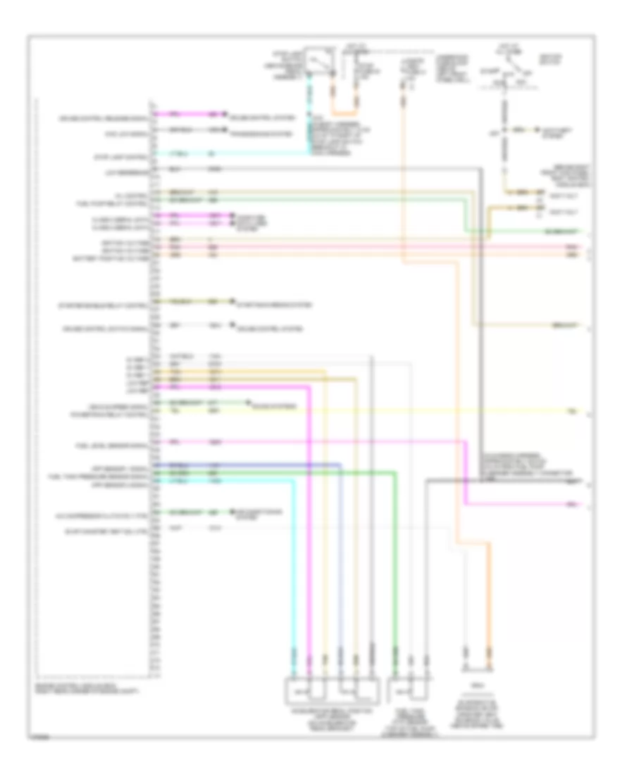
3.7L VIN E, Engine Performance Wiring Diagram (1 of 5) for Hummer H3 2008

List of elements for 3.7L VIN E, Engine Performance Wiring Diagram (1 of 5) for Hummer H3 2008:
- (behind right front kick panel) body control module (bcm)
- (in chassis harness, approximately 22.5 cm (8.9 in) from fuel pump & sender assembly connector) j359
- 4wd low signal
- 5v ref 1
- 5v ref 2
- A/c compressor clutch rly ctrl
- Acc
- Accelerator pedal position (app) sensor (on accelerator pedal bracket)
- Accy volt
- Air conditioning system
- Air solenoid relay control
- Anti-theft system
- App sensor 1 signal
- App sensor 2 signal
- Battery positive voltage
- Class 2 serial data
- Cnstr vent fuse 31 10a
- Computer data lines system
- Cruise control release signal
- Cruise control switch signal
- Cruise control system
- Engine control module (ecm) (right rear corner of engine compt)
- Evap canister vent sol ctrl
- Fuel level sensor signal
- Fuel pump relay control
- Fuel tank pressure (ftp) sensor (top of fuel pump & sender assembly)
- Fuel tank pressure sensor signal
- Hot at all times
- Ignition switch
- Ignition voltage
- J201
- Low ref
- Low reference
- Mil control
- Off
- Pnk
- Powertrain relay control
- Run
- Sound systems
- Start
- Starter enable relay control
- Starting/charging system
- Stop fuse 54 15a
- Stop lamp control
- Stop lamp switch (above brake pedal assembly)
- Tan
- Transmissions system
- Underhood fuse block (above left front wheelwell)
- Vehicle speed signal
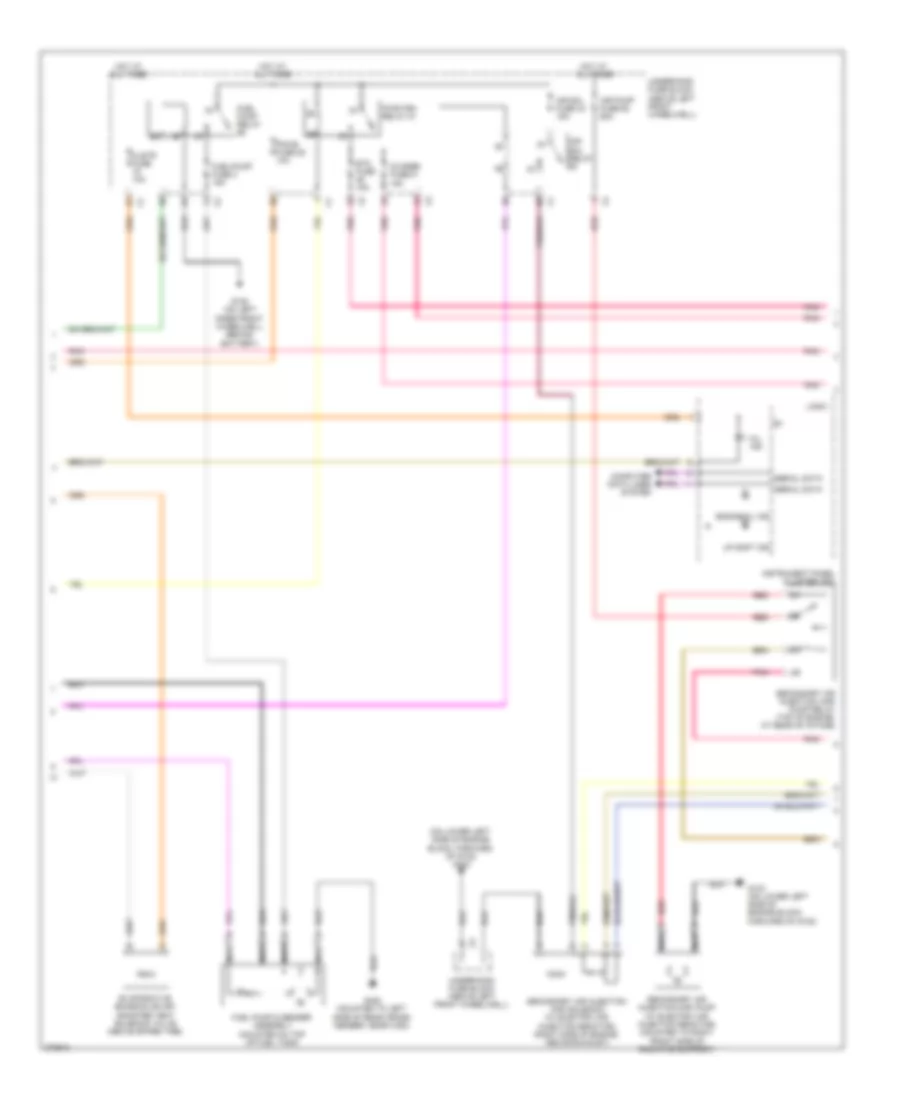
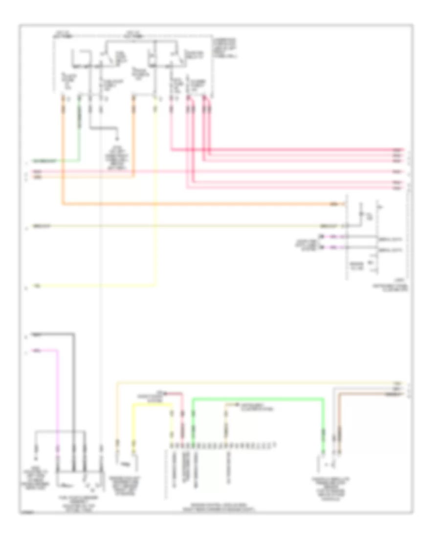
3.7L VIN E, Engine Performance Wiring Diagram (2 of 5) for Hummer H3 2008
List of elements for 3.7L VIN E, Engine Performance Wiring Diagram (2 of 5) for Hummer H3 2008:
- (on lower left side of engine block, forward of g102) g103
- Air pump fuse 62 60a
- Air sol fuse 44 15a
- Air sol relay
- Clstr fuse 10a
- Computer data lines system
- Engine oil ind
- Etc fuse 15a
- Evaporative emission (evap) canister vent solenoid valve (above spare tire)
- Fuel pump & sender assembly (mounted on top of fuel tank)
- Fuel pump relay
- Fuel/pump fuse 3 15a
- G103 (on lower left side of engine block, forward of g102)
- G105 (on left inner front wheelwell, behind battery)
- G420 (mounted to left side of rear cross member, near x420)
- Hot at all times
- Instrument panel cluster (ipc)
- Logic
- Mil ind
- Nca
- O2 snsr fuse 47 15a
- Pcm-b fuse 25 10a
- Pnk
- Pwr/trn relay 81
- Red
- Secondary air injection (air) pump (w/ electric air injection reactor) (mounted to right front side of radiator support)
- Secondary air injection (air) pump relay (top of engine, at rear of intake)
- Secondary air injection (air) solenoid (w/ electric air injection reactor) (right side of engine, above exhaust)
- Serial data
- Underhood fuse block (above left front wheelwell)
- Up shift ind
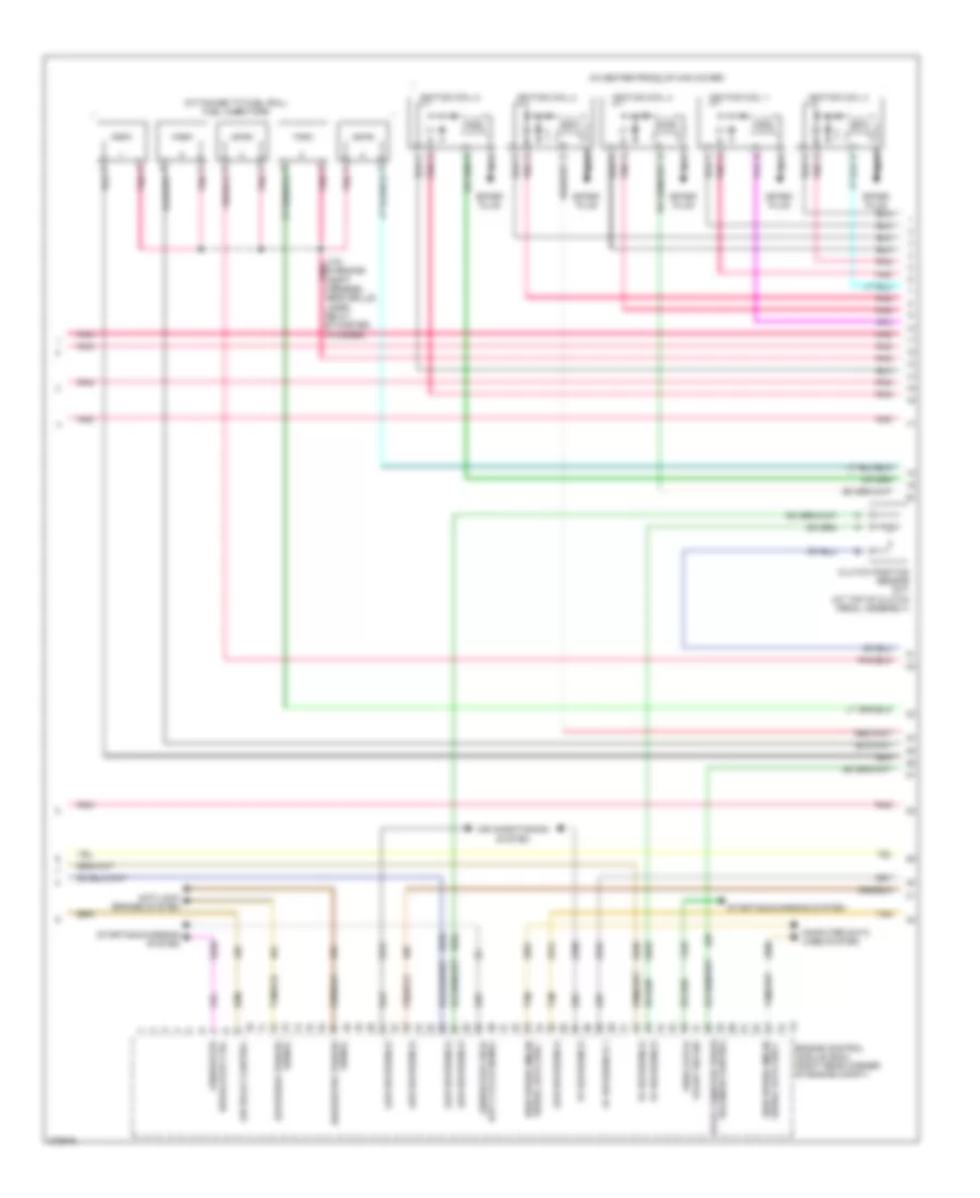
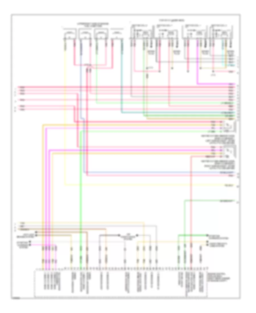
3.7L VIN E, Engine Performance Wiring Diagram (3 of 5) for Hummer H3 2008
List of elements for 3.7L VIN E, Engine Performance Wiring Diagram (3 of 5) for Hummer H3 2008:
- (attached to fuel rail) fuel injectors
- (in center front of cam cover)
- 5v reference
- 5v reference 1
- A pnk
- Air conditioning system
- Air relay control
- Anti-lock brakes system
- Clutch position sensor (m/t) (at top of clutch pedal assembly)
- Computer data lines system
- Delivered torque
- Duty cycle signal
- Engine control module (ecm) (right rear corner of engine compt)
- Evap canister purge
- Generator
- Generator field
- High speed gmlan
- Ignition coil 1
- Ignition coil 2
- Ignition coil 3
- Ignition coil 4
- Ignition coil 5
- J103 pnk (in engine compt harness, near grille lamps relay, by master cylinder)
- Low reference
- Nca
- Pnk
- Pnp/clutch
- Regulator ctrl
- Requested torque signal
- Serial data bus +
- Serial data bus -
- Signal
- Solenoid control
- Spark plug
- Start sw sig
- Starting/charging system
- Tan
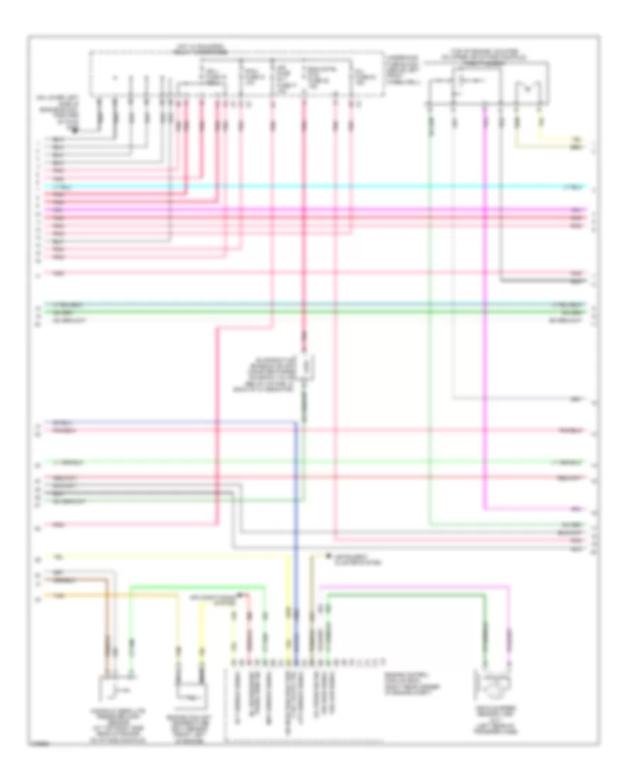
3.7L VIN E, Engine Performance Wiring Diagram (4 of 5) for Hummer H3 2008
List of elements for 3.7L VIN E, Engine Performance Wiring Diagram (4 of 5) for Hummer H3 2008:
- (on lower left side of engine block, forward of g102) g103
- (top of engine, mounted on upper air intake manifold) throttle body
- A/c refrigerant
- Air conditioning system
- Air injection reaction ctrl valve ctrl
- Air pump rly fuse 17 10a
- Cpp sensor signal
- Ect sensor signal
- Eng cntrl sys fuse 22 15a
- Engine control module (ecm) (right rear corner of engine compt)
- Engine coolant temperature (ect) sensor (front left of engine)
- Evaporative emission (evap) canister purge solenoid valve (below intake, in back of alternator)
- Hot w/ run/crnk relay 78 energized
- Ign 1 fuse 33 15a
- Inj fuse 23 15a
- Instrument cluster system
- Manifold absolute pressure (map) sensor (at top right side rear of engine, on intake manifold)
- Map sensor signal
- Nca
- Oil press sw sig
- Pcm-i fuse 21 10a
- Pnk
- Press sens sig
- Tan
- Underhood fuse block (above left front wheelwell)
- Vehicle speed sensor (vss) (m/t) (left rear of transfer case)
- Vss high signal
- Vss low signal
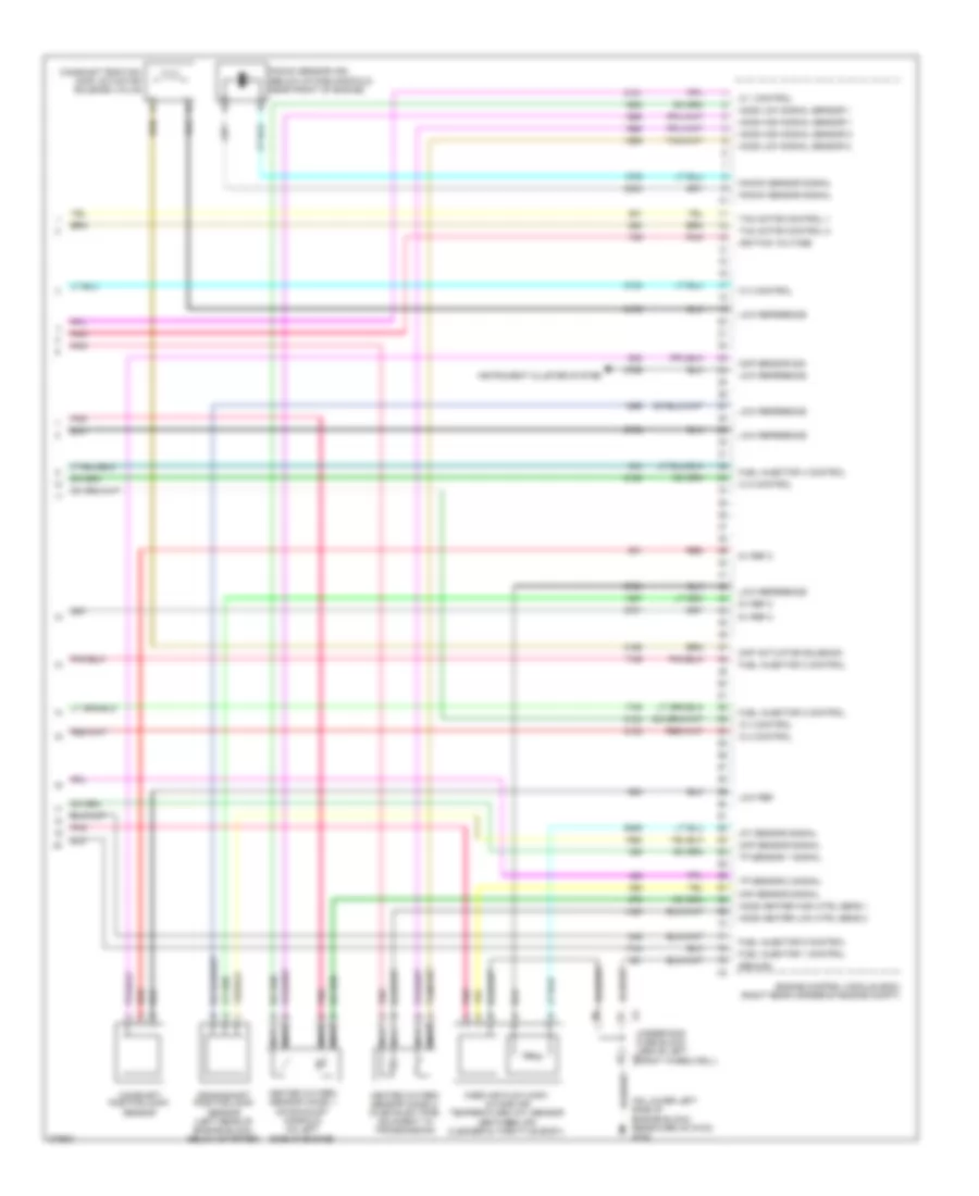
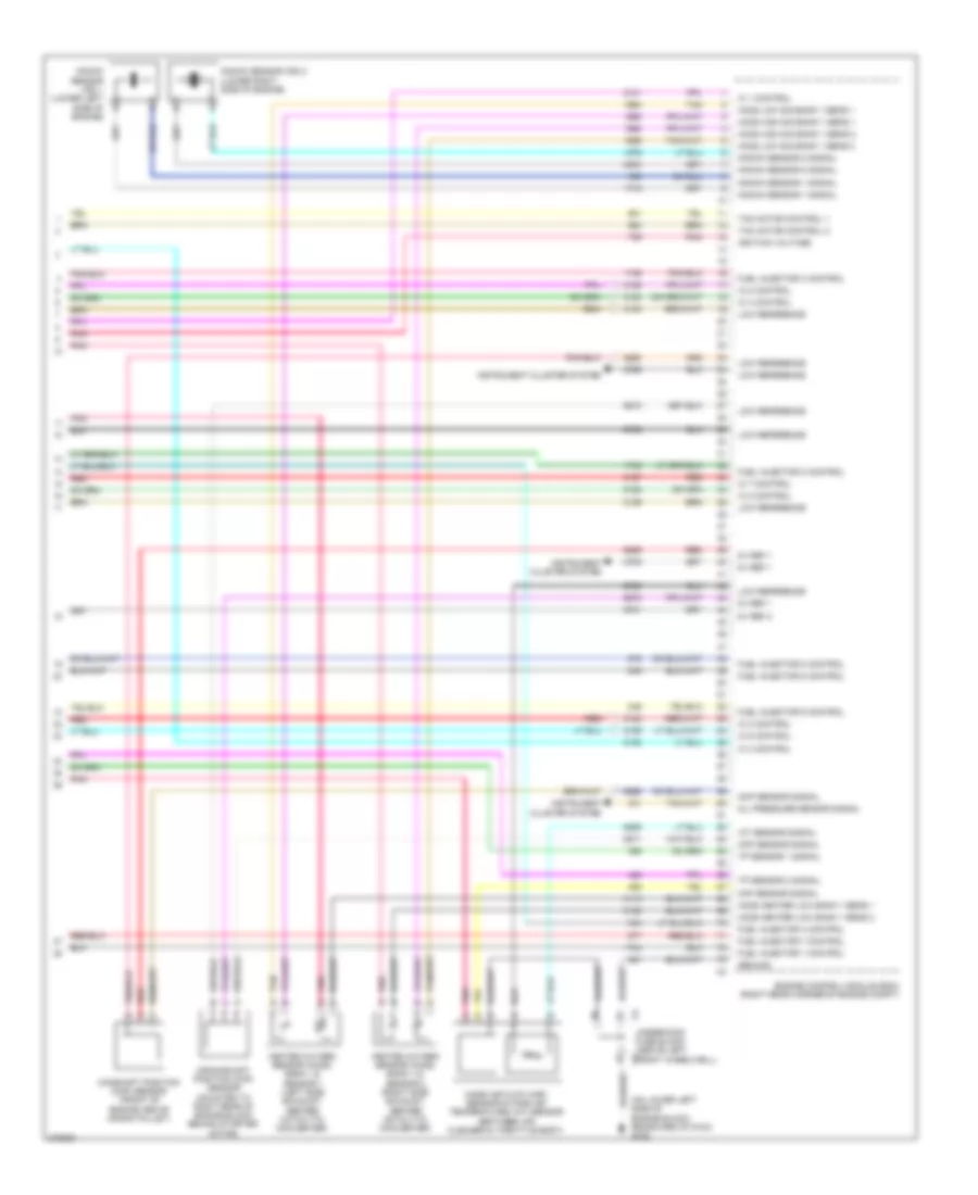
3.7L VIN E, Engine Performance Wiring Diagram (5 of 5) for Hummer H3 2008
List of elements for 3.7L VIN E, Engine Performance Wiring Diagram (5 of 5) for Hummer H3 2008:
- (on lower left side of engine block, rearward of g103) g102
- 5v ref 2
- Camshaft position (cmp) actuator solenoid valve
- Camshaft position (cmp) sensor
- Ckp sensor signal
- Cmp actuator solenoid
- Cmp sensor sig
- Crankshaft position (ckp) sensor (left rear of engine block, below starter)
- Engine control module (ecm) (right rear corner of engine compt)
- Fuel injector 1 control
- Fuel injector 2 control
- Fuel injector 3 control
- Fuel injector 4 control
- Fuel injector 5 control
- Ground
- Heated oxygen sensor (ho2s) 1 (on exhaust manifold on left side of engine)
- Heated oxygen sensor (ho2s) 2 (in exhaust pipe, adjacent to transmission)
- Ho2s heater high ctrl sens 1
- Ho2s heater low ctrl sens 2
- Ho2s high signal sensor 1
- Ho2s high signal sensor 2
- Ho2s low signal sensor 1
- Ho2s low signal sensor 2
- Iat sensor signal
- Ic 1 control
- Ic 2 control
- Ic 3 control
- Ic 4 control
- Ic 5 control
- Ignition voltage
- Instrument cluster system
- Knock sensor (ks) (below intake manifold, near front of engine)
- Knock sensor signal
- Low ref
- Low reference
- Maf sensor signal
- Mass air flow (maf)/ intake air temperature (iat) sensor (between air cleaner & throttle body)
- Nca
- Pnk
- Red
- Tac motor control 1
- Tac motor control 2
- Tp sensor 1 signal
- Tp sensor 2 signal
- X3 underhood fuse block (above left x3 front wheelwell)
5.3L VIN L
5.3L VIN L, Engine Performance Wiring Diagram (1 of 5) for Hummer H3 2008
List of elements for 5.3L VIN L, Engine Performance Wiring Diagram (1 of 5) for Hummer H3 2008:
- (behind right front kick panel) body control module (bcm)
- (in chassis harness, approximately 22.5 cm (8.9 in) from fuel pump & sender assembly connector) j359
- 4wd low signal
- 5v ref 1
- 5v ref 2
- A/c compressor clutch rly ctrl
- Acc
- Accelerator pedal position (app) sensor (on accelerator pedal bracket)
- Accy volt
- Air conditioning system
- Anti-theft system
- App sensor 1 signal
- App sensor 2 signal
- Battery positive voltage
- Class 2 serial data
- Cnstr vent fuse 31 10a
- Computer data lines system
- Cruise control release signal
- Cruise control switch signal
- Cruise control system
- Engine control module (ecm) (right rear corner of engine compt)
- Evap canister vent sol ctrl
- Evaporative emission (evap) canister vent solenoid valve (above spare tire)
- Fuel level sensor signal
- Fuel pump relay control
- Fuel tank pressure (ftp) sensor (top of fuel pump & sender assembly)
- Fuel tank pressure sensor signal
- Hot at all times
- Ignition switch
- Ignition voltage
- J201
- Low ref
- Low reference
- Mil control
- Off
- Pnk
- Powertrain relay control
- Run
- Sound systems
- Start
- Starter enable relay control
- Starting/charging system
- Stop fuse 54 15a
- Stop lamp control
- Stop lamp switch (above brake pedal assembly)
- Tan
- Transmissions system
- Underhood fuse block (above left front wheelwell)
- Vehicle speed signal
5.3L VIN L, Engine Performance Wiring Diagram (2 of 5) for Hummer H3 2008
List of elements for 5.3L VIN L, Engine Performance Wiring Diagram (2 of 5) for Hummer H3 2008:
- A/c refrigerant
- Air conditioning system
- Clstr fuse 10a
- Computer data lines system
- Ect sensor signal
- Engine control module (ecm) (right rear corner of engine compt)
- Engine coolant temperature (ect) sensor (front left of engine)
- Engine oil ind
- Etc fuse 15a
- Fuel pump & sender assembly (mounted on top of fuel tank)
- Fuel pump relay
- Fuel/pump fuse 3 15a
- G105 (on left inner front wheelwell, behind battery)
- G420 (mounted to left side of rear cross member, near x420)
- Hot at all times
- Instrument cluster system
- Instrument panel cluster (ipc)
- Logic
- Manifold absolute pressure (map) sensor (top of engine, above intake manifold)
- Map sensor signal
- Mil ind
- Nca
- O2 snsr fuse 47 15a
- Oil press sw sig
- Pcm-b fuse 25 10a
- Pnk
- Press sens sig
- Pwr/trn relay 81
- Serial data
- Tan
- Underhood fuse block (above left front wheelwell)
5.3L VIN L, Engine Performance Wiring Diagram (3 of 5) for Hummer H3 2008
List of elements for 5.3L VIN L, Engine Performance Wiring Diagram (3 of 5) for Hummer H3 2008:
- (top of cylinder head)
- (upper right side of engine) fuel injectors
- 5v reference
- 5v reference 1
- A pnk
- Air conditioning system
- Anti-lock brakes system
- Bank 2 & sens 1
- Bank 2 & sens 2
- C red
- Computer data lines system
- D pnk
- Delivered torque
- Duty cycle signal
- Engine control module (ecm) (right rear corner of engine compt)
- Evap canister purge
- Generator field
- Heated oxygen sensor (ho2s) bank 2 & sensor 1 (left side exhaust, after catalytic converter)
- Heated oxygen sensor (ho2s) bank 2 & sensor 2 (right side exhaust, after catalytic converter)
- High speed gmlan
- Ho2s heater low
- Ignition coil 1
- Ignition coil 3
- Ignition coil 5
- Ignition coil 7
- J113
- J114
- J118
- Low reference
- Nca
- Pnk
- Pnp/clutch
- Red
- Regulator ctrl generator
- Requested torque signal
- Serial data bus +
- Serial data bus -
- Signal
- Solenoid control
- Spark plug
- Start sw sig
- Starting/ charging system
- Tan
5.3L VIN L, Engine Performance Wiring Diagram (4 of 5) for Hummer H3 2008
List of elements for 5.3L VIN L, Engine Performance Wiring Diagram (4 of 5) for Hummer H3 2008:
- (on lower left side of engine block, forward of g102) g103
- (top of cylinder head)
- (top of engine, mounted on upper air intake manifold) throttle body
- Eng cntrl sys fuse 22 15a
- Evaporative emission (evap) canister purge solenoid valve (top of intake manifold near rear of throttle body)
- Fuel injectors (upper left side of engine)
- G103 (on lower left side of engine block, forward of g102)
- Hot w/ run/crnk relay 78 energized
- Ign 1 fuse 33 15a
- Ignition coil 2
- Ignition coil 4
- Ignition coil 6
- Ignition coil 8
- Inj fuse 23 15a
- J111
- J116
- J117
- Nca
- Pcm-i fuse 21 10a
- Pnk
- Pnk a
- Pnk d
- Red
- Red c
- Spark plug
- Underhood fuse block (above left front wheelwell)
5.3L VIN L, Engine Performance Wiring Diagram (5 of 5) for Hummer H3 2008
List of elements for 5.3L VIN L, Engine Performance Wiring Diagram (5 of 5) for Hummer H3 2008:
- (on lower left side of engine block, rearward of g103) g102
- 5v ref 1
- 5v ref 2
- Camshaft position (cmp) sensor (front of engine above crank pulley)
- Ckp sensor signal
- Cmp sensor signal
- Crankshaft position (ckp) sensor (mounted to right rear of engine block behind starter motor)
- Engine control module (ecm) (right rear corner of engine compt)
- Engine)
- Fuel injector 1 control
- Fuel injector 2 control
- Fuel injector 3 control
- Fuel injector 4 control
- Fuel injector 5 control
- Fuel injector 6 control
- Fuel injector 7 control
- Fuel injector 8 control
- Ground
- Heated oxygen sensor (ho2s) bank 1 & sensor 1 (left side exhaust, before catalytic converter)
- Heated oxygen sensor (ho2s) bank 1 & sensor 2 (right side exhaust, before catalytic converter)
- Ho2s heater low bank 1 sens 1
- Ho2s heater low bank 1 sens 2
- Ho2s high sig bank 1 sens 1
- Ho2s high sig bank 1 sens 2
- Ho2s low sig bank 1 sens 1
- Ho2s low sig bank 1 sens 2
- Iat sensor signal
- Ic 1 control
- Ic 2 control
- Ic 3 control
- Ic 4 control
- Ic 5 control
- Ic 6 control
- Ic 7 control
- Ic 8 control
- Ignition voltage
- Instrument cluster system
- Knock sensor (ks) 1 (lower left side of b
- Knock sensor (ks) 2 (lower right side of engine)
- Knock sensor 1 signal
- Knock sensor 2 signal
- Low reference
- Maf sensor signal
- Mass air flow (maf) sensor/intake air temperature (iat) sensor (between air cleaner & throttle body)
- Oil pressure sensor signal
- Pnk
- Red
- Tac motor control 1
- Tac motor control 2
- Tan
- Tp sensor 1 signal
- Tp sensor 2 signal
- X3 underhood fuse block (above left x3 front wheelwell)