ENGINE PERFORMANCE
3.3L
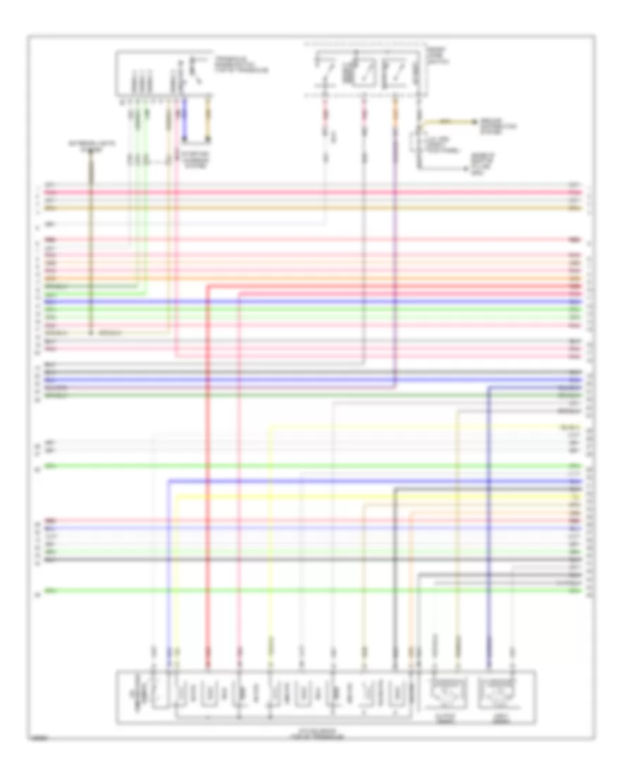
3.3L, Engine Performance Wiring Diagram (1 of 7) for Hyundai Azera 2013

List of elements for 3.3L, Engine Performance Wiring Diagram (1 of 7) for Hyundai Azera 2013:
- (left rear of
- Alternator com
- Ams fuse 10a
- Aps 1 ground
- Aps 1 signal
- Aps 2 ground
- Aps 2 signal
- Apt ground
- Apt signal
- Brake lamp switch
- C-can low
- C/fan relay high
- Canister close valve (on fuel filler neck)
- Ccp-can low
- Computer data lines system
- Cooling fans system
- Down shift
- E/r fuse & relay box
- E/r-a
- E/r-b
- Ec21
- Ecu 1 fuse 30a
- Ecu 2 fuse 10a
- Ecu 3 fuse 15a
- Ecu/ sensor 1 fuse 15a
- Ecu/ sensor 2 fuse 10a
- Ef11
- Ef21
- Elg-a
- Em31
- Ems box
- Eng ctrl rly on input
- Engine compt) ge05
- Engine control relay
- F/pump fuse 20a
- F/pump relay
- Ftps ground
- Ftps power
- Fuel level sens 2
- Fuel pump motor
- Fuel sender
- Fuel sender & fuel pump motor (top of fuel tank)
- Fuel tank pressure sensor (top of fuel tank)
- Gf02 (base of left "b" pillar)
- Ground
- Hot at all times
- Ign coil fuse 20a
- Immo data line
- Immobilizer module (top left side of dash)
- Injector fuse 10a
- Instrument cluster system
- Lin line
- M13-a
- Memory power
- On/start input
- Pcm (left rear of engine compt)
- Pnk
- Pos sw code s1
- Pos sw code s2
- Pos sw code s3
- Pos sw code s4
- Rail pressure snsr sig
- Red
- Rpm signal
- Select sw
- Sensor ground
- Smart key control module (w/ smart key) (center of dash)
- Snsr +
- Up shift
- W/ smart key
- W/o smart key
3.3L, Engine Performance Wiring Diagram (2 of 7) for Hyundai Azera 2013
List of elements for 3.3L, Engine Performance Wiring Diagram (2 of 7) for Hyundai Azera 2013:
- (base of right"b" pillar) gf03
- 26-vfs
- 35r-vfs
- Atm solenoid (top of transaxle)
- Down shift
- Ec21
- Ef21
- Exterior lights
- Ground distribution system
- Input speed
- J/c jf05 (right kick panel)
- Line-vfs
- Od-vfs
- On/start in
- Output speed
- P/n sw
- Pnk
- Red
- Select switch
- Sensor
- Signal 1
- Signal 2
- Signal 3
- Signal 4
- Sport mode switch
- Ss-a
- Ss-b
- Starting/ charging system
- System
- T/con-vfs
- Temperature oil
- Transaxle range switch (top of transaxle)
- Ud-vfs
- Up shift
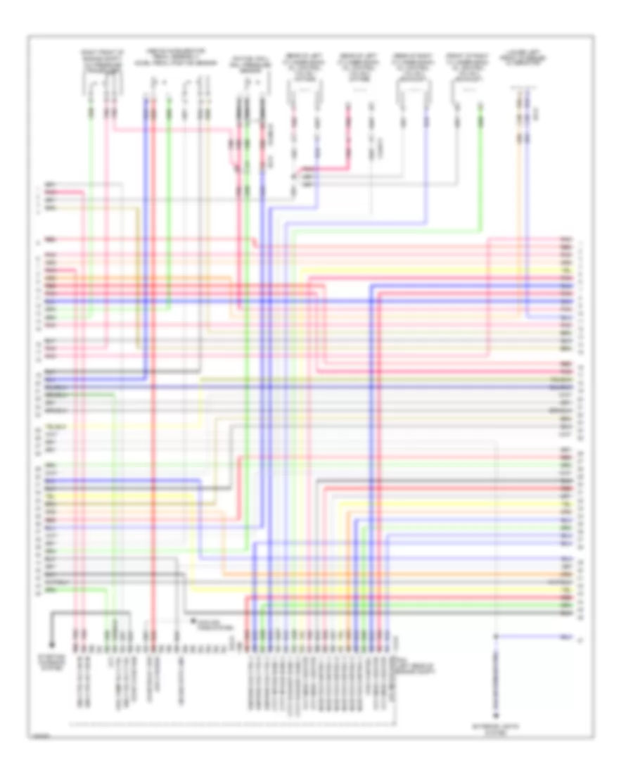
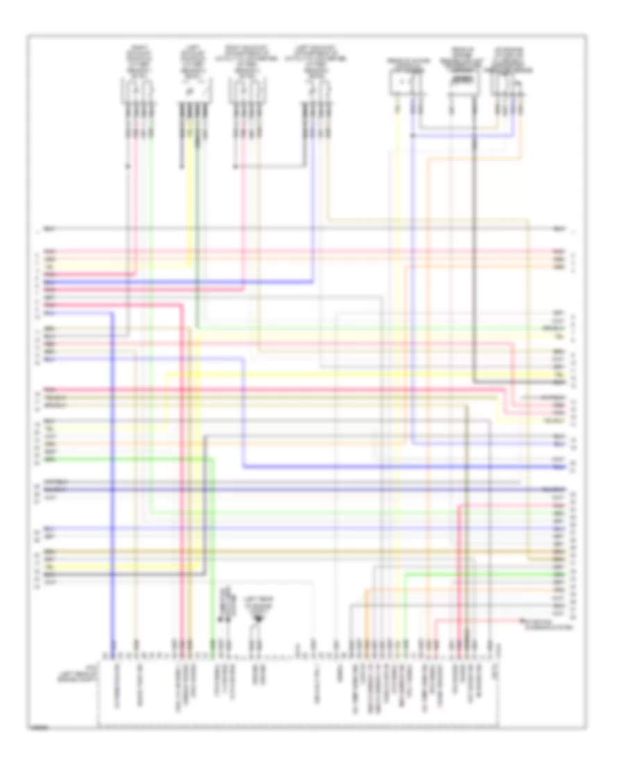
3.3L, Engine Performance Wiring Diagram (3 of 7) for Hyundai Azera 2013
List of elements for 3.3L, Engine Performance Wiring Diagram (3 of 7) for Hyundai Azera 2013:
- (above accelerator pedal assembly) accel pedal position sensor
- (front of right cylinder head) oil control valve 4 (exhaust)
- (lower left front of engine) alternator
- (on fuel rail)
- (rear of left cylinder bank) oil control valve 1 (intake)
- (rear of left cylinder bank) oil control valve 2 (intake)
- (rear of right cylinder bank) oil control valve 3 (exhaust)
- (right front of engine compt)
- A/c pressure transducer
- Aps 2 power
- C/fan relay low
- Ccv
- Clg-b
- Clginj-b
- Clgocv
- Cooling fans system
- Cvvt exhaust bank 1
- Cvvt exhaust bank 2
- Cvvt intake bank 1
- Cvvt intake bank 2
- Ec21
- Elg-a
- Eng ctrl rly ctrl
- Eng ctrl rly on in
- Etc motor (low)
- Exterior lights system
- Fprv control
- Fuel pump rly ctrl
- Ignition coil ctrl 2
- Ignition coil ctrl 4
- Ignition coil ctrl 6
- Injector control 1
- Injector control 2
- Injector control 3
- Injector control 4
- Injector control 5
- Injector control 6
- Lin diag data line
- Nca
- Oxy snsr 1 heater
- Oxy snsr 2 heater
- Oxy snsr 3 heater
- Oxy snsr 4 heater
- Pcm (left rear of engine compt)
- Pnk
- Rail pressure sensor
- Red
- Start over run
- Starting/ charging system
3.3L, Engine Performance Wiring Diagram (4 of 7) for Hyundai Azera 2013
List of elements for 3.3L, Engine Performance Wiring Diagram (4 of 7) for Hyundai Azera 2013:
- Anti- theft system
- C-can transceiver
- Circuit
- Clgign
- Close w/ brake
- Computer data lines system
- Conden- ser 1 (front of
- Condenser 2 (front of left cylinder bank)
- Cruise ind
- Der bank)
- Ec21
- Em31
- Engine check ind
- Exterior lights system
- Fuel input
- Ge05 (left rear of engine compt)
- Ge07 (right end of dash)
- Glg01 (left front of engine)
- High
- Hot at all times
- Hot in on or start
- I/p-c
- I/p-d
- Ignition coils 1, 3 & 5 (top of right cylinder bank)
- Ignition coils 2, 4 & 6 (top of left cylinder bank)
- Immo ind
- Instrument cluster
- Instrument cluster system
- J/c je03 (left side of dash)
- Joint block jm01 (center of dash)
- Leak current autocut device
- Left cylin-
- Low
- Mcu
- Memory 1 fuse 10a
- Module 1 fuse 10a
- Nca
- Open w/ brake
- Pedal depressed
- Pnk
- Power distribution system
- Red
- Set ind
- Smart junction box
- Stop lamp fuse 10a
- Stop lamp switch (above brake pedal, on bracket)
- Stop signal relay (left end of dash)
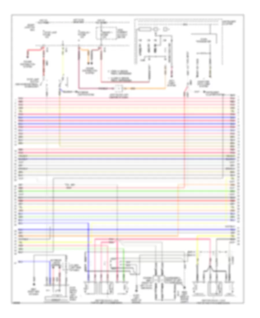
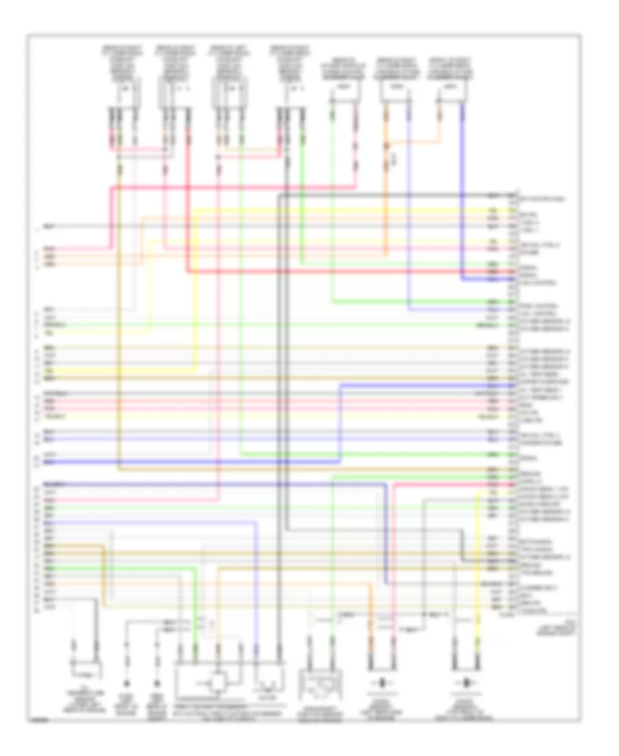
3.3L, Engine Performance Wiring Diagram (5 of 7) for Hyundai Azera 2013
List of elements for 3.3L, Engine Performance Wiring Diagram (5 of 7) for Hyundai Azera 2013:
- (center of dash) smart key control module
- (left rear of engine compt)
- (left rear of engine compt) abs control module
- (left rear of engine compt) esc module
- (top left side of engine) fuel pressure regulator valve
- (top of left cylinder bank) injectors
- (top of right cylinder bank) injectors
- Ccp can high
- Ccp can low
- Clginj-a
- Clginj-b
- E/r fuse & relay box
- Ec21
- Ecu 4 fuse 10a
- Em31
- Engine ctrl rly on in
- Fu pr reg val hi
- Fu pr reg val lo
- Fuel pr reg val sig
- Ge05
- Ground
- Idb (injector driver box) (left rear of engine compt)
- Ign 1 fuse 15a
- Injector 1 signal
- Injector 2 signal
- Injector 3 signal
- Injector 4 signal
- Injector 5 signal
- Injector 6 signal
- Injector ctrl 1 hi
- Injector ctrl 1 lo
- Injector ctrl 2 hi
- Injector ctrl 2 lo
- Injector ctrl 3 hi
- Injector ctrl 3 lo
- Injector ctrl 4 hi
- Injector ctrl 4 lo
- Injector ctrl 5 hi
- Injector ctrl 5 lo
- Injector ctrl 6 hi
- Injector ctrl 6 lo
- M13-b
- Memory power
- Nca
- On/start input
- Pnk
- Power ground
- Red
- System data lines computer
- W/ abs
- W/ esc
3.3L, Engine Performance Wiring Diagram (6 of 7) for Hyundai Azera 2013
List of elements for 3.3L, Engine Performance Wiring Diagram (6 of 7) for Hyundai Azera 2013:
- (left exhaust manifold) oxygen sensor 2 (b2/s1)
- (left exhaust, downstream of catalytic converter) oxygen sensor 4 (b2/s2)
- (left rear
- (on engine intake air filter box) barometric pressure sensor
- (rear of engine) engine coolant temperature sensor
- (rear of intake manifold) map sensor
- (right exhaust manifold) oxygen sensor 1 (b1/s1)
- (right exhaust, downstream of catalytic converter) oxygen sensor 3 (b1/s2)
- Alternator (fr)
- Aps1 power
- Ats signal
- Bps signal
- Brake test sw
- C-can high
- Ccp-can high
- Ckps hi
- Clg-b
- Crank request
- Elg-a
- Ftps signal
- Fuel lvl in sens 1
- Ground
- Ign coil ctrl 1
- In speed sig
- Knock sensor 1 hi
- Knock sensor 2 hi
- Map sensor sig
- Nca
- Od vf
- Of engine compt) ge05
- Oil temp sens gnd
- Oil temp sens sig
- Out speed sig
- Pcm (left rear of engine compt)
- Pnk
- Power
- Red
- Sensor
- Sensor power
- Signal
- Starting/ charging system
- System data lines computer
- Tps 1 signal
- Tps power
- Vehicle spd in
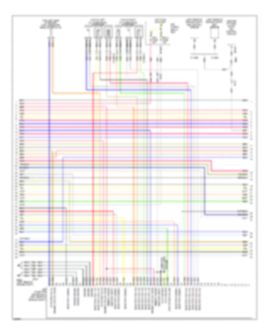
3.3L, Engine Performance Wiring Diagram (7 of 7) for Hyundai Azera 2013
List of elements for 3.3L, Engine Performance Wiring Diagram (7 of 7) for Hyundai Azera 2013:
- (front of right cylinder bank)
- (rear of intake manifold)
- (rear of left cylinder bank) camshaft position sensor 4 (exhaust)
- (rear of right cylinder bank)
- (rear of right cylinder bank) camshaft position sensor 1 (intake)
- (rear of right cylinder bank) camshaft position sensor 2 (exhaust)
- (rear of right cylinder bank) camshaft position sensor 3 (intake)
- 26-vfs
- 35r-vfs
- Ckps lo
- Clg-b
- Crankshaft position sensor (rear of engine)
- Ec21
- Ects signal
- Etc motor & throttle position sensor (on throttle body)
- Etc motor (high)
- Ge05 (left rear of engine compt)
- Glg01 (left front of engine)
- Ground
- Ign coil ctrl 3
- Ign coil ctrl 5
- In speed sply
- Knock sens 1 low
- Knock sens 2 low
- Knock sensor 1 (left rear side of engine)
- Knock sensor 2 (top front of right cylinder bank)
- Line-vfs
- Map/bps power
- Map/ects bps gnd
- Motor
- Nca
- Oil temp sens +
- Oil temp sens -
- Oil temperature sensor (lower left rear of engine)
- Out speed sply
- Oxygen sensor hi
- Oxygen sensor lo
- Pcm (left rear of engine compt)
- Pcsv control
- Pnk
- Power
- Purge control solenoid valve
- Red
- Shield ground
- Signal
- Ss-a
- Ss-b
- T/con-vfs
- Throttle position sensor
- Tps 2 signal
- Tps ground
- Ud-vfs
- V-sol 1
- V-sol 2
- Variable intake solenoid valve 1
- Variable intake solenoid valve 2
- Vis 1 control
- Vis 2 control