ENGINE PERFORMANCE
2.0L
2.0L, Engine Performance Wiring Diagram (1 of 3) for Hyundai Elantra GLS 2003

List of elements for 2.0L, Engine Performance Wiring Diagram (1 of 3) for Hyundai Elantra GLS 2003:
- (on firewall, above brake pedal) g22
- (on rear of engine, near coolant outlet) engine coolant temperature (ect) sensor & sender
- 5v sensor pwr
- Abs control module (in right front corner of engine compt)
- Batt
- Canister purge valve (on left rear of engine compt)
- Comm area network hi
- Comm area network lo
- Cpv ctrl
- Crankshaft position (ckp) sensor (on left rear of engine)
- Cruise control system
- Data link connector (below left side of dash)
- E37
- Ec03
- Ec04
- Ecm (behind left side of dash, above kick panel)
- Ect in
- Emo2
- Engine compartment relay & fuse box (in left front corner of engine compt, behind battery)
- Engine control relay
- Fuel pump motor
- Fuel pump relay
- Fuel sender & fuel pump motor (below center of rear seat)
- Fusible link (ecu) 20a
- G04 (at middle front of of rear seat, under carpet)
- Gnd
- Heated oxygen sensor (down) (below exhaust manifold)
- Heated oxygen sensor (up) (on front exhaust pipe, between catalytic converters)
- Hot at all times
- Ign coil 1 (cyl 1,4)
- Ign coil 2 (cyl 2,3)
- Inj 1 ctrl
- Inj 4 ctrl
- Inj fuse (diagram 2 of 3)
- Instrument cluster system
- Joint con- nector c91 (left side of dash)
- Joint con- nector m33 (left side of dash)
- Joint connector e57
- Joint connector e58
- Nca
- O2s heating
- O2s sig
- On/start in
- Pnk
- Red
- Right front wheel sensor (w/o abs) (on right front hub assembly)
- Sensor gnd
- Sensor pwr
- Sensor sig
- Vehicle speed in
- W/ abs only
- W/o abs only
- Wheel speed sens in
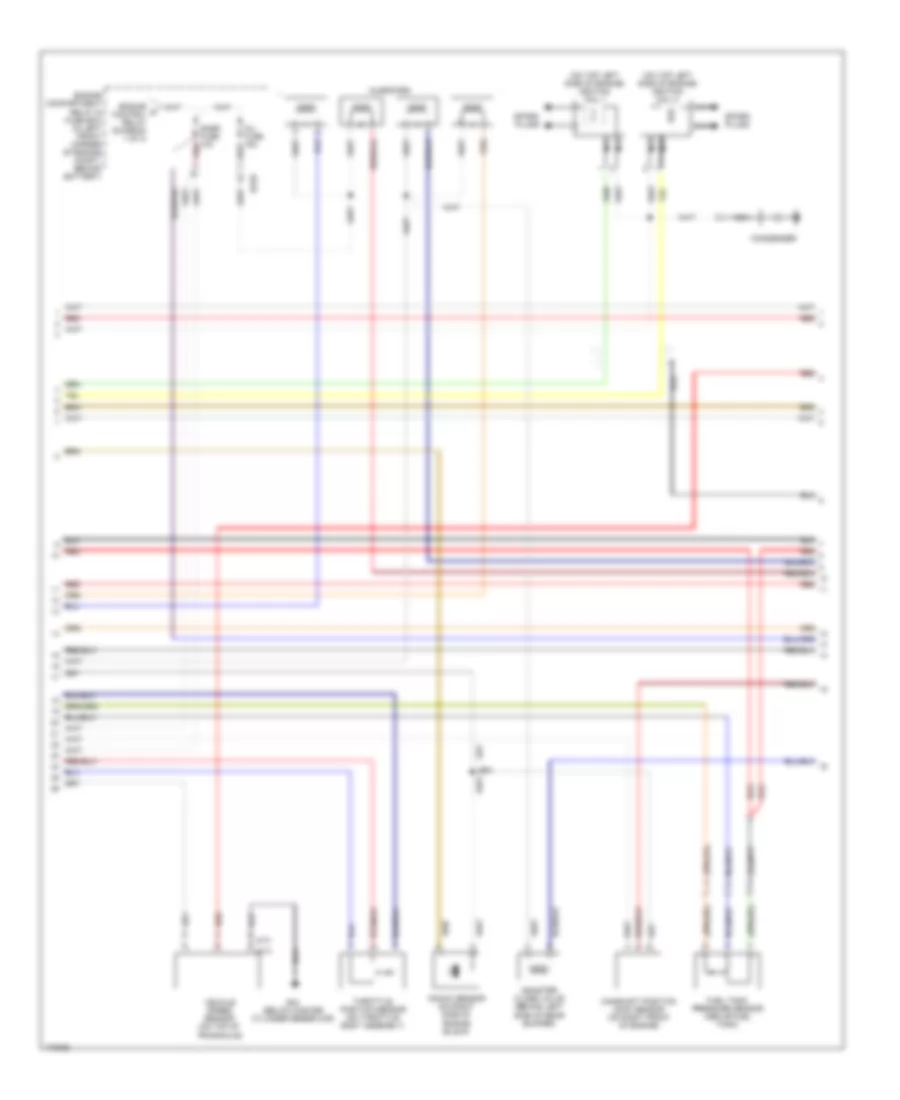
2.0L, Engine Performance Wiring Diagram (2 of 3) for Hyundai Elantra GLS 2003
List of elements for 2.0L, Engine Performance Wiring Diagram (2 of 3) for Hyundai Elantra GLS 2003:
- (a/t)
- (m/t)
- (on top left side of engine) ignition coil 1
- (on top left side of engine) ignition coil 2
- Camshaft position (cmp) sensor (on right front of engine)
- Canister close valve (behind left side of rear bumper)
- Condenser
- Ec03
- Engine a control relay (diagram 1 of 3)
- Engine compartment relay & fuse box (in left front corner of engine compt, behind battery)
- Fuel tank pressure sensor (above fuel tank)
- G23 (below master cylinder reservoir)
- Inj fuse 15a
- Injectors
- Knock sensor (on right side of engine block)
- Nca
- Pnk
- Red
- Snsr fuse 10a
- Spark plugs
- Throttle position sensor (on throttle body assembly)
- Vehicle speed sensor (on top of transaxle)
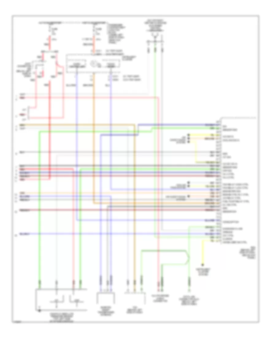
2.0L, Engine Performance Wiring Diagram (3 of 3) for Hyundai Elantra GLS 2003
List of elements for 2.0L, Engine Performance Wiring Diagram (3 of 3) for Hyundai Elantra GLS 2003:
- (on top right center of engine) idle speed control actuator
- (w/ trip comp)
- (w/o trip comp)
- 11 (or 12)
- A/c relay ctrl
- A/c sig in
- A/c sw on in
- A/t
- Air conditioning system
- Ccv ctrl
- Closing
- Consumption
- Cooling fans system
- Cooling sig in
- Data link connector (dlc) (below left side of dash)
- Diagnosis k-line
- Ecm (behind left side of dash, above kick panel)
- Engine ctrl rly ctrl
- Engine rpm sig
- Fan relay (high) ctrl
- Fan relay (low) ctrl
- Fuel pump relay ctrl
- Fuse 10a
- Gnd
- Hot in on or start
- I/p-h
- Iat
- Iat sig
- Immobilizer ind ctrl
- Inj 2 ctrl
- Inj 3 ctrl
- Instrument cluster
- Instrument cluster system
- Joint connector c92 (below left side of dash)
- M/t
- M09-1
- M09-2
- M10-1
- Manifold absolute pressure sensor (top left side of intake manifold)
- Map
- Map sig
- Micro- controller
- Mil ind
- Mil ind ctrl
- Multipurpose check connector
- Opening
- Passenger compartment junction block (under left side of dash, near kick panel)
- Red
- Sensor gnd
- Sensor sig
- Sig
- Smartra (smart transponder antenna)
- Tacho- meter
- Tcm (behind left side of dash)