ENGINE PERFORMANCE
2.0L
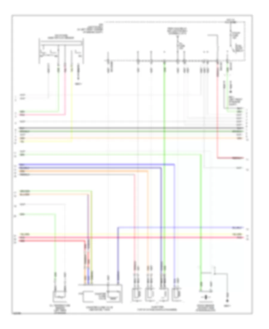
2.0L, Engine Performance Wiring Diagram (1 of 3) for Hyundai Elantra GLS 2010

List of elements for 2.0L, Engine Performance Wiring Diagram (1 of 3) for Hyundai Elantra GLS 2010:
- (left rear of engine)
- A/c pressure transducer (right side of engine compt)
- Anti-theft system
- Apt 5v
- Apt gnd
- Apt sig
- Batt pwr
- Box (in left front of engine compt)
- Cruise control system
- E/r junction
- E/r-cbg
- Ect sens gnd
- Ect sens sig
- Ecu 2 fuse 10a
- Ecu fusible link 30a
- Engine control module (left rear of engine compt)
- Gbg11
- Gnd
- Hot at all times
- Hot in on or start
- Htr
- Ign coil ctrl cyl 1, 4
- Ign coil ctrl cyl 2, 3
- Ignition coil
- Ignition coil 1
- Ignition coil 2
- Inj ctrl 1
- Inj ctrl 2
- Inj ctrl 3
- Inj ctrl 4
- Knock sens gnd
- Knock sens sig
- Linear lambda vg
- Linear lambda vip
- Linear lambda vn
- Linear lambda vrc
- Maf/map/tia sens gnd
- Main relay
- Main rly on in
- Map/ mass signal
- Nca
- Nca vg
- Nca vip
- Nca vn
- Nca vrc
- On/start in
- Ots gnd
- Ots sig
- Oxygen sensor (down) (rear of engine compt, in exhaust)
- Oxygen sensor (up)
- Pnk
- Red
- Right front wheel sensor (w/o abs/esc) (right front wheel hub assembly)
- Sens gnd
- Sens pwr
- Sens sig
- Shld gnd
- Sig
- Snr
- Snsr 1 fuse 10a
- Throttle position sensor (on throttle body assembly)
- Tia sens in
- To inj fuse e/r junction box (diagram 2 of 3)
- To spark plugs
- Tps 5v
- Tps gnd
- Tps sig
- Veh spd
- Whl spd in (+)
- Whl spd in (-)
2.0L, Engine Performance Wiring Diagram (2 of 3) for Hyundai Elantra GLS 2010
List of elements for 2.0L, Engine Performance Wiring Diagram (2 of 3) for Hyundai Elantra GLS 2010:
- (on intake) mass air flow sensor
- Canister close valve
- Canister close valve (above fuel tank)
- E/r junction box (in left front corner of engine compt)
- E/r-cbg
- E/r-erom
- E/r-frt
- F/pump fuse 15a
- From main relay e/r junction box (diagram 1 of 3)
- Ftp
- Fuel pump relay
- Gbg11
- Ge11 (left front of engine compt)
- Hot at all times
- Inj fuse 15a
- Injectors (top of intake manifold runners)
- Knock sensor (on right side of engine block)
- Nca
- Oil temperature sensor (left rear of engine)
- Pnk
- Red
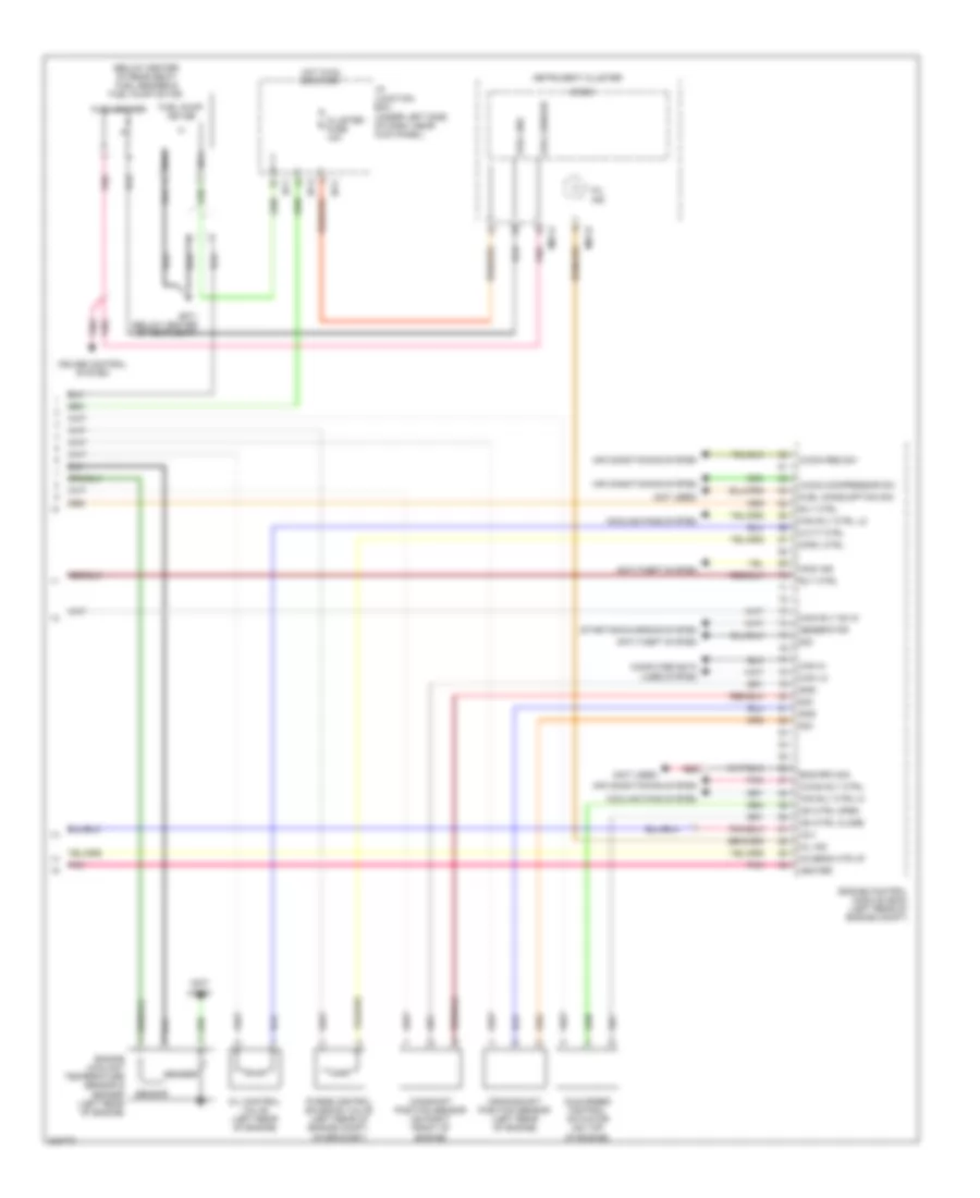
2.0L, Engine Performance Wiring Diagram (3 of 3) for Hyundai Elantra GLS 2010
List of elements for 2.0L, Engine Performance Wiring Diagram (3 of 3) for Hyundai Elantra GLS 2010:
- (below center of rear seat) fuel sender & fuel pump motor
- (not used)
- A/con compressor sw
- A/con req sw
- A/con rly ctrl
- Air conditioning system
- Anti-theft system
- Camshaft position sensor (on right front of engine)
- Can hi
- Can lo
- Ccv
- Cluster fuse 10a
- Computer data lines system
- Cooling fans system
- Cpsv ctrl
- Crankshaft position sensor (left rear of engine)
- Cruise control system
- Cvvt ctrl
- Eng rpm sig
- Engine control module (ecm) (left rear of engine compt)
- Engine coolant temperature sensor & sender (left rear of engine)
- Fan rly ctrl hi
- Fan rly ctrl lo
- Fuel consumption sig
- Fuel gnd
- Fuel pump motor
- Fuel sender
- Generator
- Gf71 (below center of rear seat)
- Gnd
- Heater
- Hot in on or start
- I/p junction box (under left side of dash, near kick panel)
- I/p-c
- I/p-f
- I/p-g
- Idle speed control actuator (on top of engine)
- Immo ind
- Instrument cluster
- Isa ctrl close
- Isa ctrl open
- M01-a
- M01-b
- Main rly on in
- Micom
- Mil ind
- Nca
- O2 sens htr up
- Oil control valve (left rear of engine)
- Pnk
- Purge control solenoid valve (left rear of engine compt, on bracket)
- Red
- Rly ctrl
- Sender
- Sensor
- Sig
- Starting/charging system