ENGINE PERFORMANCE
2.0L
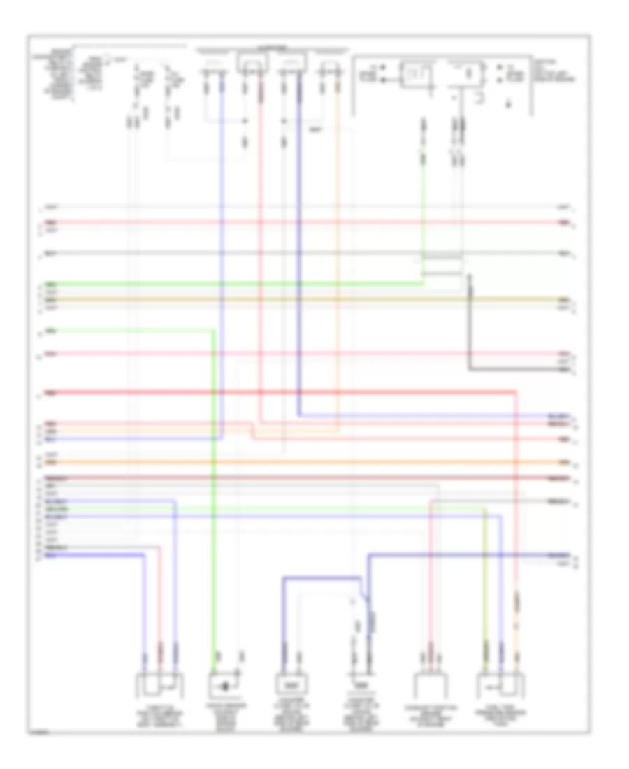
2.0L, Engine Performance Wiring Diagram (1 of 3) for Hyundai Elantra GT 2005

List of elements for 2.0L, Engine Performance Wiring Diagram (1 of 3) for Hyundai Elantra GT 2005:
- (left front of engine) engine coolant temperature sensor & sender
- (lower left side of dash) g169
- Abs control module (in right front corner of engine compt)
- Batt voltage
- Battery volt
- Battery voltage
- Canister purge valve (on left rear of engine compt, on bracket)
- Comm area network hi
- Comm area network lo
- Cpv ctrl
- Crankshaft position sensor (on left rear of engine)
- Ec03
- Ec04
- Emo2
- Engine compartment relay & fuse box (in left front corner of engine compt)
- Engine control relay
- Fuel pump motor
- Fuel pump relay
- Fuel sender & fuel pump motor (fuel sender: inside top of fuel tank) (fuel pump motor: below center of rear seat)
- Fusible link (ecu) 20a
- G04 (at middle front of rear seat cushion, under carpet)
- Gnd
- Ground
- Heated oxygen sensor (down) (below exhaust manifold)
- Heated oxygen sensor (up) (on front exhaust pipe, between catalytic converters)
- Hot at all times
- Htr
- Ign coil 1 (cyl 1,4)
- Ign coil 2 (cyl 2,3)
- Inj 1 ctrl
- Inj 4 ctrl
- Instrument cluster system
- Ip (+)
- Joint connector c191 (lower right side of dash)
- Joint connector e57
- Joint connector e58
- Nca
- Ocv
- Oil control valve (left front of engine)
- On/start in
- Oxygen sens heating
- Oxygen sens sig
- Pcm (left side of dash)
- Pnk
- Red
- Right front wheel sensor (w/o abs) (on right front hub assembly)
- Sensor ground
- Sensor pwr
- Sensor sig
- To inj fuse (diagram 2 of 3)
- Vehicle speed in
- Vs (+)
- Vs (-) ip (-)
- Wheel speed input
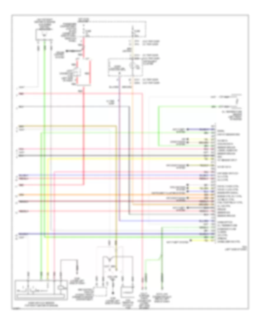
2.0L, Engine Performance Wiring Diagram (2 of 3) for Hyundai Elantra GT 2005
List of elements for 2.0L, Engine Performance Wiring Diagram (2 of 3) for Hyundai Elantra GT 2005:
- Camshaft position sensor (on right front of engine)
- Canister close valve (4door) (behind left side of rear bumper)
- Canister close valve (5door) (behind left side of rear bumper)
- Ec03
- Ec05
- Engine compartment relay & fuse box (in left front corner of engine compt)
- From a engine control relay (diagram 1 of 3)
- Fuel tank pressure sensor (above fuel tank)
- Ignition coil (on top left side of engine)
- Inj fuse 15a
- Injectors
- Knock sensor (on right side of engine block)
- Nca
- Pnk
- Red
- Snsr fuse 10a
- Throttle position sensor (on throttle body assembly)
- To spark plugs
2.0L, Engine Performance Wiring Diagram (3 of 3) for Hyundai Elantra GT 2005
List of elements for 2.0L, Engine Performance Wiring Diagram (3 of 3) for Hyundai Elantra GT 2005:
- (on top right center of engine) idle speed control actuator
- (w/ trip comp)
- (w/o trip comp)
- A/c relay ctrl
- A/c sig in
- A/c sw on in
- A/t
- Abs control module (in right front corner of engine compartment)
- Air conditioning system
- Anti-theft system
- Can line tool
- Can resistor (without tcs)
- Ccv ctrl
- Closing
- Consumption
- Cooling fans system
- Cooling sig in
- Cruise control system
- Data link connector (dlc) (below left side of dash)
- Diagnosis k-line
- E37
- Engine ctrl rly ctrl
- Engine rpm signal
- Fan rly (high) ctrl
- Fan rly (low) ctrl
- Fuel pump relay ctrl
- Fuse 10a
- G169 (lower left side of dash)
- Gnd
- Ground
- Hot in on or start
- I/p-h
- Iat sensor input
- Immobilizer ind ctrl
- Inj 2 ctrl
- Inj 3 ctrl
- Instrument cluster
- Instrument cluster system
- Joint connector c192 (left side of dash)
- Linear lambda rc
- M/t
- M09-1
- M09-2
- M10-1
- Maf mass air flow
- Maf/iat sensor gnd
- Mass air flow sensor (top right center of engine)
- Micro controller
- Mil ind
- Mil ind ctrl
- Multi- purpose check connector (lower left side of dash)
- Nca
- Oil temperature
- Oil temperature sensor (left front of engine)
- Opening
- Passenger compartment junction block (under left side of dash, near kick panel)
- Pcm (left side of dash)
- Pnk
- Red
- Sensor ground
- Sensor sig
- Signal
- W/ trip comp