ENGINE PERFORMANCE
3.8L
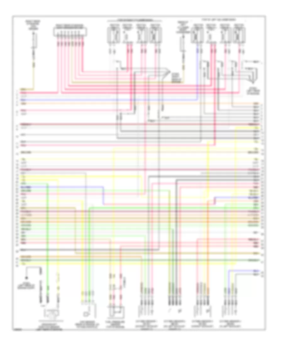
3.8L, Engine Performance Wiring Diagram (1 of 6) for Hyundai Genesis 3.8 2014

List of elements for 3.8L, Engine Performance Wiring Diagram (1 of 6) for Hyundai Genesis 3.8 2014:
- (left rear of engine compt) glg01
- (under left side of rear seat, in fuel tank)
- A/c pressure transducer (left front of engine compt)
- A/c relay control
- A/c request switch
- Air conditioning system
- Alt fr signal
- Aps 1 power
- Aps 1 signal
- Brake lamp
- Brake switch
- C-can hi
- C-can lo
- Ccp-can hi
- Ccp-can lo
- Clginj-b
- Cluster fuse 10a
- Computer data lines system
- E/r fuse & relay box (left front of engine compt)
- Ec21
- Ecm (left rear of engine compt)
- Ef11
- Elg-a
- Em31
- Engine check ind
- Exterior lights system
- Ftps signal
- Fuel level sensor 1 sig
- Fuel level snsr 2 sig
- Fuel pressure sensor (top of engine)
- Fuel pressure snsr gnd
- Fuel pressure snsr sig
- Fuel pump motor
- Fuel pump register relay
- Fuel register
- Fuel sender
- Fuel sender & fuel pump motor
- Fuel tank pressure sensor (rear of vehicle)
- Gf03 (left "c" pillar)
- Glg01 (left rear of engine compt)
- Gnd
- Ground
- Head lamp input
- Headlights system
- Hot at all times
- Hot in on or start
- I/p-lhe
- I/p-lhf
- Immo ind
- Indicators ctrl engine ck
- Indicators ctrl immo
- Instrument cluster
- Instrument cluster system
- Left i/p junction box (left end of dash)
- M11-a
- Memory power
- Module 3 fuse 10a
- Nca
- On/start input
- Pnk
- Power steering sensor (lower right front of engine)
- Pwr st snsr sig
- Red
- Sensor power (apt/fpt)
- Starting/charging system
- W/o button start
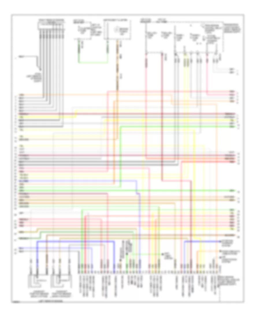
3.8L, Engine Performance Wiring Diagram (2 of 6) for Hyundai Genesis 3.8 2014
List of elements for 3.8L, Engine Performance Wiring Diagram (2 of 6) for Hyundai Genesis 3.8 2014:
- (not used)
- Accel pedal position sensor (behind accelerator pedal assembly)
- Alt c-terminal input
- Anti-theft system
- Aps 1 ground
- Aps 2 ground
- Aps 2 power
- Aps 2 signal
- Apt ground
- Apt signal
- Auto cruise switch gnd
- Auto cruise switch sig
- Ccv signal
- Cooling fan relay ctrl
- Cooling fans system
- Cruise control system
- Distribution system
- E/r-ca
- E/r-cb
- E/r-e1a
- E/r-e2a
- E/r-e2b
- Ec21
- Ecm (left rear of engine compt)
- Ecu (b+) fuse 15a
- Ecu (ig1) fuse 10a
- Ecu fuse 30a
- Elg-a
- Em21
- Engine control relay
- Engine ctrl relay 'on' in
- Engine ctrl relay ctrl
- Engine room junction box (right rear of engine compt)
- Engine rotation signal
- F/pump fuse 20a
- Fuel pump relay
- Fuel pump relay ctrl
- Fuel resistor relay ctrl
- Fuel tank pr snsr gnd
- Fuel tank pr snsr pwr
- Glg01 (left rear of engine compt)
- Ground
- Hot at all times
- Hot in on or start
- Immo signal
- Immobilizer module (left side of dash)
- Lin communication
- Memory power
- Pnk
- Power
- Red
- Snsr 2 fuse 10a
- Snsr 3 fuse 10a
- Start relay ctrl
- Starting/ charging system
- To ign coil 1 (diagram 6 of 6)
- To injector (b+) fuse (diagram 5 of 6)
- To oil control valve (diagram 6 of 6)
- To snsr 1 fuse (diagram 6 of 6)
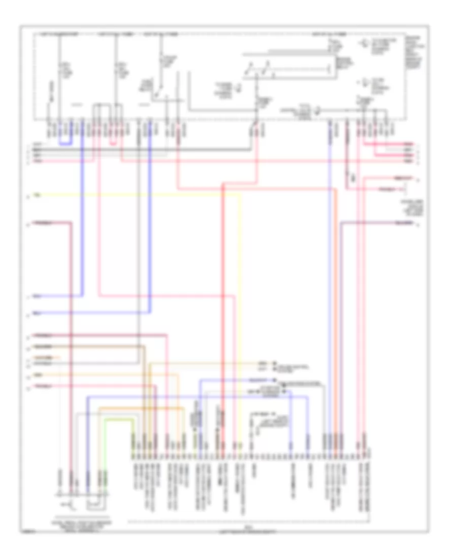
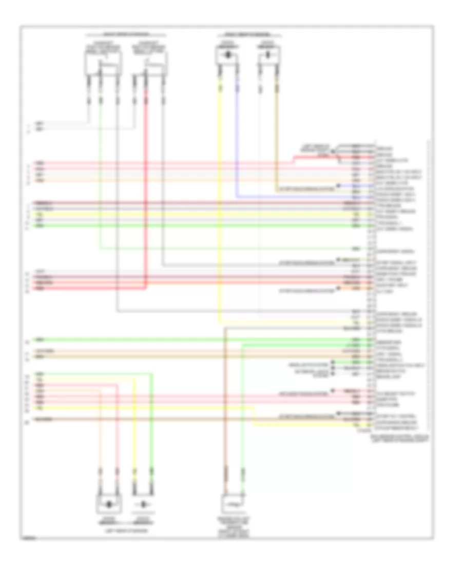
3.8L, Engine Performance Wiring Diagram (3 of 6) for Hyundai Genesis 3.8 2014
List of elements for 3.8L, Engine Performance Wiring Diagram (3 of 6) for Hyundai Genesis 3.8 2014:
- (left rear of engine)
- (lower left rear of engine) crankshaft position sensor
- (rear of intake manifold) purge control solenoid valve
- (rear of vehicle) canister close valve
- (right rear of engine)
- (right rear of engine) j/c jca
- (top right front of engine) variable intake manifold valve
- (top right rear of engine) oil temperature sensor
- Camshaft position sensor (bank 1 exhaust)
- Camshaft position sensor (bank 1 intake)
- Camshaft position sensor (bank 2 exhaust)
- Camshaft position sensor (bank 2 intake)
- Ef11
- Knock sensor 1 (right front of engine)
- Knock sensor 2 (left front of engine)
- Nca
- Pnk
- Red
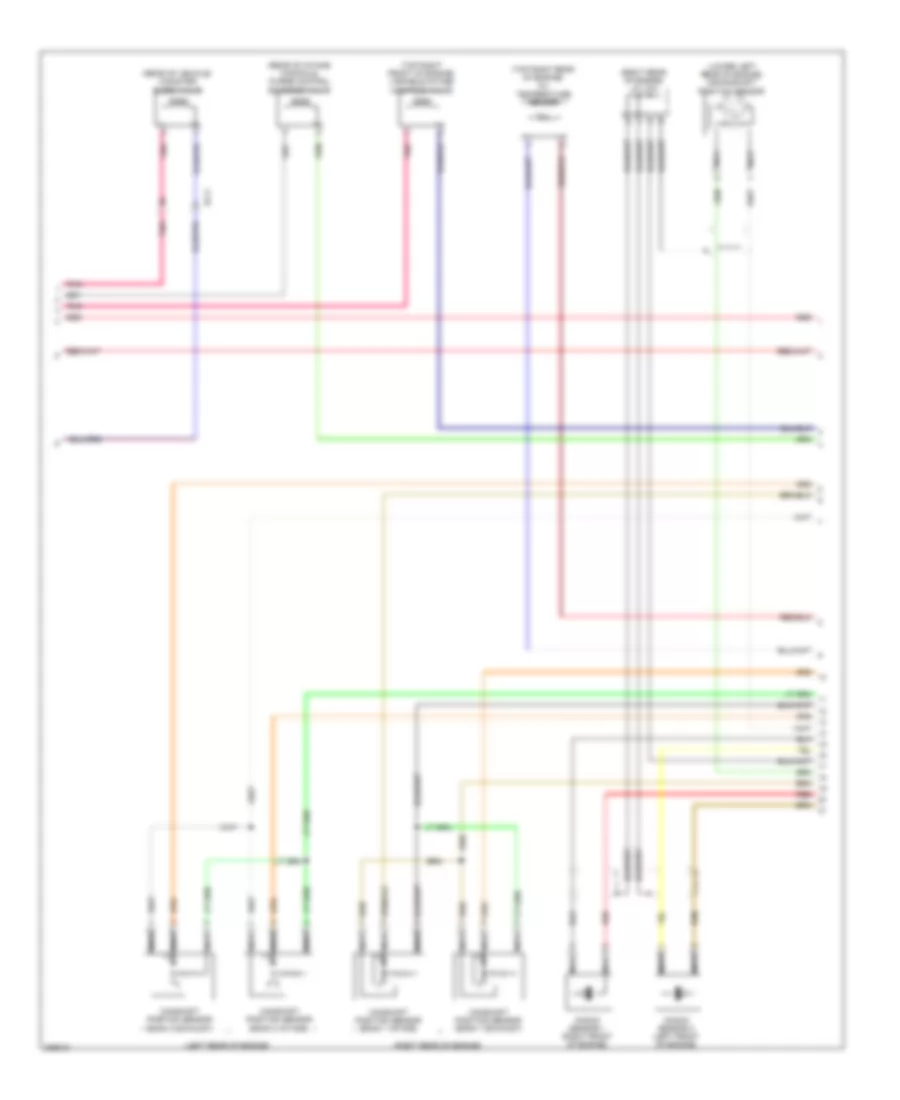
3.8L, Engine Performance Wiring Diagram (4 of 6) for Hyundai Genesis 3.8 2014
List of elements for 3.8L, Engine Performance Wiring Diagram (4 of 6) for Hyundai Genesis 3.8 2014:
- (air filter housing) barometric pressure sensor
- (left rear of engine compt) glg01
- (rear of engine, on intake manifold) map sensor
- (right rear of engine compt) engine room junction box
- (right rear of engine) engine coolant temperature sensor
- (right rear of engine) j/c jca
- Air temp snsr (exhaust)
- Anti-lock brakes system
- Ckps hi
- Ckps lo
- Clg-bg
- Cmps bank 1 (exhaust) sig
- Cmps bank 1 ground
- Cmps bank 2 ground
- Cmps bank2 (intake) sig
- Cmps power
- Crank request
- E/r-cb
- Ecm (left rear of engine compt)
- Etc motor & throttle position sensor (on throttle body)
- Glg01 (left rear of engine compt)
- Glg02
- Ground
- Ignition coil 1 control
- Ignition coil 3 control
- Knock sensor 1 hi
- Knock sensor 1 lo
- Knock sensor 2 hi
- Knock sensor 2 lo
- Map signal
- Motor
- Oil temp sensor ground
- Oxygen sensor 1 hi
- Oxygen sensor 1 lo
- Oxygen sensor 4 lo
- Pnk
- Red
- Sensor 1
- Sensor 2
- Sensor power (baro/map)
- Sensor signal
- Shield ground
- Starting/ charging system
- Throttle position sensor
- Tps ground
- Tps power
- Vehicle speed snsr in
- Wts signal
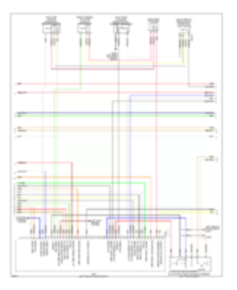
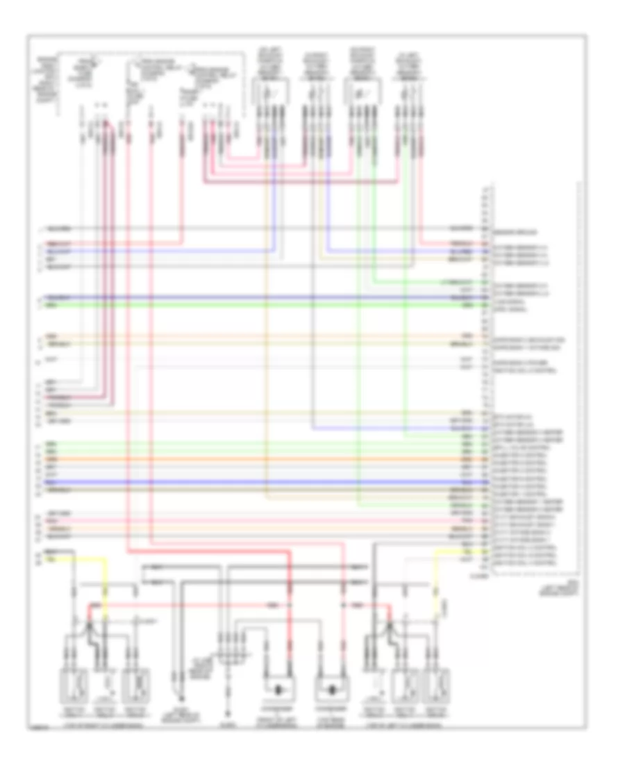
3.8L, Engine Performance Wiring Diagram (5 of 6) for Hyundai Genesis 3.8 2014
List of elements for 3.8L, Engine Performance Wiring Diagram (5 of 6) for Hyundai Genesis 3.8 2014:
- (left rear of engine compt) injector drive box
- (left rear of engine) j/c jcc
- C-can high
- C-can low
- Ciginj-a
- Clgocv
- Computer data lines system
- Ctginj-b
- E/r-cb
- Engine ctrl rly on in
- Engine room junction box (right rear of engine compt)
- From a engine control relay (diagram 2 of 6)
- Glg01 (left rear of engine compt)
- Ground
- Hot in on or start
- Injector (b+) fuse 15a
- Injector (ig1) fuse 10a
- Injector 1 high
- Injector 1 low
- Injector 2 high
- Injector 2 low
- Injector 3 high
- Injector 3 low
- Injector 4 high
- Injector 4 low
- Injector 5 high
- Injector 5 low
- Injector 6 high
- Injector 6 low
- Injectors (top of left cylinder bank)
- Injectors (top of right cylinder bank)
- Logic input inj1
- Logic input inj2
- Logic input inj3
- Logic input inj4
- Logic input inj5
- Logic input inj6
- Logic input spill valve
- Memory power
- Nca
- Oil control valve 1 (bank 1) (exhaust) (front of right cylinder head)
- Oil control valve 2 (bank 2) (exhaust) (front of left cylinder head)
- Oil control valve 3 (bank 1) (intake) (front of right cylinder head)
- Oil control valve 4 (bank 2) (intake) (front of left cylinder head)
- On/start input
- Pnk
- Red
- Spill valve (top of left cylinder head)
- Spill valve high
- Spill valve low
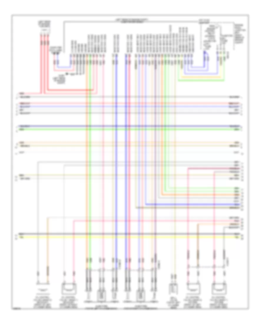
3.8L, Engine Performance Wiring Diagram (6 of 6) for Hyundai Genesis 3.8 2014
List of elements for 3.8L, Engine Performance Wiring Diagram (6 of 6) for Hyundai Genesis 3.8 2014:
- (in left exhaust) oxygen sensor 4 (b2/s2)
- (in right exhaust) oxygen sensor 3 (b1/s2)
- (on left exhaust manifold) oxygen sensor 1 (b1/s1)
- (on right exhaust manifold) oxygen sensor 2 (b2/s1)
- (right
- (top of left cylinder bank)
- (top of right cylinder bank)
- Box
- Clg-bg
- Clgig-1
- Clgig-2
- Cmps bank 1 (intake) sig
- Cmps bank 2 (exhaust) sig
- Cmps bank 2 power
- Condenser (front of left cylinder bank)
- Condenser (top rear of engine)
- Cpsv signal
- Cvvt (exhaust) bank 1
- Cvvt (exhaust) bank 2
- Cvvt (intake) bank 1
- Cvvt (intake) bank 2
- E/r-ca
- E/r-cb
- E/r-e2a
- Ecm (left rear of engine compt)
- Engine
- Engine compt)
- Etc motor (hi)
- Etc motor (lo)
- From b snsr 2 fuse (diagram 2 of 6)
- From engine control relay (diagram 2 of 6)
- Glg01 (left rear of engine compt)
- Glg02
- Ign coil 1 fuse 20a
- Ignition coil 1
- Ignition coil 2
- Ignition coil 2 control
- Ignition coil 3
- Ignition coil 4
- Ignition coil 4 control
- Ignition coil 5
- Ignition coil 5 control
- Ignition coil 6
- Ignition coil 6 control
- Inject0r 1 control
- Inject0r 2 control
- Inject0r 3 control
- Inject0r 4 control
- Inject0r 5 control
- Inject0r 6 control
- J/c jcb (right rear of engine)
- Junction
- Nca
- Oxygen sensor 1 heater
- Oxygen sensor 2 heater
- Oxygen sensor 2 hi
- Oxygen sensor 2 lo
- Oxygen sensor 3 heater
- Oxygen sensor 3 hi
- Oxygen sensor 3 lo
- Oxygen sensor 4 heater
- Oxygen sensor 4 hi
- Pnk
- Rear of
- Red
- Room
- Sensor ground
- Snsr 1 fuse 10a
- Spill valve control
- Vics signal
5.0L
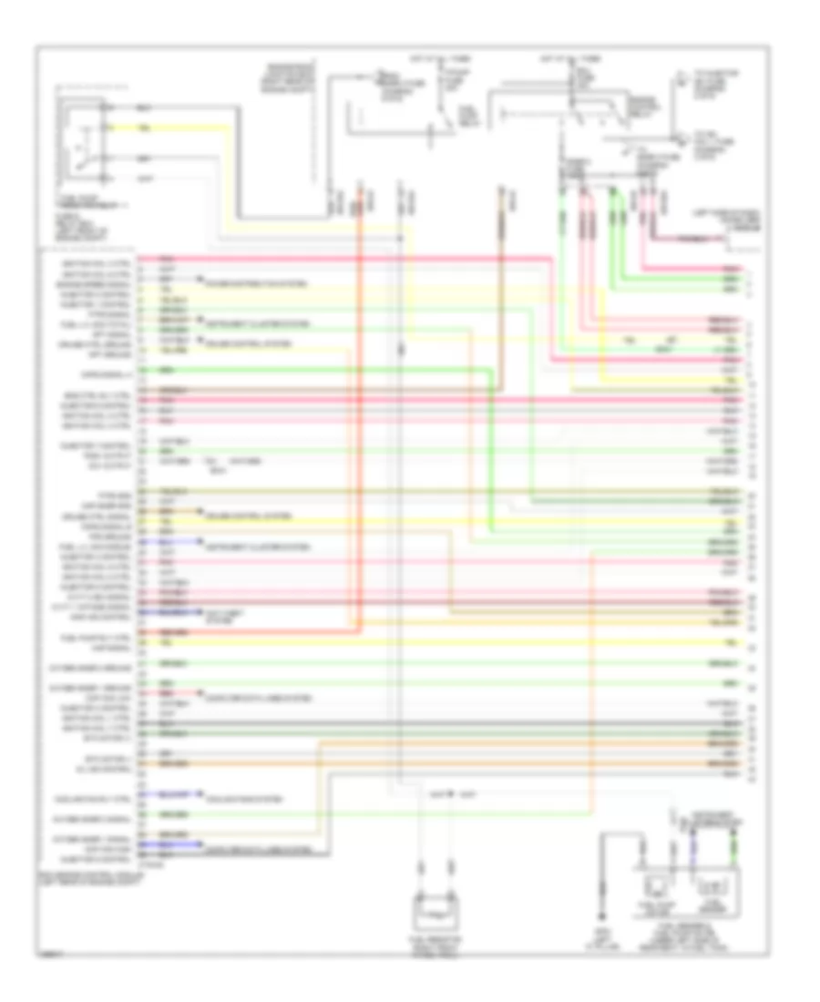
5.0L, Engine Performance Wiring Diagram (1 of 6) for Hyundai Genesis 3.8 2014
List of elements for 5.0L, Engine Performance Wiring Diagram (1 of 6) for Hyundai Genesis 3.8 2014:
- (left side of dash) immobilizer module
- Anti-theft system
- Apt ground
- Apt signal
- Ccp can high
- Ccp can low
- Ccv output
- Ckps signal a
- Ckps signal b
- Computer data lines system
- Cooling fan rly ctrl
- Cooling fans system
- Cruise control system
- Cruise ctrl ground
- Cruise ctrl signal
- Ctg-ag
- Cvvt 1 (intake) signal
- Cvvt 2 (ex) signal
- E/r-ca
- E/r-cb
- E/r-e1a
- E/r-e2a
- Ec41
- Ecm (engine control module) (left rear of engine compt)
- Ecu fuse 30a
- Ef11
- Eng ctrl rly ctrl
- Engine control relay
- Engine room junction box (right rear of engine compt)
- Engine speed signal
- Etc motor (+)
- Etc motor (-)
- F/pump fuse 20a
- Fps ground
- From snsr 3 fuse (diagram 5 of 6)
- Ftps gnd
- Ftps signal
- Fuel lvl sig (middle)
- Fuel lvl sig (total)
- Fuel pump motor
- Fuel pump relay
- Fuel pump resistor relay
- Fuel pump rly ctrl
- Fuel resistor (right front wheel well)
- Fuel sender
- Fuel sender & fuel pump motor (under left side of rear seat, in fuel tank)
- Fuse & relay box (left front of engine compt)
- Gf03 (left "c" pillar)
- Hot at all times
- Ignition coil 1 ctrl
- Ignition coil 2 ctrl
- Ignition coil 3 ctrl
- Ignition coil 4 ctrl
- Ignition coil 5 ctrl
- Ignition coil 6 ctrl
- Ignition coil 7 ctrl
- Ignition coil 8 ctrl
- Immo ind control
- Injector 1 control
- Injector 2 control
- Injector 3 control
- Injector 4 control
- Injector 5 control
- Injector 6 control
- Injector 7 control
- Injector 8 control
- Instrument cluster system
- Map signal
- Map snsr gnd
- Mil ind control
- Oxygen snsr 1 ground
- Oxygen snsr 1 signal
- Oxygen snsr 2 ground
- Oxygen snsr 2 signal
- Pcsv output
- Pnk
- Power distribution system
- Red
- Snsr 2 fuse 10a
- To ign coil 1 fuse (diagram 3 of 6)
- To injector (b+) fuse (diagram 2 of 6)
- To snsr 3 fuse (diagram 5 of 6)
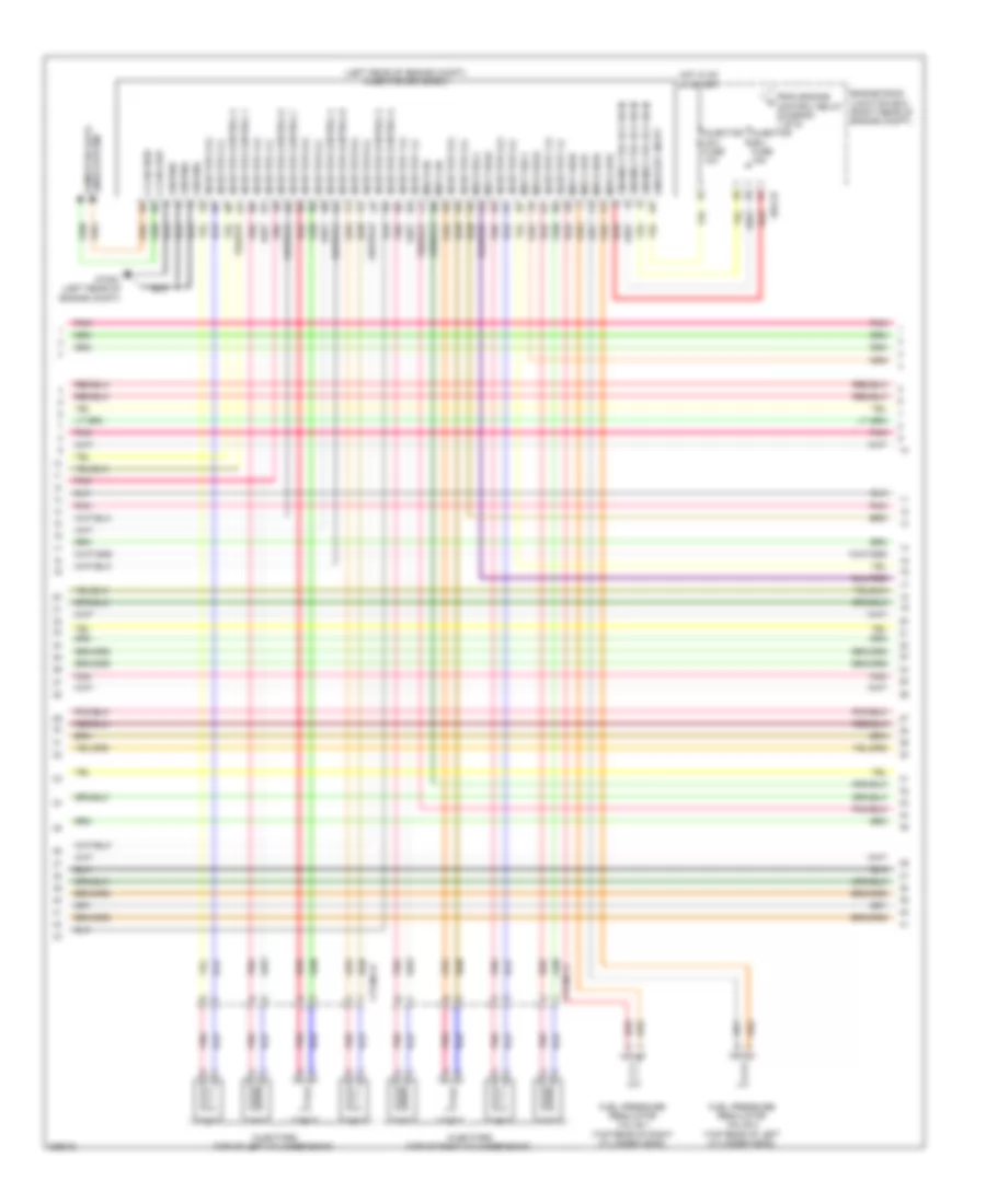
5.0L, Engine Performance Wiring Diagram (2 of 6) for Hyundai Genesis 3.8 2014
List of elements for 5.0L, Engine Performance Wiring Diagram (2 of 6) for Hyundai Genesis 3.8 2014:
- (left rear of engine compt) injector drive box
- C-can high
- C-can low
- Computer data lines system
- Ctginj-a
- Ctginj-b
- E/r-cb
- Engine ctrl rly on in
- Engine room junction box (right rear of engine compt)
- From engine control relay (diagram 1 of 6)
- Fuel pressure regulator valve 1 (top rear of right cylinder head)
- Fuel pressure regulator valve 2 (top rear of left cylinder head)
- Ground
- Gtg01 (left rear of engine compt)
- Hot in on or start
- Injector (b+) fuse 15a
- Injector (ig1) fuse 10a
- Injector 1 (+)
- Injector 1 (-)
- Injector 2 (+)
- Injector 2 (-)
- Injector 3 (+)
- Injector 3 (-)
- Injector 4 (+)
- Injector 4 (-)
- Injector 5 (+)
- Injector 5 (-)
- Injector 6 (+)
- Injector 6 (-)
- Injector 7 (+)
- Injector 7 (-)
- Injector 8 (+)
- Injector 8 (-)
- Injector control 1
- Injector control 2
- Injector control 3
- Injector control 4
- Injector control 5
- Injector control 6
- Injector control 7
- Injector control 8
- Injectors (top of left cylinder bank)
- Injectors (top of right cylinder bank)
- Msv1 high
- Msv1 low
- Msv1 on
- Msv1 sel0
- Msv1 sel1
- Msv2 high
- Msv2 low
- Msv2 on
- Msv2 sel0
- Msv2 sel1
- On/start input
- Pnk
- Red
5.0L, Engine Performance Wiring Diagram (3 of 6) for Hyundai Genesis 3.8 2014
List of elements for 5.0L, Engine Performance Wiring Diagram (3 of 6) for Hyundai Genesis 3.8 2014:
- (front of left cylinder head)
- (front of right cylinder head)
- (rear of intake manifold) purge control solenoid valve
- (rear of vehicle) canister close valve
- 1 of 6)
- A/c pressure transducer (left front of engine compt)
- Accel pedal position sensor (behind accelerator pedal assembly)
- Control relay (diagram
- E/r-ca
- E/r-cb
- E/r-e2a
- Ec41
- Ef11
- Engine room junction box (right rear of engine compt)
- Etc motor & throttle position sensor (on throttle body)
- From engine b
- Fuel tank pressure sensor (rear of vehicle)
- Ign coil 1 fuse 20a
- Motor
- Oil control valve 1 (intake)
- Oil control valve 2 (exhaust)
- Oil control valve 3 (intake)
- Oil control valve 4 (exhaust)
- Pnk
- Red
- Throttle position sensor
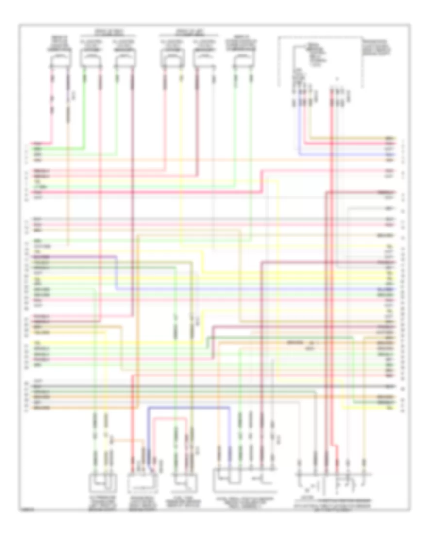
5.0L, Engine Performance Wiring Diagram (4 of 6) for Hyundai Genesis 3.8 2014
List of elements for 5.0L, Engine Performance Wiring Diagram (4 of 6) for Hyundai Genesis 3.8 2014:
- (rear of left cylinder bank) condenser
- (right rear of engine) con- denser
- (right rear of engine) joint connector jcb
- (top of left cylinder bank)
- (top of right cylinder bank)
- Crankshaft position sensor (left rear of engine)
- Ctginj-a
- Fuel pressure sensor (top of engine)
- Gtg01 (left rear of engine compt)
- Gtg02 (right rear of engine)
- Gtg03 (left rear of engine)
- Ignition coil 1
- Ignition coil 2
- Ignition coil 3
- Ignition coil 4
- Ignition coil 5
- Ignition coil 6
- Ignition coil 7
- Ignition coil 8
- Map sensor (rear of engine, on intake manifold)
- Nca
- Oxygen sensor 1 (b1/s1) (on right exhaust manifold)
- Oxygen sensor 2 (b2/s1) (on left exhaust manifold)
- Oxygen sensor 3 (b1/s2) (in right exhaust)
- Oxygen sensor 4 (b2/s2) (in left exhaust)
- Pnk
- Red
5.0L, Engine Performance Wiring Diagram (5 of 6) for Hyundai Genesis 3.8 2014
List of elements for 5.0L, Engine Performance Wiring Diagram (5 of 6) for Hyundai Genesis 3.8 2014:
- (left rear of engine)
- (right rear of engine) j/c jca
- A/c comp output
- Air conditioning system
- Alt fr
- Anti- theft system
- Apm 1 ground
- Apm 2 ground
- Apm 2 signal
- Brakes system anti-lock
- Camshaft position sensor (bank 2 exhaust)
- Camshaft position sensor (bank 2 intake)
- Can high
- Can low
- Check ind
- Cluster fuse 10a
- Cmps bank1 signal
- Cmps bank2 ground
- Cmps bank2 signal
- Computer data lines system
- Ctg-kg
- Cvvt 3 signal
- Cvvt 4 signal
- E/r-ca
- E/r-cb
- Ec41
- Ecm (engine control module) (left rear of engine compt)
- Ecu (b+) fuse 10a
- Ecu (ig1) fuse 10a
- Em31
- Engine
- Engine room junction box (right rear of engine compt)
- From engine control relay (diagram 1 of 6)
- Gtg01 (left rear of of engine compt)
- Hot at all times
- Hot in on or start
- I/p-lhe
- Immo sig
- Instrument cluster
- Knock snsr 2 sig a
- Knock snsr 2 sig b
- Knock snsr 4 sig a
- Knock snsr 4 sig b
- Left i/p junction box (left end of dash)
- M11-a
- Memory power
- Msv 1 on
- Msv 1 sel0
- Msv 1 sel1
- Msv 2 on
- Msv 2 sel0
- Msv 2 sel1
- Nca
- Oxy snsr 1 htr
- Oxy snsr 3 htr
- Oxy snsr 3 signal
- Oxy snsr 4 ground
- Pnk
- Red
- Snsr 1 fuse 10a
- Snsr 3 fuse 10a
- Starting/ charging system
- To fuel pump relay (diagram 1 of 6)
- Veh spd sig
5.0L, Engine Performance Wiring Diagram (6 of 6) for Hyundai Genesis 3.8 2014
List of elements for 5.0L, Engine Performance Wiring Diagram (6 of 6) for Hyundai Genesis 3.8 2014:
- (left rear of engine compt) gtg01
- (left rear of engine)
- (right rear of engine)
- A/c select switch
- Air conditioning system
- Alt com
- Apm 1 power
- Apm 1 signal
- Brake lamp
- Brake switch
- Camshaft position sensor (bank 1 exhaust)
- Camshaft position sensor (bank 1 intake)
- Cmps bank1 ground
- Cmps bank1 signal
- Cmps bank2 ground
- Ctg-kg
- Ecm (engine control module (left rear of engine compt)
- Eng ctrl rly on input
- Engine coolant temperature sensor (front of right cylinder head)
- Exterior lights system
- F/pump resister rly
- Fps power
- Fps signal
- Ground
- Headlamp switch input
- Headlights system
- Knock sensor 1
- Knock sensor 2
- Knock sensor 3
- Knock sensor 4
- Knock snsr 1 sig a
- Knock snsr 1 signal b
- Knock snsr 3 sig a
- Knock snsr 3 signal b
- Lin communication
- Nca
- On/start input
- Oxy snsr 2 htr
- Oxy snsr 3 ground
- Oxy snsr 3 htr
- Oxy snsr 4 signal
- Pnk
- Red
- Sensor gnd
- Snsr pwr
- Snsr pwr (tps/map)
- Start rly control
- Start signal input
- Starting/charging system
- Tps ground
- Tps signal 1
- Tps signal 2
- Wts ground
- Wts signal