ENGINE PERFORMANCE
2.7L
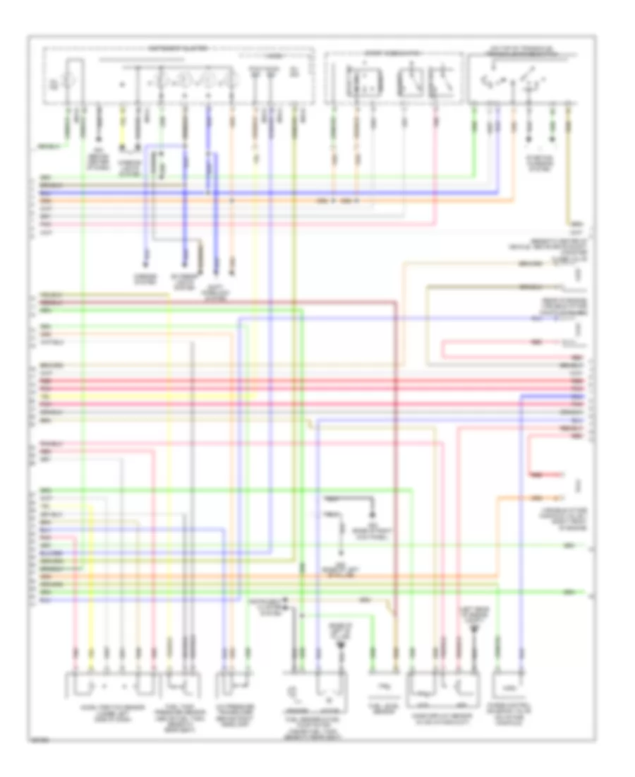
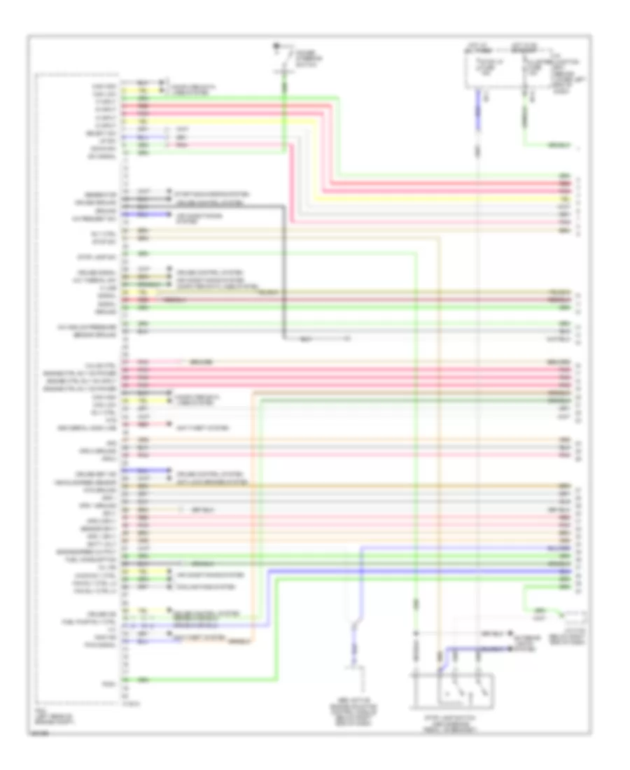
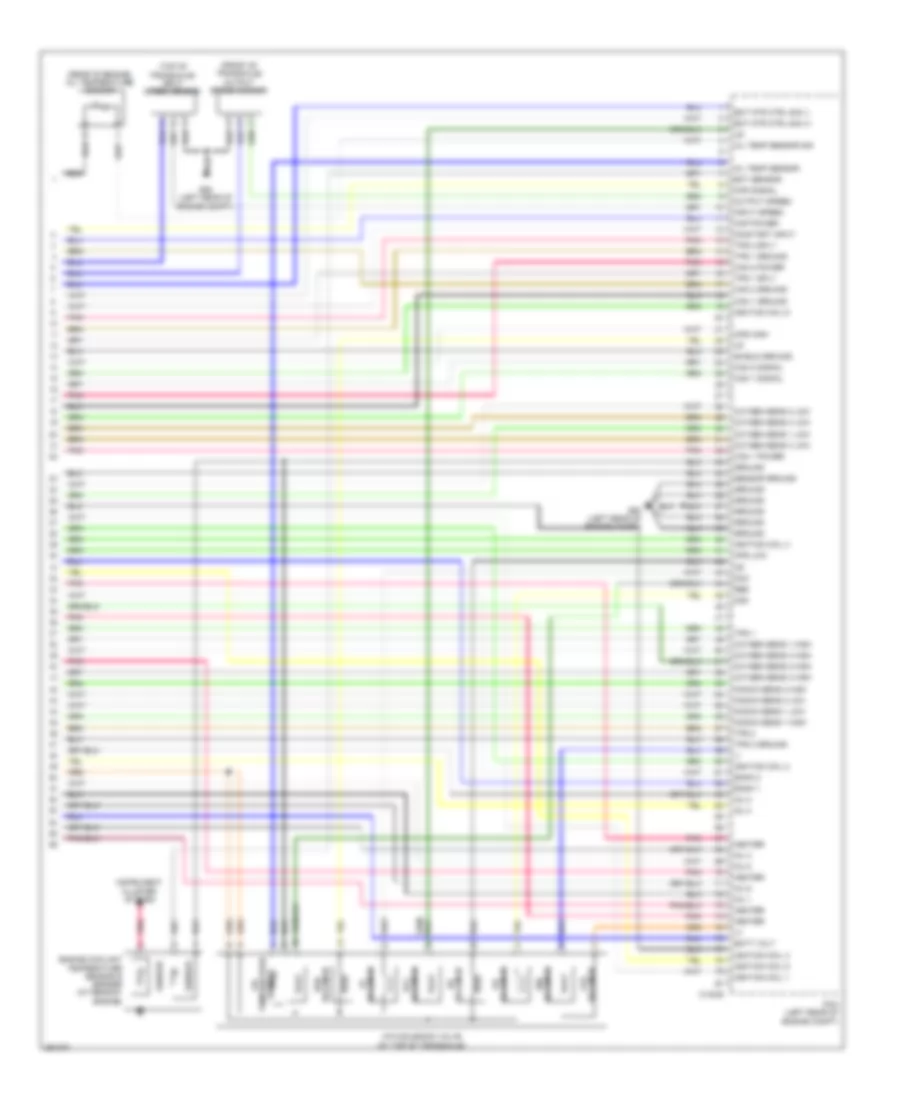
2.7L, Engine Performance Wiring Diagram (1 of 5) for Hyundai Santa Fe GLS 2008

List of elements for 2.7L, Engine Performance Wiring Diagram (1 of 5) for Hyundai Santa Fe GLS 2008:
- A/c analog pressure
- A/c request sw
- A/c thermal sw
- A/con rly ctrl
- A/t
- Afs
- Air conditioning system
- Anti-lock brakes system
- Anti-theft system
- Aps 1
- Aps 1 ground
- Aps 1 sply
- Aps 2
- Aps 2 ground
- Aps 2 sply
- Ats
- Ats ground
- Batt volt
- C30-a
- Can high
- Can low
- Cluster fuse 10a
- Clutch sw
- Clutch switch (m/t) (above clutch pedal, on bracket)
- Computer data lines system
- Cooling fans system
- Cruise control system
- Cruise ground
- Cruise ind
- Cruise set ind
- Cruise signal
- D input
- Down shift
- Engine ctrl rly on input
- Engine ctrl rly on power
- Engine speed output
- Exterior lights system
- Fan rly ctrl hi
- Fan rly ctrl lo
- Fuel chk 1
- Fuel consumption
- Fuel pump rly ctrl
- Generator
- Ground
- Hot at all times
- Hot in on or start
- I/p junction box (behind lower left end of dash)
- I/p-j
- I/p-k
- Immo ind
- Immo serial comm line
- J/c c23 (top left side of engine)
- K line
- Mil ind
- N input
- P input
- Pcm (left rear of engine compt)
- Pcsv
- Pnk
- Power steering switch (on top of power steering pump, on front of engine)
- Pwm signal
- R input
- Red
- Rly ctrl
- Select sw
- Semi active engine mounting control module (below right end of dash)
- Sensor ground
- Sensor sply
- Signal
- Sply
- Starting/charging system
- Stop lamp sw
- Stop lamp switch (above brake pedal, on bracket)
- Stop lp fuse 15a
- Stop sw
- Sw signal
- Up shift
- Valve ctrl
- Vehicle speed sensor
- Viv 1
- Viv 2
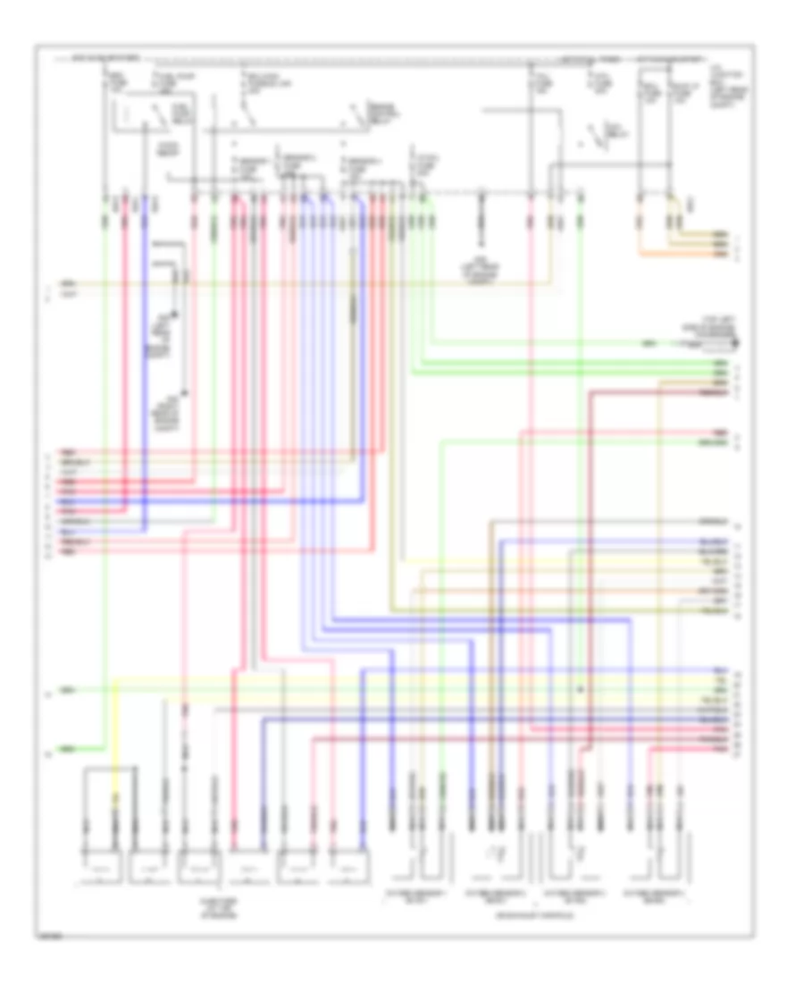
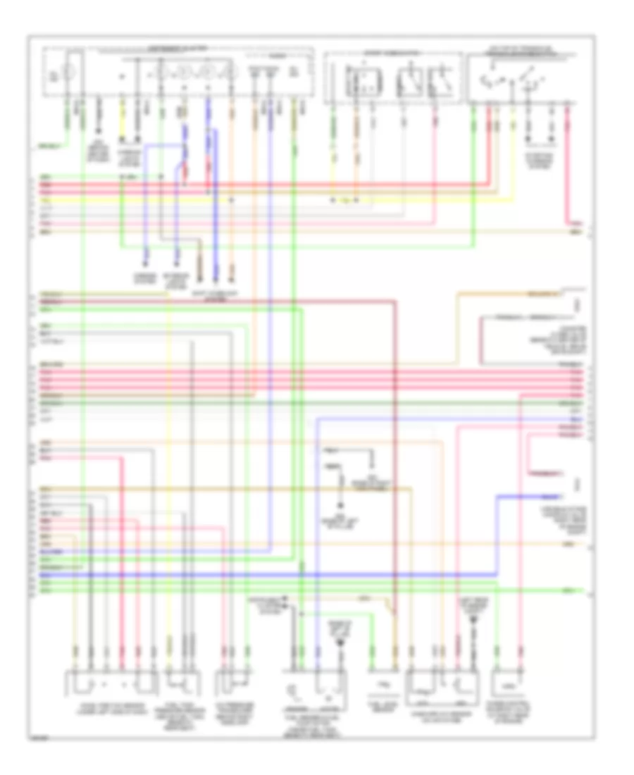
2.7L, Engine Performance Wiring Diagram (2 of 5) for Hyundai Santa Fe GLS 2008
List of elements for 2.7L, Engine Performance Wiring Diagram (2 of 5) for Hyundai Santa Fe GLS 2008:
- (base of left "b" pillar) g05
- (beneath center of vehicle, above drive shaft) canister close valve
- (left rear of engine compt) g39
- (on top of transaxle) transaxle range switch
- (rear of engine) variable intake manifold valve 2
- A/c pressure transducer (behind right headlamp)
- Accel position sensor (under left side of dash)
- Afs
- Ats
- Down shift
- Exterior lights system
- Fuel level sensor
- Fuel sender & fuel pump motor (inside fuel tank, beneath rear seat)
- Fuel tank pressure sensor (above fuel tank, beneath rear seat)
- G02 (base of right kick panel)
- G05 (base of left "b" pillar)
- G33 (behind center of dash)
- Inj sig
- Instrument cluster
- Instrument cluster system
- Interior lights system
- M15-a
- M15-b
- M15-d
- Mass airflow sensor (in air intake duct)
- Micom
- Mil ind
- Mirrors system
- Motor
- Normal
- P r
- Pnk
- Purge control solenoid valve (on intake manifold)
- Pwm sig
- Red
- Select
- Select sw
- Sender
- Shift interlock system
- Sport mode switch
- Starting/ charging system
- Tacho sig
- Up shift
- Variable intake manifold valve 1 (right front of engine)
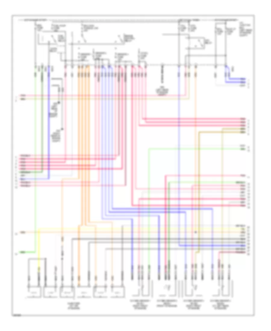
2.7L, Engine Performance Wiring Diagram (3 of 5) for Hyundai Santa Fe GLS 2008
List of elements for 2.7L, Engine Performance Wiring Diagram (3 of 5) for Hyundai Santa Fe GLS 2008:
- (on exhaust manifold)
- (top left side of engine) condenser
- A/con relay
- Atm fuse 20a
- Atm relay
- B/up lp fuse 10a
- Ecu fuse 10a
- Ecu main fusible link 40a
- Engine control relay
- Esc fuse 10a
- Fuel pump fuse 15a
- Fuel pump relay
- G38 (left rear of engine compt)
- G39 (left rear of engine compt)
- G40 (right rear of engine compt)
- Hot at all times
- Hot in on or start
- Ig coil fuse 20a
- Injectors (at top of engine)
- Nca
- Oxygen sensor 1 (b1/s1)
- Oxygen sensor 2 (b2/s1)
- Oxygen sensor 3 (b1/s2)
- Oxygen sensor 4 (b2/s2)
- Pnk
- Red
- Sensor 1 fuse 10a
- Sensor 2 fuse 15a
- Sensor 3 fuse 15a
- Tcu fuse 15a
- U/h junction box (left rear of engine compt)
- U/h-c
- U/h-u
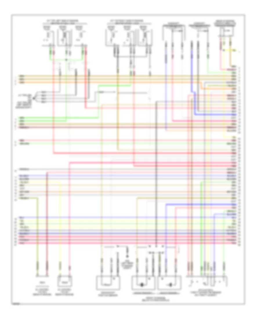
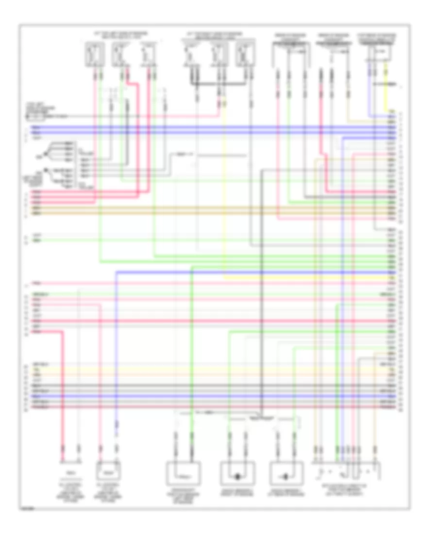
2.7L, Engine Performance Wiring Diagram (4 of 5) for Hyundai Santa Fe GLS 2008
List of elements for 2.7L, Engine Performance Wiring Diagram (4 of 5) for Hyundai Santa Fe GLS 2008:
- (at top left side of engine) ignition coils 2, 4 & 6
- (at top right side of engine) ignition coils 1, 3 & 5
- (front of engine, below intake manifold)
- (rear of engine) manifold absolute pressure sensor
- (w/ trailer) g41 g39 (w/o trailer) (left rear of engine compt)
- Camshaft position sensor 1
- Camshaft position sensor 2
- Crankshaft position sensor
- Etc motor & throttle position sensor (on throttle body)
- G39 (left rear of engine compt)
- Knock sensor 1
- Knock sensor 2
- Nca
- Oil control valve 1 (rear of engine)
- Oil control valve 2 (rear of engine)
- Pnk
- Red
- Spark plug
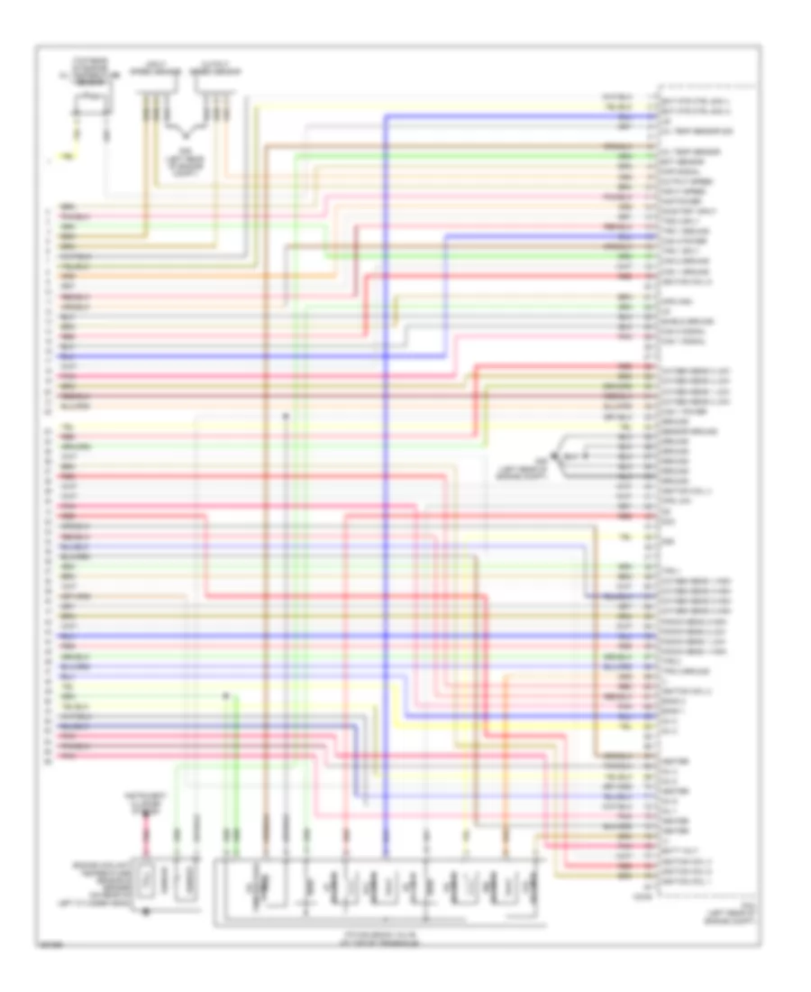
2.7L, Engine Performance Wiring Diagram (5 of 5) for Hyundai Santa Fe GLS 2008
List of elements for 2.7L, Engine Performance Wiring Diagram (5 of 5) for Hyundai Santa Fe GLS 2008:
- (+)
- (-)
- (top rear of engine) oil temperature sensor
- 2nd
- Atm solenoid valve (at top of transaxle)
- Bank 1
- Bank 2
- Batt volt
- C30-b
- Cam 1 ground
- Cam 1 power
- Cam 1 signal
- Cam 2 ground
- Cam 2 power
- Cam 2 signal
- Cps high
- Cps low
- Dcc
- Ect mtr ctrl sig (+)
- Ect mtr ctrl sig (-)
- Ect sensor
- Engine coolant temperature sensor & sender (on rear of left cylinder head)
- G39 (left rear of engine compt)
- Ground
- Heater
- Ignition coil 1
- Ignition coil 2
- Ignition coil 3
- Ignition coil 4
- Ignition coil 5
- Ignition coil 6
- Inj 1
- Inj 2
- Inj 3
- Inj 4
- Inj 5
- Inj 6
- Input speed
- Input speed sensor
- Instrument cluster system
- Knock sens 1 high
- Knock sens 1 low
- Knock sens 2 high
- Knock sens 2 low
- Map power
- Map signal
- Oil temp sensor
- Oil temp sensor sig
- On/start input
- Output speed
- Output speed sensor
- Oxygen sens 1 high
- Oxygen sens 1 low
- Oxygen sens 2 high
- Oxygen sens 2 low
- Oxygen sens 3 high
- Oxygen sens 3 low
- Oxygen sens 4 high
- Oxygen sens 4 low
- Pcm (left rear of engine compt)
- Pnk
- Red
- Sender
- Sensor
- Sensor ground
- Sensor temperature oil
- Shield ground
- Solenoid 2nd
- Solenoid dcc
- Solenoid lr
- Solenoid od
- Solenoid ud
- Tps 1
- Tps 1 ground
- Tps 1 sply
- Tps 2
- Tps 2 ground
- Tps 2 sply
- Vfs solenoid
3.3L
3.3L, Engine Performance Wiring Diagram (1 of 5) for Hyundai Santa Fe GLS 2008
List of elements for 3.3L, Engine Performance Wiring Diagram (1 of 5) for Hyundai Santa Fe GLS 2008:
- A/c analog pressure
- A/c request sw
- A/c thermal sw
- A/con rly ctrl
- Afs
- Air conditioning system
- Anti-lock brakes system
- Anti-theft system
- Aps 1
- Aps 1 ground
- Aps 1 sply
- Aps 2
- Aps 2 ground
- Aps 2 sply
- Ats
- Ats ground
- Batt volt
- C130-a
- Can high
- Can low
- Cluster fuse 10a
- Computer data lines system
- Cooling fans system
- Cruise control system
- Cruise ground
- Cruise ind
- Cruise set ind
- Cruise signal
- D input
- Down sw
- Engine ctrl rly on input
- Engine ctrl rly on power
- Engine speed output
- Exterior lights system
- Fan rly ctrl hi
- Fan rly ctrl lo
- Fuel consumption
- Fuel pump rly ctrl
- Generator
- Ground
- Hot at all times
- Hot in on or start
- I/p junction box (behind lower left end of dash)
- I/p-j
- I/p-k
- Immo ind
- Immo serial comm line
- J/c c123 (below right end of dash)
- K line
- Mil ind
- N input
- P input
- Pcm (left rear of engine compt)
- Pcsv
- Pnk
- Power steering switch
- Pwm signal
- R input
- Red
- Rly ctrl
- Select sw
- Semi active engine mounting control module (below right end of dash)
- Sensor ground
- Sensor sply
- Signal
- Sply
- Starting/charging system
- Stop lamp sw
- Stop lamp switch (above brake pedal, on bracket)
- Stop lp fuse 15a
- Stop sw
- Sw signal
- Up sw
- Valve ctrl
- Vehicle speed sensor
- Viv
3.3L, Engine Performance Wiring Diagram (2 of 5) for Hyundai Santa Fe GLS 2008
List of elements for 3.3L, Engine Performance Wiring Diagram (2 of 5) for Hyundai Santa Fe GLS 2008:
- (base of left "b" pillar) g05
- (left rear of engine compt) g52
- (on top of transaxle) transaxle range switch
- A/c pressure transducer (behind right headlamp)
- Accel position sensor (under left side of dash)
- Afs
- Ats
- Canister close valve (beneath center of vehicle, above drive shaft)
- Down shift
- Exterior lights system
- Fuel level sensor
- Fuel sender & fuel pump motor (inside fuel tank, beneath rear seat)
- Fuel tank pressure sensor (above fuel tank, beneath rear seat)
- G02 (base of right kick panel)
- G05 (base of left "b" pillar)
- G33 (behind center of dash)
- Inj sig
- Instrument cluster
- Instrument cluster system
- Interior lights system
- M15-a
- M15-b
- M15-d
- Mass airflow sensor (on air intake)
- Micom
- Mil ind
- Mirrors system
- Motor
- Normal
- P r
- Pnk
- Purge control solenoid valve (at right rear of engine)
- Pwm sig
- Red
- Select
- Select sw
- Sender
- Shift interlock system
- Sport mode switch
- Starting/ charging system
- Tacho sig
- Up shift
- Variable intake manifold valve (right rear of engine compt)
3.3L, Engine Performance Wiring Diagram (3 of 5) for Hyundai Santa Fe GLS 2008
List of elements for 3.3L, Engine Performance Wiring Diagram (3 of 5) for Hyundai Santa Fe GLS 2008:
- A/con relay
- Atm fuse 20a
- Atm relay
- B/up lp fuse 10a
- Ecu fuse 10a
- Ecu main fusible link 40a
- Engine control relay
- Esc fuse 10a
- Fuel pump fuse 15a
- Fuel pump relay
- G38 (left rear of engine compt)
- G40 (right rear of engine compt)
- G52 (left rear of engine compt)
- Hot at all times
- Hot in on or start
- Ig coil fuse 20a
- Injectors (at top of engine)
- Nca
- Oxygen sensor 1 (b1/s1) (right front of engine)
- Oxygen sensor 2 (b2/s1) (front of engine)
- Oxygen sensor 3 (b1/s2) (right front of engine)
- Oxygen sensor 4 (b2/s2) (at left rear of engine)
- Pnk
- Sensor 1 fuse 10a
- Sensor 2 fuse 15a
- Sensor 3 fuse 15a
- Tcu fuse 15a
- U/h junction box (left rear of engine compt)
- U/h-c
- U/h-u
3.3L, Engine Performance Wiring Diagram (4 of 5) for Hyundai Santa Fe GLS 2008
List of elements for 3.3L, Engine Performance Wiring Diagram (4 of 5) for Hyundai Santa Fe GLS 2008:
- (at top left side of engine) ignition coils 2, 4 & 6
- (at top right side of engine) ignition coils 1, 3 & 5
- (rear of engine) camshaft position sensor 1
- (rear of engine) camshaft position sensor 2
- (top left side of engine) condenser
- (top rear of engine) manifold absolute pressure sensor
- Crankshaft position sensor (left rear of engine)
- Etc motor & throttle position sensor (on throttle body)
- G52 (left rear of engine compt)
- G56
- Knock sensor 1 (at rear of engine)
- Knock sensor 2 (front of engine)
- Nca
- Oil control valve 1 (center of engine, under intake)
- Oil control valve 2 (center of engine, under intake)
- Pnk
- W/ trailer
- W/o trailer
3.3L, Engine Performance Wiring Diagram (5 of 5) for Hyundai Santa Fe GLS 2008
List of elements for 3.3L, Engine Performance Wiring Diagram (5 of 5) for Hyundai Santa Fe GLS 2008:
- (+)
- (-)
- (front of transaxle) output speed sensor
- (rear of engine) oil temperature sensor
- (top of transaxle) input speed sensor
- 2nd
- Atm solenoid valve (at top of transaxle)
- Bank 1
- Bank 2
- Batt volt
- C130-b
- Cam 1 ground
- Cam 1 power
- Cam 1 signal
- Cam 2 ground
- Cam 2 power
- Cam 2 signal
- Cps high
- Cps low
- Dcc
- Ect mtr ctrl sig (+)
- Ect mtr ctrl sig (-)
- Ect sensor
- Engine coolant temperature sensor & sender (at rear of engine)
- G52 (left rear of engine compt)
- Ground
- Heater
- Ignition coil 1
- Ignition coil 2
- Ignition coil 3
- Ignition coil 4
- Ignition coil 5
- Ignition coil 6
- Inj 1
- Inj 2
- Inj 3
- Inj 4
- Inj 5
- Inj 6
- Input speed
- Instrument cluster system
- Knock sens 1 high
- Knock sens 1 low
- Knock sens 2 high
- Knock sens 2 low
- Map power
- Map signal
- Oil temp sensor
- Oil temp sensor sig
- On/start input
- Output speed
- Oxygen sens 1 high
- Oxygen sens 1 low
- Oxygen sens 2 high
- Oxygen sens 2 low
- Oxygen sens 3 high
- Oxygen sens 3 low
- Oxygen sens 4 high
- Oxygen sens 4 low
- Pcm (left rear of engine compt)
- Pnk
- Red
- Sender
- Sensor
- Sensor ground
- Sensor temperature oil
- Shield ground
- Solenoid 2nd
- Solenoid dcc
- Solenoid lr
- Solenoid od
- Solenoid red
- Solenoid ud
- Tps 1
- Tps 1 ground
- Tps 1 sply
- Tps 2
- Tps 2 ground
- Tps 2 sply
- Vfs solenoid